IMPACT OF PROCESS PARAMETERS
ON TENSILE BEHAVIOR OF
AA5083-H321 FRICTION STIR WELDMENTS
HARINDER SINGH GROVER
Ph. D. Research Scholar, IK Gujral Punjab Technical University, Jalandhar, Punjab, 144603, India
VIKAS CHAWLA
Mechanical Engineering Department, IK Gujral Punjab Technical University, Jalandhar, Punjab, 144603, India
GURBHINDER SINGH BRAR
Guru Kashi University, Talwandi Sabo,Punjab, 151302, India [email protected]
Abstract: AA5083-H321 aluminum alloy is vastly used in marine fabrication industry. Conventional welding processes used are reported to produce inferior and marine corrosion prone joints. Hence AA5083-H321 friction stir weldments were prepared to check the weldability and to study the effects on process parameters on joint strength. Total nine experiments were piloted, by varying the tool rotational speed (400, 700, 1000 rpm), welding speed (20, 50, 80 mm/min), tool plunge depth (0, 0.08, 0.16 mm), and tool pin profile (Taper cylinder, taper pentagonal, taper octagonal). The results were graphically represented and fractography analysis was performed using scanning electron microscope. It was found that all process parameters have impact on the tensile strength of weld joints. Tensile strength depends upon heat input, that is affected by tool rotational speed, and welding speed, and plunge depth. The pulsating effect (no. of pulses/min) produced by tool pin profile influence the tensile strength.
Keywords: AA5083-H321; friction stir welding; process parameters; joint strength.
1. Introduction
Today, aluminum alloys are successfully deployed in transportation, aviation and marine industry due to their high strength to weight ratio, formability, and high corrosion resistance. But their welding remains challenging due to their physical properties like high thermal conductivity, expansion, and welding defects like porosity, solidification cracking, hydrogen solubility encountered in conventional welding processes [1]. Friction stir welding [2] (FSW) has been developed in 1991 for welding of soft materials like aluminum alloys. With FSW, sound weld joints are prepared without defects associated with fusion welding. In friction stir welding, being a solid state welding process, so no melting of material occurs, hence, diminishing the adverse effects of physical properties. A lot of research has proved that friction stir welding can produce weld joints with better strength than conventional welding processes [3–7].
It is always desirable that the joints produced must be sound and fulfill their service. To achieve the soundness of the joints, it becomes necessary to produce the joints with attuned values of process parameters. Tool rotational speed, welding speed, axial force/plunge depth, tool geometry are found to be significant input process parameters associated with friction stir welding process [8–15]. A lot of research work has been carried out for investigating the effect of these process parameters on the joint efficiency[16, 17] and their optimization [18–21].
After reviewing the literature and trial research work, tool rotational speed (X1), welding speed (X2), plunge depth (X3) and tool pin profile (X4). were selected as the significant process parameters, influencing ultimate tensile strength. After the trials, the parametric levels were selected and are shown in Table 2.
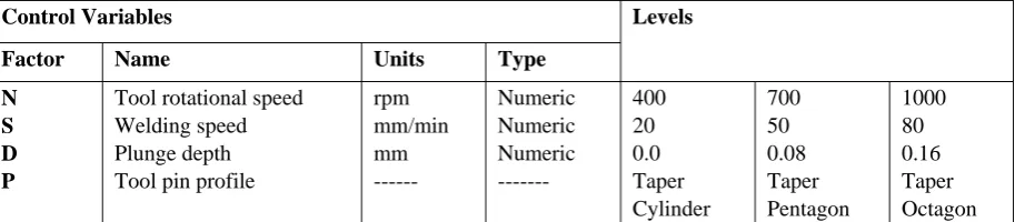
Table 2. FSW process parameters with their values at three levels
Control Variables Levels
Factor Name Units Type
N S D P
Tool rotational speed Welding speed Plunge depth Tool pin profile
rpm mm/min mm --- Numeric Numeric Numeric --- 400 20 0.0 Taper Cylinder 700 50 0.08 Taper Pentagon 1000 80 0.16 Taper Octagon Three different pin profile tools (Taper cylinder (TC), Taper Pentagon (TP), and Taper Octagon (TO) as shown in Fig. 1 were prepared with help of CNC turning centre and wire cut electric discharge machine.
Fig. 1. Tool pin profiles
The dimensions of all tools were as: pin diameter of 8 mm, pin length of 4.5 mm, taper angle 14° and shoulder diameter of 20 mm with 8° concavity at the shoulder base.
Fig. 2. Friction stir weld joint
Then the joints were subjected to tensile test for evaluation of their mechanical characterization using computerized universal testing machine (Make Enkay, EC-40T). The tensile test samples were cut from each joint with help of EDM machine. The dimensions of tensile test specimen were selected as per ASTM E-08M.
3. Results & Discussion
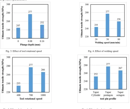
The effect of process parameters is shown in Figs. 3-6. It is clearly shown that the tensile strength is influenced by all four process parameters.
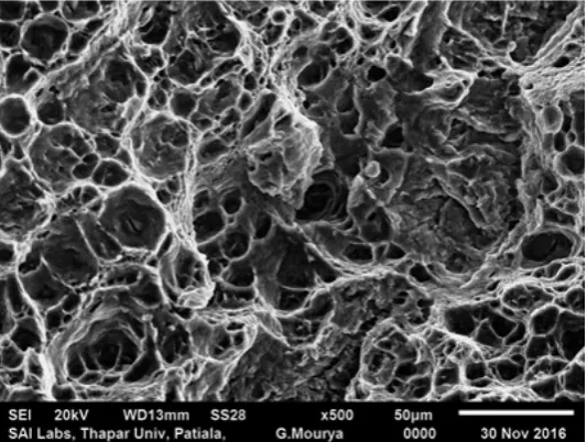
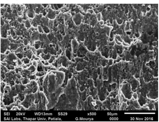
Fig. 7. Fractograph of fracture surface of tensile test specimen (Experiment no. 1)
The effects of process parameters have been discussed in following sub sections.
3.1 Effect of tool rotational speed
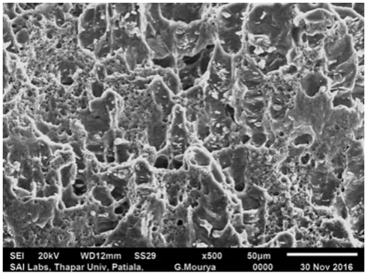
Fig. 3 Shows the effect of tool rotational speed. The tensile strength first increases then decrease with increase in tool rotational speed. The heat generation per mm length in the weld zone directly depends upon tool rotational speed. Hence at lower tool rotational speed of 400 rpm, low heat generation and less plastic deformation lowered the tensile strength. The coarse dimples in Fractograph shown in Fig. 8 are evident for the same. At tool rotational speed 700 rpm, the increased heat generation, and satisfactory material flow, led to higher tensile strength. Here the dimples are also fine and uniformly distributed Fig. 7. Tool rotational speed at 1000 rpm, higher heat generation caused grain coarsening Fig. 9, which lowered the tensile strength.
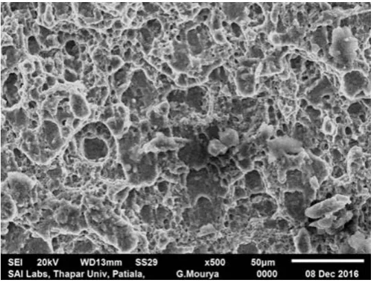
Fig. 9. Fractograph of fracture surface of tensile test specimen (Experiment no. 3)
3.2 Effect of welding speed
Fig. 4 Shows the effect of welding speed. The tensile strength first increases then decrease with increase in welding speed. Welding speed inversely affects the exposure time of frictional heat per unit length and cooling rate of weld zone, and hence affecting the grain growth. At lower welding speed of 20 mm/min, higher exposure time of frictional heat per unit length and slower cooling rate, results in coarser grain size Fig. 10, hence tensile strength is lower. Welding speed at 50 mm/min, the frictional heat per unit length may be sufficient, due to which ultimate tensile strength is higher. Fig. 7 shows fine dimples. At welding speed 80 mm/min, the reduced exposure time for heat generated per unit length and faster cooling rate reduced the degree of metallurgical changes during welding, and coarse grains Fig. 11 with lower density resulted lowest tensile strength.
Fig. 11. Fractograph of fracture surface of tensile test specimen (Experiment no. 5)
3.3 Effect of tool plunge depth
Fig. 5 shows the effect of plunge depth. The tensile strength first increases then decrease with increase in plunge depth. When no Plunge depth was applied on tool, there was no contact between tool shoulder surface and joint area, heat was generated only due to friction between pin surface and material around the pin, leading to less heat generation. The voids shown in Fig. 12 shows the lack of appropriate material bonding. Flow of material depends upon the temperature beneath the shoulder. On increasing plunge depth to 0.08 mm, there is a sufficient contact between shoulder surface with upper surface of the joint, which increases the hydrostatic pressure under the shoulder area reducing material flow stress and supporting the adequate extrusion and amalgamation of the plasticized material, resulting in higher tensile strength. Fine dimples shown in Fig. are the evidence of higher tensile strength. Any other increase in plunge depth causes excessive heat generation resulting in more material softening and grain coarsing after cooling Fig. 13.
Fig. 13. Fractograph of fracture surface of tensile test specimen (Experiment no. 7)
Also softened material comes out as flash Fig. 14 on advancing side of tool causing reduction of joint thickness, which causes in lowering tensile strength.
Fig. 14. Flash on advancing side of tool
3.4 Effect on tool pin profile
Fig. 16. Fractograph of fracture surface of tensile test specimen (Experiment no. 9)
4. Conclusions
From the above study, the following conclusions can be drawn:
1. Friction stir welding of AA5083-H321 was successfully performed with excellent joint strength. 2. Tensile strength increases with increase in values process parameters up to a certain limit and then
decrease with further increase in values of process parameters.
3. Tensile strength depends upon heat input, which is directly proportional to tool rotational speed and inversely proportional to welding speed.
4. The pulsating effect of tool pin profiles plays a major role in deciding tensile strength.
References
[1] Matrukanitz RP. (1990). ASM Handbook-Welding, Brazing and Soldering (6th ed.).
[2] Thomas, W. M. (1991). Friction stir butt welding. International Patent Application No. PCT/GB92/0220.
[3] Ericsson, M., & Sandström, R. (2003). Influence of welding speed on the fatigue of friction stir welds, and comparison with MIG and TIG. International Journal of Fatigue, 25(12), pp.1379–1387.
[4] Moreira, P. M. G. P., de Figueiredo, M. A. V., & de Castro, P. M. S. T. (2007). Fatigue behaviour of FSW and MIG weldments for two aluminium alloys. Theoretical and Applied Fracture Mechanics, 48(2), pp.169–177.
[5] Muñoz, A. C., Rückert, G., Huneau, B., Sauvage, X., & Marya, S. (2008). Comparison of TIG welded and friction stir welded Al-4.5Mg-0.26Sc alloy. Journal of Materials Processing Technology, 197(1–3), pp.337–343.
[6] Zhao, J., Jiang, F., Jian, H., Wen, K., Jiang, L., & Chen, X. (2010). Comparative investigation of tungsten inert gas and friction stir welding characteristics of Al–Mg–Sc alloy plates. Materials & Design, 31(1), pp.306–311.
[7] Lakshminarayanan, A. K., Balasubramanian, V., & Elangovan, K. (2009). Effect of welding processes on tensile properties of AA6061 aluminium alloy joints. The International Journal of Advanced Manufacturing Technology, 40(3–4), pp.286–296.
[8] Elangovan, K., Balasubramanian, V., & Valliappan, M. (2008). Influences of tool pin profile and axial force on the formation of friction stir processing zone in AA6061 aluminium alloy. The International Journal of Advanced Manufacturing Technology, 38(3–4), pp.285–295.
[9] Elangovan, K., & Balasubramanian, V. (2008). Influences of tool pin profile and welding speed on the formation of friction stir processing zone in AA2219 aluminium alloy. Journal of Materials Processing Technology, 200(1–3), pp.163–175.
[10] Padmanaban, G., & Balasubramanian, V. (2010). An experimental investigation on friction stir welding of AZ31B magnesium alloy. International Journal of Advanced Manufacturing Technology, 49(1–4), pp.111–121.
[11] Karthikeyan, P., Thiagarajan, D., & Mahadevan, K. (2014). Study of relation between welding and hardening parameters of friction stir welded Aluminium 2024 alloy. Procedia Engineering, 97, pp.505–512.
[12] Lombard, H., Hattingh, D. G., Steuwer, A., & James, M. N. (2008). Optimising FSW process parameters to minimise defects and maximise fatigue life in 5083-H321 aluminium alloy. Engineering Fracture Mechanics, 75(3–4), pp.341–354.
[13] Jayaraman, M., Sivasubramanian, R., Balasubramanian, V., & Lakshminarayanan, A. K. (2009). Optimization of process parameters for friction stir welding of cast aluminium alloy A319 by Taguchi method. Journal of Scientific & Industrial Research, 68, pp.36–43. [14] Singarapu, U., Adepu, K., & Arumalle, S. R. (2015). Influence of tool material and rotational speed on mechanical properties of
friction stir welded AZ31B magnesium alloy. Journal of Magnesium and Alloys, 3(4), pp.335–344.
[15] Panda, B., Garg, A., Jian, Z., Heidarzadeh, A., & Gao, L. (2016). Characterization of the tensile properties of friction stir welded aluminum alloy joints based on axial force, traverse speed, and rotational speed. Frontiers of Mechanical Engineering, 11(3), pp.289– 298.
[16] Cao, X., & Jahazi, M. (2009). Effect of welding speed on the quality of friction stir welded butt joints of a magnesium alloy. Materials and Design, 30(6), pp.2033–2042.
ANFIS models and simulated annealing algorithm. International Journal of Advanced Manufacturing Technology, 69(5–8), pp.1803– 1818.
[20] Tansel, I. N., Demetgul, M., Okuyucu, H., & Yapici, A. (2010). Optimizations of friction stir welding of aluminum alloy by using genetically optimized neural network. The International Journal of Advanced Manufacturing Technology, 48(1), pp.95–101.
[21] Periyasamy, P., Mohan, B., Balasubramanian, V., Rajakumar, S., & Venugopal, S. (2013). Multi-objective optimization of friction stir welding parameters using desirability approach to join Al/SiCp metal matrix composites. Transactions of Nonferrous Metals Society of China (English Edition), 23(4), pp.942–955.
[22] Liu, Y., Wang, W., Xie, J., Sun, S., Wang, L., Qian, Y., … Wei, Y. (2012). Microstructure and mechanical properties of aluminum 5083 weldments by gas tungsten arc and gas metal arc welding. Materials Science and Engineering A, 549, pp.7–13.
[23] Atabaki, M. M., Yazdian, N., & Kovacevic, R. (2016). Partial penetration laser-based welding of aluminum alloy (AA 5083-H32). Optik - International Journal for Light and Electron Optics, 127(16), pp.6782–6804.
[24] Hirata, T., Oguri, T., Hagino, H., Tanaka, T., Wook, S., Takigawa, Y., & Higashi, K. (2007). Influence of friction stir welding parameters on grain size and formability in 5083 aluminum alloy, 456, pp.344–349.