© 2017 IJSRST | Volume 3 | Issue 7 | Print ISSN: 2395-6011 | Online ISSN: 2395-602X Themed Section: Science and Technology
Predictive Torque Control Scheme for Three-Phase Four-Switch Inverter Fed
Induction Motor Drives with DC-Link Voltages Offset Suppression by Using
Fuzzy Logic Controller
Vykuntam Sandeep
1, S Sridhar
21Student, Department of Electrical and Electronics Engineering, JNTUA Anantapur, Andhra Pradesh, India
2Asst Professor, Department of Electrical and Electronics Engineering, JNTUA Anantapur, Andhra Pradesh, India
ABSTRACT
This paper proposes a three-phase four-switch (B4) inverter, having a fewer amount of switches, be primarily introduced for the possibility of reducing the inverter cost, and it proved to be extremely useful as it can be used in fault tolerant control to avoid the open/short circuit fault of the six-switch three-phase (B6) inverter. However, the balence among the phase currents collapses because of the change of the two dc-link capacitor voltages; so its application is limited. This document suggests a predictive torque control (PTC) scheme for the B4 inverter-fed induction motor (IM) with the dc-link voltage offset suppression by using fuzzy logic controller. The voltage vectors of the B4 inverter under the variation of the two dc-link capacitor voltages are determined for exact estimate and control of the torque and stator flux. The three-phase currents are forced to stay balence by directly controlling the stator flux. The voltage offset of the two dc-link capacitors is demonstrated and prohibited in the predictive point of view. A fuzzy controller is used for better control of speed and to minimize the THD in stator currents. A significant measure of simulation and experimental results are displayed to approve the proposed control scheme.
Keywords : Cost function, current unbalance, four-switch inverter, induction motor (IM) drives, model predictive control (MPC).
I.
INTRODUCTION
Throughout the years, the traditional three-phase voltage source inverter with six switches (B6) has been found across the board mechanical applications in different structures, for example, motor drives and active filters. However, in specific applications, a further cost diminishment for inverter arrangement is considered by clients. To accomplish this objective, the three-phase inverter with as it were four switches was proposed by Van der Broeck and Van Wyk [1] with the end goal of minimizing the segments' cost, and it is named four-switch three-phase (B4) inverter in examination with the B6 one, as appeared in Fig. 1. In spite of the fact that this kind of cost lessening is to the detriment of output execution, the B4 inverter can be used in fault tolerant control to solve the open/short-circuit of the B6 inverter. The possibility of the B4 inverter connected to fault tolerant control is extremely profitable in a few basic events, for example, rail traction, and it has therefore pulled in light of a legitimate concern for some specialists [2]–[4].
Figure 1. Circuit diagrams of a B4 inverter-fed induction motor drive.
The four-switch inverters are known to have a few disservices contrasted with typical six-switch inverters: the voltage use component is split contrasted with the six-switch inverter.
drives did not get numerous considerations to the specialists. Some reproduction aftereffects of PTC for the B4 inverter-fed drives copying the B6 case were completed. Be that as it may, the dc-link voltages fluctuation, which is the intrinsic feature of the B4 inverter, was not considered[13]. On account of the split switch states relating to B6 one, the constant usage time taken a toll for the PTC plot in B4 inverter is decreased in an inspecting period. This paper is sorted out as takes after. In Section II, the model of B4 inverter and induction motor (IM) is illustrated.
PARAMETERS OF THE INDUCTION MACHINE:
Rotor flux. Stator flux.
Rotor Torque Constant. Magnetizing Inductance.
Stator Leakage Inductance. Rotor Leakage Inductance. Rotor coupling element. Total Leakage Factor.
Weight factor of the dc-link capacitor. Weight factor.
Electromagnetic Torque. Rated Torque.
Stator current. Rotor current.
TABLE I. SWITCHING FUNCTION AND THE OUTPUT VOLTAGES OF THE B4 INVERTER
Stat es
Swit ch On
output Voltages
VaN VbN
Vc N
0 0 0 1
1 0
1 1 -
The proposed PTC control plot with capacitor voltage suppression is clarified in Section III. The weight figures
the fetched capacity are dissected and talked about in Section IV. In Section V, exploratory outcomes are appeared. The conclusions are introduced in Section VI.
II.
DESIGNING OF THE B4 INVERTER AND IM
A. Voltage Vector of a B4 Inverter
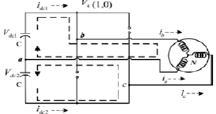
TheB4 topology comprises of a two-leg inverter, as outlined in Fig. 1. The dc-link is part into two voltage sources, to the center of which one load phase is associated. For advantageous examination, the inverter is considered for execution by perfect switches (T1–T4) (i.e., with no dead time and no immersion voltage drop).
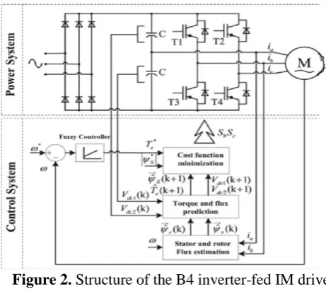
Figure 2. Structure of the B4 inverter-fed IM drive based on the PTC scheme.
III.
PROPOSED SCHEME FOR THE B4
INVERTER-FED IM DRIVE
In the proposed scheme, the internal loop is a stator flux and electromagnetic torque controller in based on PTC, while the external speed loop is a Fuzzy logic controller. The structure of the B4 inverter-sustained IM drive-based PTC scheme is appeared in Fig.2.
A. Flux Estimation
It is advantageous to note that the voltage-demonstrate based flux estimator utilizing the order voltages can around gauge the stator flux in the B6 case.[18]
in the proposed plot and the estimations of the stator flux
→ and the rotor flux
→ at the present testing step k are
required.
Utilizing Euler-based discretization as discrete conditions of the rotor and stator flux estimation are as per the following:
( )
( ) ( ) ( ) (1)
( ) ( ) ( ) (2)
Where Ts relates to the testing time, kr = Lm/Lr is the rotor coupling element and
σ = 1− (L2 m/LsLr ) is the aggregate spillage consider. As
it is clear to find in (1), the rotor flux estimation is gotten without utilizing the order voltages.
B. Electromagnetic Torque and Stator Flux Prediction
Since the control factors are stator flux is estimated above in equation (2) and electromagnetic torque is derived below as,
e( ) * ( ) ( )+ (3)
The forecast articulation of the stator current is (k + 1) is acquired utilizing the proportional condition of the stator progression of an induction machine.
The forecast condition of the stator current is at the moment k + 1 is acquired.
( ) ( ) ( )
{ ((
) ( ) v ( ))} (4)
Once the forecasts of the stator flux (2) and the stator current (4) are acquired, the forecast of the electromagnetic torque can be ascertained in (3).
C. Cost Function Optimization
The following stride in predictive control is the optimization of an fitting control law that is characterized as a cost work. The structure type of the cost function is given as takes after:
| ( ) |
|‖ ‖ ‖ ( ) ‖| ‖ ‖
i * + (5) Where i indicates the index of the stator voltage vector utilized to figure the expectations Te (k + 1) and
→ (k + 1), respectively. The component λ0 signifies a weight figure. At long last, the improvement step is completed, and the inverter voltage vector that minimizes the cost capacity is chosen as the ideal exchanging state for the following testing time frame k + 1, hence the ideal torque and flux control is accomplished.
D. Time-Delay Compensation
It is outstanding that there is one-phase delay in advanced usage. In other word, the voltage vector chose at the moment time k won't be connected until the moment time k + 1. To wipe out this deferral, the value at the moment time k + 2 ought to be utilized as a part of (18) as opposed to the moment time k + 1.
Figure 1. Current paths in the switching state V4.
E. DC-Link Voltage Offset Suppression
The improper starting phase angle of phase "a" current or the irregularity current flowing in the two capacitors will bring about voltage deviation.
Measure ent: Vdc , Vdc , 𝑖𝑘,𝜔
Apply:
𝑣𝑜𝑝𝑡
→ 𝑘
Estimate:
φ , φ
Pred ct:
𝜑𝑘+
→
𝜑𝑘+
No Yes
No
Yes
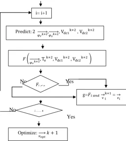
Figure 5. Implementation Flowchart Of The Proposed Scheme.
The cost work, including the voltage balance concealment, is given by adding a third term to the cost work (19)
| ( ) |
|‖ ‖ ‖ ‖ ‖( ) ‖|
| ( ) ( )|
* +
Where Vdc is dc-link voltage, which can be gotten by Vdc
= Vdc1 + Vdc2, λdc is the weight variable of the dc-link
capacitor voltage offset suppression. The minimization is finished by a comprehensive inquiry for all achievable voltage vectors. The proposed control plot can be executed in the accompanying grouping (see Fig. 5). The superscript k, k + 1, and k + 2 mean the factors' value at testing time k, k + 1, and k + 2, separately.
IV.
FUZZY LOGIC
As of recent, the number and assortment of uses of fuzzy logic have expanded essentially. The applications go from consumer products, for example, cameras, camcorders, clothes washers, and microwave stoves to
mechanical process control, restorative instrumentation, choice emotionally supportive networks, and portfolio choice. To comprehend why utilization of fuzzy logic has developed, you should first understand what is implied by fuzzy logic
Tables : Rule base for Five Membership Function Error (Voltage)
Change in Error
( )
NB NS ZE PS PB
NB PB PB PB PB PB NS PB PB PS PS PB ZE ZE ZE ZE PS PB PS NS NS NS NS PB PB PB PB NB NB PB
FUZZY MEMBERSHIP FUNCTION:
Membership functions for input1:
Membership functions for input2:
Membership function for output : i= i+1
Pred ct:
𝜑𝑟 𝑘+
→
𝜑𝑠 𝑘+
→ , Vdc , Vdc
𝐹 (
𝜑𝑟 𝑘+
→ e Vdc Vdc )
𝐹𝑖 <𝑔
i==4
g=𝐹𝑖 𝑎𝑛𝑑
v
=
𝑣𝑖
Optimize:
𝑣𝑜𝑝𝑡
V.
SIMULATION CIRCUIT:
PI CONTROLLER:
VI.
CONVENTIONAL RESULTS
(a) Speed
(b) Developed torque
(c) Stator flux
(d) Stator current behavior
Fig.6. Simulated waveforms using the conventional scheme in a B4 inverter fed IM. (a) Speed, (b) developed torque, (c) stator flux, and (d) statorcurrent behaviors during a speed-reversal maneuver at 50% rated load torque (λ0 = 3).
(a) Speed
(b) Developed torque
0.4 0.5 0.6 0.7 0.8
-600 -400 -200 0 200 400 600
Time(s)
S
pe
ed
(r
pm
)
0.4 0.5 0.6 0.7 0.8
-20 -15 -10 -5 0 5 10
Time(s)
Te
(N
m
)
0.4 0.5 0.6 0.7 0.8
-0.1 0 0.1 0.2 0.3 0.4 0.5 0.6
Time(s)
Sta
to
rflu
x(
W
b)
0.4 0.5 0.6 0.7 0.8 -20
-10 0 10 20
Time(s)
S
ta
to
r cu
rr
e
n
t
0.4 0.5 0.6 0.7 0.8
-600 -400 -200 0 200 400 600
Time
sp
ee
d(
rp
m
)
0.4 0.5 0.6 0.7 0.8
-15 -10 -5 0 5 10
Time(s)
T
or
qu
e(
N
m
(c) Stator flux
(d) Stator current behavior
Fig.7. Simulated waveforms using the conventional scheme in a B4 inverter fed IM. (a) Speed, (b) developed torque, (c) stator flux, and (d) stator current behaviors during a speed-reversal maneuver at 50% rated load torque (λ0 = 1).
(a) Capacitor voltages
(b) Speed
(c) Stator flux
(d) Developed torque behavior
Fig.8. Simulated two capacitor voltages with offset suppression method.(a) Capacitor voltages, (b) speed, (c) stator flux, and (d) developed torque behaviors during a voltage suppression method applied (λdc = 1000)
(a) Capacitor voltages
(b) speed
0.4 0.5 0.6 0.7 0.8
-0.1 0 0.1 0.2 0.3 0.4 0.5 0.6 Time(s) sta to r_ flu x( W b)
0.4 0.5 0.6 0.7 0.8 -20 -10 0 10 20 Time(s) sta to r cu rr e n t
2 4 6 8 10
-100 0 100 200 300 400 Time(s) C a p a ci to r vo lta g e s( V )
2 3 4 5 6 7 8 9
499 499.5 500 500.5 501 Time(s) sp e e d (r p m )
2 3 4 5 6 7 8 9
-0.2 0 0.2 0.4 0.6 0.8 Time(s) sta to r f lu x( W b )
2 4 6 8 10
-60 -40 -20 0 20 40 60 Time T orque (N m )
2 3 4 5 6 7 8 9
-100 0 100 200 300 400 Time(s) C a p a ci to r vo lta g e s( V )
2 3 4 5 6 7 8 9
(c) stator flux
(d) developed torque behaviour
Fig.9. Simulated two capacitor voltages with offset suppression method.(a) Capacitor voltages, (b) speed, (c) stator flux, and (d) developed torque behaviors during a voltage suppression method applied (λdc = 2000).
FUZZY LOGIC CONTROLLER:
PROPOSED RESULTS:
(a) Speed
(b) Developed torque
(c) Stator flux
(d) Stator current
Fig.9 Simulated waveforms using the proposed scheme in a B4 inverter fed IM behaviors during a speed-reversal maneuver at 50% rated load torque (λ0 = 3).
(a) Speed
2 3 4 5 6 7 8 9
0 0.1 0.2 0.3 0.4 0.5 0.6 0.7
Time(s)
sta
to
r f
lu
x(
N
m
)
2 4 6 8 10
-10 0 10 20 30 40
Time
T
orque
(N
m
)
0.4 0.5 0.6 0.7 0.8
-600 -400 -200 0 200 400 600
Time(s)
S
pe
ed
(r
pm
)
0.4 0.5 0.6 0.7 0.8
-20 -15 -10 -5 0 5 10
Time(s)
Te
(N
m
)
0.4 0.5 0.6 0.7 0.8
-0.1 0 0.1 0.2 0.3 0.4 0.5 0.6
Time(s)
S
ta
to
r f
lu
x(
W
b
)
0.4 0.5 0.6 0.7 0.8
-20 -10 0 10 20
Time(s)
S
ta
to
r cu
rr
e
n
t(
A
)
0.4 0.5 0.6 0.7 0.8
-600 -400 -200 0 200 400 600
Time(s)
S
pe
ed
(r
pm
(b) Developed torque
(c) Stator flux
(d) Stator current
Fig.10. Simulated waveforms using the proposed scheme in a B4 inverter fed behaviors during a speed-reversal maneuver at 50% rated load torque (λ0 = 1).
IM .
(a) Capacitor voltages
(b) Speed
(a) Stator flux
(a) Developed torque
Fig.11. simulated two capacitor voltages with offset suppression method. Behaviors during a voltage suppression method applied (λdc = 1000).
(a) Capacitor voltages
0.4 0.5 0.6 0.7 0.8
-15 -10 -5 0 5 10 Time(s) T e (N m )
0.4 0.5 0.6 0.7 0.8
-0.2 0 0.2 0.4 0.6 0.8 Time(s) S ta to r f lu x( W b )
0.4 0.5 0.6 0.7 0.8
-20 -10 0 10 20 Time(s) S ta to r cu rr en t(A )
2 4 6 8 10
-100 0 100 200 300 400 Time(s) C a p a ci to r V o lta g e s( V )
2 4 6 8 10
499 499.5 500 500.5 501 Time(s) S p e e d (r p m )
2 4 6 8 10
-0.2 0 0.2 0.4 0.6 0.8 Time(s) S ta to r f lu x( W b )
2 4 6 8 10
-30 -20 -10 0 10 20 30 40 Time T orque (N m )
2 4 6 8 10
(a) speed
(c) Stator flux
(d) Developed torque
Fig.12. Simulated two capacitor voltages with offset suppression method behaviors during a voltage suppression method applied (λdc = 2000). Results comparison table:
S.No. Variable Name
Proposed THD (%)
Extension THD (%) 1. Stator
current when λ0 = 3
0.83 0.19
2. Stator current when λ0 = 1
7.19% 4.68%
3. Stator current
0.65 0.06
when = 1000
4. Stator current when = 2000
0.66 0.08
VII.
CONCLUSION
In this paper, the uncommon issues on utilizing the acclaimed PTC control conspire for a B4 inverter-fed IM drives are investigated also, talked about. The voltage vectors of the B4 inverter under the conversion of the two dc-link capacitor voltages are inferred for exact expectation and control of the torque and stator flux. The proposed B4 inverter-fed IM drive has been discovered satisfactory for best modern variable-speed-drive applications considering its cost diminishment and other characteristic profitable components. Unquestionably, the extra work is still stayed to grow more productive PTC plan and answers the rest of the inquiries: the power toward parameter deviation, parameter affectability of this plan, for the parameter qualities may differ in the motor drives, while in different cases it is hard to get an exact value of the parameters.
VIII.
REFERENCES
[1]. H. W. Van der Broeck and J. D. Van Wyk, "A comparative investigation of a three-phase induction machine drive with a component minimized voltage-fed inverter under different control options," IEEE Trans. Ind.Appl., vol. IA-20, no. 2, pp. 309–3IA-20, Mar. 1984.
[2]. B. A. Welchko, T. A. Lipo, T. M. Jahns, and S. E. Schulz, "Fault tolerant three-phase AC motor drive topologies: A comparison of features, cost, and limitations," IEEE Trans. Power Electron., vol. 19, no. 4, pp. 1108– 1116, Jul. 2004.
[3]. R. L. D. Ribeiro, C. B. Jacobina, E. R. C. da Silva, and A. M. N. Lima,"Fault-tolerant voltage-fed PWMinverter AC motor drive systems," IEEE Trans. Ind. Electron., vol. 51, no. 2, pp. 439–446, Apr. 2004.
[4]. D. Campos-Delgado, D. Espinoza-Trejo, and E. Palacios, "Fault-tolerant control in variable speed drives: A survey," Electric Power Appl., IET, vol. 2, no. 2, pp. 121–134, 2008.
2 4 6 8 10
-100 0 100 200 300 400 500 600
Time(s)
S
p
e
e
d
2 4 6 8 10
0 0.1 0.2 0.3 0.4 0.5 0.6 0.7
Time(s)
S
ta
to
r f
lu
x(
W
b
)
2 4 6 8 10
0 5 10 15 20 25 30
Time
T
orque
(N
m
[5]. F. Jen-Ren and T. A. Lipo, "A strategy to isolate the switching device fault of a current regulated motor drive," in Proc. IEEE Ind. Appl. Soc. Annu. Meeting, Conf. Rec., 1993, vol. 2, pp. 1015–1020. [6]. D. Sun, Z. Y. He, Y. K. He, and Y. F. Guan,
"Four-switch inverter fed PMSM DTC with SVM approach for fault tolerant operation," in Proc.IEEE Int. Electric Machines Drives Conf., 2007, vol. 1– 2, pp. 295–299.
[7]. L. Tian-Hua, F. Jen-Ren, and T. A. Lipo, "A strategy for improving reliability of field-oriented controlled induction motor drives," IEEE Trans.Ind. Appl., vol. 29, no. 5, pp. 910–918, Sep./Oct. 1993.
[8]. M. B. D. Correa, C. B. Jacobina, E. R. C. da Silva, and A.M. N. Lima, "Ageneral PWMstrategy for four-switch three-phase inverters," IEEE Trans. Power Electron., vol. 21, no. 6, pp. 1618–1627, Nov. 2006.
[9]. F. Blaabjerg, D. O. Neacsu, and J. K. Pedersen, "Adaptive SVM to compensateDC-Link voltage ripple for four-switch three-phase voltage-source inverters," IEEE Trans. Power Electron., vol. 14, no. 4, pp. 743–752,Jul. 1999.
[10].J. Kim, J. Hong, and K. Nam, "A current distortion compensation schemefor four-switch inverters," IEEE Trans. Power Electron., vol. 24, no. 3–4,pp. 1032–1040, Mar.–Apr. 2009.
[11].D. M. Lee, J. B. Park, and H. A. Toliyat, "A simple current ripple reduction method for B4 inverters," J. Elect. Eng. Technol., vol. 8, no. 5, pp. 1062– 1069, Sep. 2013.
[12].R. Wang, J. Zhao, and Y. Liu, "A comprehensive investigation of four switch three-phase voltage source inverter based on double Fourier integral analysis," IEEE Trans. Power Electron., vol. 26, no. 10, pp. 2774–2787,Oct. 2011.
[13].M. N. Uddin, T. S. Radwan, and M. A. Rahman, "Fuzzy-logic controller-based cost-effective four-switch three-phase inverter-fed IPM synchronous motor drive system," IEEE Trans. Ind. Appl., vol. 42, no. 1, pp. 21–30, Jan.–Feb. 2006.
[14].S. A. R. Kashif, M. A. Saqib, and S. Zia, "Implementing the induction motor drive with four-switch inverter: An application of neural networks,"Expert Syst. Appl., vol. 38, no. 9, pp. 11137–11148, Sep. 2011.
[15].B. El Badsi, B. Bouzidi, and A.Masmoudi, "DTCscheme for a four-switch inverter-fed induction motor emulating the six-switch inverter operation,"IEEE Trans. Power Electron., vol. 28, no. 7, pp. 3528–3538, Jul. 2013.
[16].J. H. Lee, "Model predictive control: Review of the three decades of development," Int J Control Autom., vol. 9, no. 3, pp. 415–424, Jun. 2011. [17].J. Holtz and S. Stadtfeldt, "A predictive controller
for the stator current vector of ac machines fed from a switched voltage source," in Proc. IEEE IPEC, 1983, vol. 2, pp. 1665–1675.
[18].R. Kennel and D. Sch¨oder, "A predictive control strategy for converters," in Proc. IFAC Control Power Electron. Elect. Drives, 1983, pp. 415–422. [19]. J. Rodriguez, R. M. Kennel, J. R. Espinoza, M.