www.orientjchem.org
An International Open Free Access, Peer Reviewed Research Journal
2018, Vol. 34, No.(4): Pg. 1884-1889
This is an Open Access article licensed under a Creative Commons Attribution-Non Commercial-Share Alike 4.0 International License (https://creativecommons.org/licenses/by-nc-sa/4.0/), which permits unrestricted Non Commercial use, distribution and reproduction in any medium, provided the original work is properly cited.
Effect of different Current density on Properties of Electrodeposited
Ni-Co-Cr Thin Films
S. P. MEENA
1* and R. ASHOk kUMAR
21Research and Development Centre, Bharathiar University, Coimbatore-641 046, TamilNadu, India.
2PG and Research Department of Physics, Thiruvalluvar Government. Arts College, Rasipuram-637 401,
TamilNadu, India.
*Corresponding author E-mail: [email protected]
http://dx.doi.org/10.13005/ojc/3404023
(Received: June 18, 2018; Accepted: July 27, 2018)
ABSTRACT
Ni-Co-Cr thin films were electroplated for different current density. FCC structured crystals were observed in XRD study and soft magnetic properties of NiCoCr thin films for different current density were compared. Electroplated Ni-Co-Cr films were prepared with different current density (2, 3, 4 and 5 mA/cm2) and they were subjected to magnetic, structural, morphological and mechanical
characterization analysis. Cobalt composition was minimum as 21.31 wt% for current density 5 mA/ cm2. The chromium content increased when current density was increased. Ni-Co-Cr films were
evenly coated on copper surface. Thin films deposits with high current density shows high saturation magnetization and low coercivity.The microhardness of deposits increases when current density is increased.
keywords: Crystals size, Electrodeposition, Electrolytic bath, SEM, X-ray diffraction, VSM, VHN, Face Centered Cubic (FCC).
INTRODUCTION
There is a rising interest in Ni-Co thin films with chromium for innovative applications1. Ni-Co
thin films reveal magnetic, detecting and catalytic properties as an element of nickel and cobalt metals formed into spinel type structures. Ni-Co is a spinel compound which can give sufficient transmissivity from visible wavelength2-5. Ni–Co alloy are important
magnetic alloy materials which are largely and
commercially used in industry due to its excessive saturation magnetization, high coercive force, excessive electric permeability and minimum eddy current loss. This Ni-Co alloy are utilized in specific applications for example organic and inorganic alloy electrosynthesis, super capacitors, electro catalyst for anodic oxygen reaction, IR translucent electrodes for panel displays, switches, sensors and optical limiters6-10. It was proven that Ni-Co-Cr
1885
MEENA
et al.,Orient. J. Chem., Vol. 34(4), 1884-1889(2018)due to its soft magnetic character and its great mechanical properties, have revealed an incredible potential in MEMS, NEMS, recording devices, optical and sensors industries11-14. In this investigation,
the magnetic, structural, elemental composition and mechanical characterization of electro plated Ni-Co-Cr films have been studied with different current density.
EXPERIMENTAL
The Ni-Co-Cr composite films were electroplated on copper substrate for different current density 2, 3, 4 and 5 mA/cm2. The processing time
of deposition was 15 minutes. In this experiment, Cu and stainless steel substrates acted as cathode and anode respectively with 1.5 cm x 7.5 cm. dimension15-19. The Ni-Co-Cr composite films were
synthesized from electrolytic solution which contain Cr2 (So4)3 (10 g/l), (NH4)2SO4 (40 g/l), CoSo4(15 g/l), C6H8O7 (10 g/l) and NiSo4 (30 g/l).The pH value is
maintained as 6.0 in electrolytic solution by adding NH3 and electro chemical process was processed
with different current density 2,3,4 and 5 mA/cm2.
The cathode plate was taken out from the solution after 15 min. and dried for couple of minutes. Analysis with scanning electron microscope and X-ray diffractometer provide surface and structural characters of thin films. Vickers hardness test provide micro hardness of films. The vibrating sample magnetometer provides magnetic properties of Ni-Co-Cr thin films20-21.
RESULTS AND DISCUSSION
Composition of electrodeposited thin films
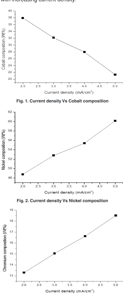
From result, the cobalt compositions decrease as 37.91%, 32.15%, 27.95% and 21.31% for current density 2, 3, 4 and 5 mA/cm2 respectively.
Nickel compositions increase as 48.79%, 52.80%, 55.42% and 60.16% for current density 2, 3, 4 and 5 mA/cm2 respectively. Chromium compositions
are as 13.30%, 15.05%, 16.63% and 18.52% for current density 2, 3, 4 and 5 mA/cm2 respectively.
EDS result indicates that the films received with high current density have high nickel content. The high cobalt content of 37.91wt% was received for low current density. EDS result shows that nickel
content increases with increasing current density. The weight percentage of chromium increases while increasing current density. Fig. 1, 2 and 3 show the variation of cobalt, nickel and chromium composition with increasing current density.
Fig. 1. Current density Vs Cobalt composition
Fig. 2. Current density Vs Nickel composition
Fig. 3. Current density Vs Chromium composition
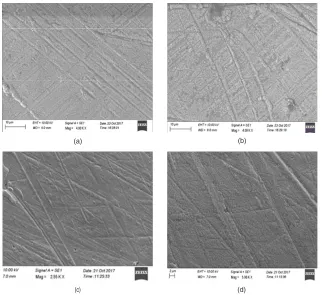
Morphological observation
SEM pictures are shown in Fig. 4.The electroplated thin films appears without cracks and uniform. They
are bright in nature. It concludes that the deposition of materials on the substrate is uniform.
(a) (b)
(c) (d)
Fig. 4. SEM images for electrodeposited Ni-Co-Cr thin film for different current density (a) 2 mA/cm2 (b) 3 mA/cm2 (c) 4 mA/cm2 (d) 5 mA/cm2
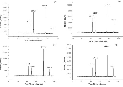
Structural analysis
The crystal structure of Ni-Co-Cr alloy thin films was found by XRD analysis. Fig. 5 demonstrates crystal patterns of the Ni-Co-Cr alloys which electrodeposited from electrolytic bath. The XRD studies indicates that electrodeposited magnetic alloys have different crystal orientations. XRD peaks of the alloys shows a preferred orientation along the (111), (200), (220), and (311) planes.
From XRD data’s, grain size values of the alloys on substrate were calculated using the full width at half maximum intensity(β), wavelength(λ) and Bragg’s angle(θ)
D=0.954λ/β cosθ
The average crystallite size is around 17 nm. The particle size decreases as 20.38, 18.13, 15.93 and 13.10 for current density 2, 3, 4 and 5
mA/cm2 respectively. Dislocation density and strain
of Ni-Co-Cr alloy increase when current density increases. XRD data’s are shown in Table 1.When the current density is 5 mA/cm2, the crystalline size
of thin film is 13.10 nm.
Mechanical properties
Micro hardness investigation of deposits has been done by Vickers hardness tester. The hardness values of thin films prepared with increasing current density are 54, 69, 76 and 95 VHN respectively. So it is confirmed that the hardness increases with increasing current density due to lower strain associated with thin films. Fig 7 indicates the variation of hardness with increasing current density.
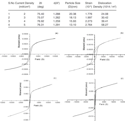
Magnetic properties of the deposits
1887
MEENA
et al.,Orient. J. Chem., Vol. 34(4), 1884-1889(2018)shown in Fig. 8. It is noted that magnetization value increases as 0.619 x 10⁻³ emu/cm2, 1.692 x 10⁻³ emu/
cm2, 4.919 x 10⁻³ emu/cm2 and 10.04 x 10⁻³ emu/cm2
for current density 2,3,4 and 5 mA/cm2 respectively
The film coated with high current density exhibits the low coercivity and high magnetization. The coercivity value decreases as 478G, 375G, 263G and 178 G for
current density 2,3,4 and 5 mA/cm2 respectively. The
retentivity values are 0.177 x 10⁻³ emu/cm2, 0.570
x 10-3 emu/cm2, 0.8174 x 10⁻³ emu/cm2 and 4.690 x
10-3 emu/cm2 for current density 2, 3, 4 and 5 mA/cm2
respectively. Squareness values are 0.2859, 0.3368, 0.1661 and 0.4668 for current density 2, 3, 4 and 5 mA/cm2 respectively.
Fig. 5. XRD Patterns of Ni-Co-Cr thin films for different current density (a) 2 mA/cm2 (b) 3 mA/cm2 (c) 4 mA/cm2 (d) 5 mA/cm2
Fig. 6. Crystals size as a function of current density Fig. 7. Vickers Hardness as a function of current density
It was observed that the magnetization and retentivity increase by increasing current density. From VSM result, it is concluded that films prepared
Table 1: Structural characteristics of Ni-Co-Cr alloy thin films
S.No Current Density 2θ d(A0) Particle Size Strain Dislocation
(mA/cm2) (deg) (D)(nm) (10-3) Density (1014 / m2)
1 2 75.40 1.288 20.38 1.776 24.08
2 3 75.07 1.262 18.13 1.997 30.42
3 4 76.92 1.259 15.93 2.273 39.41
4 5 76.31 1.291 13.10 2.764 58.27
Fig. 8. Magnetic hysteresis loops for Ni-Co-Cr thin film for different current density (a) 2 mA/cm2 (b) 3 mA/cm2 (c) 4 mA/cm2 (d) 5 mA/cm2
CONCLUSION
The surface, elemental composition mechanical and magnetic characters of Co-Ni-Cr thin films have been investigated by varying current density (2, 3, 4 and 5 mA/cm2) at 30°C for
15 minutes. The thin films received with various current density are evenly coated and shiny. FCC structure was crystal formation of Ni-Co-Cr composite films. Microhardness increases with increasing current density. When current density was increased from 2 to 5 mA/cm2, the crystallite
size values decreases from 20.38 nm to 13.10 nm. The crystallite size are reduced with increasing
current density. This happens due to nano crystalline structure and low film strain associated with Ni-Co-Cr alloy thin films.When current density was increased from 2 to 5 mA/cm2, the magnetization
values increases from 0.619 x 10⁻³ emu/cm2 to
10.04 x 10⁻³ emu/cm2. This happen due to nano
structured crystal deposition. So it is concluded that soft magnetic nature of thin films is enhanced by increasing current density.
ACkNOWLEDGEMENT
1889
MEENA
et al.,Orient. J. Chem., Vol. 34(4), 1884-1889(2018)Dr.T. Baskar, Professor, Department of Physics, Vidyaa Vikas College of Engineering and Technology,
Tiruchengode, Tamilnadu, India for providing technical support.
REFERENCES
1. Gibbs, M.R.J.; Hill, E.W.; Wright, P. J.
J. Phys. D: Appl. Phys., 2004, 37, 237-244.
2. Myung, N.V.; Park, D.Y.; Yoo, B.Y. ; Sumodjo, P. T. A. J. Magn. Magn. Mater., 2003, 265, 189-198.
3. Yang Xiao-kui,; LI Qing,; Zhang Shi-yan,; GaoHui,; LuoFei,; Dai Yan. Journal of
Solid State Electrochemistry., 2010, 14(9),
1601−1608.
4. JiangHui,; LI Yun-dong,; Huang Wei-hua,; TianHui. Applied Surface Science., 2008,
254(21), 6865−6869.
5. Emerson, R.N.; Kennady, C.J.;.Ganesan, S.
Thin solid films., 2007, 515, 3391-3396.
6. Tury, B.; Radnóczi, G.Z.; Radnóczi, G.; Varsányi, M .L. J. Surface and Coatings
Technology., 2007, 202(2), 331−335.
7. Shi, L.; Sun, C. F.; Zhou, F.;Liu, W. M. Material
Science and Engineering A., 2005, 397(1−2),
190−194.
8. Lupi, C.; Dell'era, A.; Pasquali, M.; Imperatori,
P. J. Surface and Coatings Technology., 2011,
205(23−24), 5394−5399.
9. Shi Lei; Sun Chu-feng; Gao Ping; Zhou Feng; Liu Wei-min. J Applied Surface Science.,
2006, 252(10), 3591−3599.
10. Chen, W.; Xia, C.; Alshareef, H.N. ACS nano.,
2014, 9, 9531-9541.
11. Watson, S. W.; Walters, R. P. Journal of
Electrochemical Society., 1991, 138(12),
3633−3637.
12. Tury, B.; Lakatos, M.;Roya, S. Surface &
Coatings Technology., 2006, 6, 6713-6717.
13. Burzyn´ska, L.; Rudnik, E. J. Hydrometallurgy
2000, 54(2−3), 133−149.
14. Tian Liang-liang; Xu Jin-cheng; Qiang Cheng-wen. J. Applied Surface Science., 2011,
257(10), 4689−4694.
15. Fenineche, N. E.; Coddet, C.; Saida, A.
J. Surface and Coating Technology., 1990,
41(1), 75−81.
16. Meena, S. P.; Ashokkumar, R. Rasayan
J.Che., 2018, 11, 766-772.
17. QiaoGui-ying; Jing Tian-fu; Wang Nan; Gao Yu-wei; Zhao Xin; Zhou Ji-feng; Wang Wei.
J. Electrochemica Acta., 2005, 51(1),
85−92.
18. Shi, Z.; Deng, K.; Li, L. Sci Rep., 2015, 5, 9317. 19. Ghaferi, Z.; Sharafi, S.; Bahrololoom, M.E.
Appl. Surf. Sci., 2015, 355, 766-773.
20. Correia,A. N.; Machado,S.A.S. Electrochemica Acta., 2000, 45, 1733-1740.
21. Ghaferi, Z.; Sharafi, S.; Bahrololoom, M.E.