Maximum Power Point Tracking Based Power
Distribution Frequency Control In A Hybrid Power
Grid
Taliya Yazdani, Shamsher Ansari
Abstract— A large penetration of renewable electric generation sources causes an imbalance between supply and demand in power systems because their output is highly dependent on unpredictably varying parameters like weather and temperature. Although the power unbalances in the system caused by load disturbance or frequency fluctuation, can be partially recovered by inertia energy, maintaining the frequency deviation within the acceptable operating band is still a very tough problem. An LFC model of a hybrid smart microgrid with different renewable and non-renewable generations along with their constraints is presented. Also, a control Scheme for frequency disturbances using MPPT is proposed for a microgrid with Battery system, where both renewable and Non-renewable generation is harmonized to achieve a desired operational performance of the microgrid. A standard test model with a standalone microgrid with DG, BESs, wind farm and solar cells is simulated in Simulink to analyze the efficacy of the model. The Simulation shows that with MPPT and BESs, the load frequency and energy constraints can be regulated according to the power constraints on the grid. This enhances the system stability in the complex operation region even when the grid is using renewable resources and intermittent load disturbances. Index Terms— DG (Diesel Generation), Battery Energy System (BES), MPPT (Max power point tracking), Hybrid grid, load frequency control (LFC).
—————————— ——————————
1 I
NTRODUCTION An Energy distribution System with the capabilities of multimodal transfer of energy between all parties of the energy cycle and the integration of both renewable and non-renewable energy infrastructures in the power generation is termed as Smart Energy System. Currently, no universally agreed definition of smart Energy exists. However, in this paper, we have defined smart energy as, A secure, sustainable, and cost-effective energy transmission system in which production and distribution of renewable energy are integrated and coordinated in the system by active users, interactive services and enabling technologies while reducing the generation and transmission losses and losses due to fluctuations. A micro-grid having a high percentage of renewable energy will rely extensively on automation and artificial intelligence, including various sensors and actuators, an assortment of process control technologies; service-based designs, and improved user-centric business models rather than just fixed priced energy trading. These solutions are required to operate the complex control and optimized integrated micro-grid system.Rifkin considers five basic components of this revolution, which are
A Switch to Sustainable energy;
Building reserve of sustainable micro power plants for an
on-site gathering of renewable energies;
Focus on the storage of intermittent energy in every
building infrastructure;
Multimodal system of power grid which allows for two
way energy transfers between various stakeholders and users where users can connect and make contacts;
Converting the car fleets to electric plug-in and fuel cell
automobiles to act as small mobile interactive power grids that can trade energy.
In modern time, Solar and wind power generations are widely used sustainable energy generations. However, these renewable energy generators cannot ensure constant electric output which causes an imbalance between supply and demand which in turn makes the steady and reliable operation of infrastructure more difficult (Kumar, N.K. and Naidu, I.E.S., 2014 [9]). Due to the above-mentioned problem, Battery System is needed for the onboard energy storage which can supplement the energy spike and trusses due to any fluctuation in power generation or energy demand (WondwosenEshetu, Pawan Sharma and Charu Sharma, 2018 [10]).
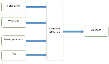
Fig 1 Hybrid microgrid model
————————————————
Taliya Yazdani is currently pursuing masters degree program in Electrical and Electronics Engineering from AKGEC, Ghaziabad. She received her graduate degree from AIET, Lucknow in Electrical Engineering, 2017
1644 Micro-grids that include renewable energy generation sources
are used in remote areas of the globe. However, the micro-grid frequency may be affected due to fluctuations caused by the intermittence energy sources (Rashidi, M. et al., 2004 [3]). Therefore, to restrain the frequency deviation many different frequency control methods are examined. The optimizations with the MPPT control are applied to the microgrid system to regulate the output power fluctuation(Tomy, F.T. and Prakash, R., 2014 [4]). Battery energy systems (BES) are also employed for controlling the power fluctuation of the grid but high device cost and hazard implications make it difficult to use. The proposed LFC is employed for regulating frequency deviation in an uncertain power system.
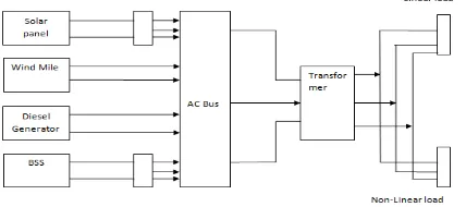
Fig 2 Proposed System Model in Simulink
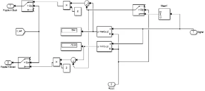
Fig 3 Proposed System Model in MPPT mode
Closer integration and coordination of different energy infrastructures are a precondition for a cost-effective microgrid system with a high percentage of non-conventional energy. The impending energy crisis has provided new opportunities for the power industry to meet ever-increasing demand. Opportunities such as designing of an energy network that is open, collaborative and distributive, allowing anyone to use it anywhere and anytime. The goal of these power grids is to build an intelligent collaborative infrastructure bridging the gap between neighbourhoods, cities, countries and the global economy, in a global network allowing for not only on-site generation of power but also closer trade of energy between various regions.
2
P
ROPOSEDM
ETHODThe introduction of Large-scale renewable energy in a microgrid implies that the basis of successful integration of renewable generation is to focus on the entire power system. Successful integration of fluctuating renewable energy, calls
for the reevaluation of complex interactions of energy production methods, storage, distribution, and consumption. Successful integration of renewable generation sources in the microgrid calls for a radically different shift in the current thinking that is distinct from the current centralized systems of the power to a single integrated autonomous energy system.
In Power Grid operation, the frequency of the system must be maintained in between a tight tolerance band for the efficient and smooth running of the system (Mariano, S.J.P.S. et al., 2009 [2]). There are a few reasons for the strict limitations on frequency deviations. The Running speeds and frequency of the three-phase a.c. motors are directly proportional to each other. Therefore, motor performance will be directly affected by any variation in system frequency. The blades of the steam turbines used in power generation are rated for a particular speed for optimal operation and any change in frequency will directly affect the speed (Pahasa, J. and Ngamroo, I, 2014[6]). Change in the frequency may cause excessive vibration and cause damages in the power generation system. The frequency error can also cause havoc in the energy storage and distribution process. Also, the imbalance between the generation and load frequencies will cause the system to be less stable and efficient(Sadeh, J. and Rakhshani, E, 2008 [5]).
In this paper, we designed and analyzed a hybrid microgrid with a mix of conventional and state of the art modern system like photovoltaic and WTG system for the optimal transfer of power between generation systems and load pressures on the grid. We designed a double LFC controller-based architecture for isolated microgrids to reduce power perturbation and load fluctuation (T. L. Vandoorn et. al, 2012 [7]). PV system in an in a hybrid microgrid is restricted in the max power operation mode. BES is operated in either constant charging or constant discharging cycle. The double SM controller is used in Wind turbine generator to restrict the frequency perturbations and prevent power fluctuation. Modelling of Various Power generation systems (Wang, C. et. al, 2016 [8])
Photovoltaic operated in MPPT mode
Battery system operated in a constant
charging-discharging cycle
Wind Power Generation Turbine with Pitch angle
Controller
Diesel Generator with Load Frequency Controller
2.1 Photovoltaic Power Generation System
In Fig 4 the block simulates a photovoltaic (V. Ravikumar and A. Feliachi, 2015 [12]) as a parallel-connected current source, 2 exponential diodes, a parallel-connected resistor Rp and series-connected resistance Rs. The o/p current given by-equation-1 [4]
I = Iph - Is*(e^((V+I*Rs)/(N*Vt))-1) -
Is2*(e^((V+I*Rs)/(N2*Vt))-1) - (V+I*Rs)/Rp eqn 1
Fig. 4 Solar energy Generation Subsystem
Fig.4 shows the subparts of a photovoltaic power generation system simulated in simulink. The standard photovoltaic system consists of two primary components Solar microgrid systems - Solar cells are prime parts of photovoltaic boards. Most are produced using silicon. Grid interactive battery bank - To achieve more reliability and provide good energy quality, a standalone system must have a storage system or must be oversized. In the case of batteries, a charge controller should be included to prevent surpassing limits that may damage them.
The efficiency of a PV cell is directly proportional to the amount of sunlight and the load characteristics. With varying sunlight, the load characteristic for the most efficiency of energy transmission changes, so for the optimum system efficiency, the load characteristic must be regulated. This load characteristic which gives the highest efficiency is termed max powerpoint and the process of locating this point and keeping the load in that range is called MPPT. The relationship between temperature and resistance of a PV cell is highly complex which results in a non-linear I-V curve and o/p efficiency. The purpose of this system is to sample the o/p and regulate the load for max power transmission in any condition.
Fig 5 Buck-Boost Sub System
In Fig 5 the block simulates a buck-boost subsystem of a solar energy generation subsystem which is used for power transfer between DGs at a different level. To keep the running of the system in the MPPT mode we have simulated the controller using MATLAB. This controller controls the system voltage, so as to keep it operating at peak voltage and max power point on power voltage curve.
% function code for PV operation in MPPT mode function d = MPPT(Vn,Vo,Pn,Po,d1)
%V=Input Voltage; v1=New Voltage; I=Input current; a=New current;d=Calculated duty cycle
%d1 = 0.33; dV=Vn-Vo; %dI=Inew-Iold;
%Pnew=Vnew*Inew; %Pold=Vold*Iold;qa dP=Pn-Po;
dX=dP*dV; if (dX==0) d = d1; else
if (dX>0)%(dP> 0)&&(dV>0) d=d1-0.3;
% else if (dP> 0)&&(dV<0) % d=d1+0.001;
% else if (dP< 0)&&(dV<0) % d=d1-0.001;
else d=d1+0.3; % end
% end end
end
Fig. 6 IGBT circuit
In Fig 6 the block simulates an IGBT circuit of energy generation subsystem which is used for high power switching.
2.2 Wind Powered Turbine with pitch Angle Controller The block in Fig 7 Implements a Wind Turbine Generator (R. Sebastian and J.Quesada, 2006 [11] with a Pitch angle Controller that model most Common turbine blades and a double SM based Controller to reduce ACE.
Fig 7 Wind Turbine Model
1646
TABLE 1 – SYSTEM SPECIFICATION OF WTG Element-wise gain (y = K.*u)
Gain 500
Nominal mechanical o/p power 8.5e3 W
The base power of the generator 8.5e3/0.9
VA
Base wind speed 12 m/s
Pitch angle beta to display wind-turbine power characteristics (beta >=0)
0deg
The generator speed is the first I/p. The generator's base speed is the same as its synchronous speed for both synchronous and asynchronous generator. The generator speed produced at the nominal voltage at zero loadings is called the base speed. The blade pitch angle (beta) in degrees is the second i/p. The wind speed (m/s) is the third input. The torque operating on the shaft is the output of the system.
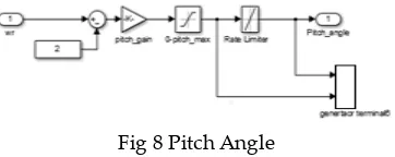
Fig 8 Pitch Angle
This block in Fig 8 depicts the pitch controller of a wind turbine model. Its characteristics at any specific pitch angle can be plotted by selecting wind turbine power characteristics.
2.3 Diesel Generator with load Frequency Controller
Diesel Generator (a unit of diesel engine and governor) is a device which produces electrical energy by converting fuel into electrical energy with the help of a governor. A governor is an electromechanical device for automatically controlling the engine speed about fuel intake.
Fig. 9 Diesel Generator with LFC
The block diagram in Fig 9 depicts the simulation of a three-phase synchronous generator. The stator is coupled to the neutral point of the generator. The back EMF in a three-phase generator can be sinusoidal or trapezoidal. For the sinusoidal machine, the back EMF can be around or salient pole. For the trapezoidal machine, it will be round. For the Sinusoidal back EMF, Preset models are available. DG set is an electro-mechanical device which converts fuel into electrical energy. A governor is a device to control engine speed about the intake of fuel. The controller is used to keep the turbine operating at its designed speed.
TABLE 2 – INITIAL CONDITIONS OF DG
Dw 0%
Th -68.7412deg
Ia 1020.62A
Ib 1020.62A
Ic 1020.62A
Pha 7.51406e-14deg
Phb -120 deg
Phc 120 deg
Vf 10.4482 V
TABLE 3 – SYSTEM SPECIFICATION OF DG
Nominal power 2e+006VA
Voltage 400V
Frequency 50Hz
Field current 100A
Stator Rs 0.00076ohm
Stator Ll 1.273e-005H
Stator Lmd 0.0005246H
Stator Lmq 0.0003845H
Field Rf' 0.0001576ohm
Field Llfd' 8.703e-005H
Dampers- Rkd' 0.0161ohm
Dampers- Llkd' 0.0005447H
Dampers- Rkq1' 0.002145ohm
Dampers- Llkq1' 5.204e-005H
Inertia J 56.29*2+.2252
kg.m2
friction factor F 0.8*2 N.m.s
pole pairs p 2
2.4 Battery Energy Storage System
Charge mode: the battery is charged from the grid and available sustainable power to a threshold limit which avoids system degradation;
Discharge modes: the battery releases energy in the system when needed. The energy required should be lower than the discharging rate of BES to protect the system.
Fig 10 Battery Model
The block in Fig 10 depicts the simulation of a generic battery. At the Rated Capacity (Ah) the Nominal Voltage (V) in Initial State-Of-Charge is 67.
3 R
ESULTS ANDA
NALYSISPerturbations in the power systems loading affects primarily the system frequency and the real power of the system. The proposed controller mainly deals with the control of the system frequency and real power. If we implement the hybrid system alone will result in the load fluctuation. We have incorporated a hybrid system with a Diesel generator and a BES.
Table 4 – Simulation parameters for the photovoltaic based microgrid
SIMULATION PARAMETERS
K 4
Turbine time constant, 0.05 Governor time constant, 0.025
electrical generator (VA): 8.5e3/0.9 Engine time delay Td (s) -0.024
Nominal power 2e+006
Voltage 400
Frequency 50
Field current 100
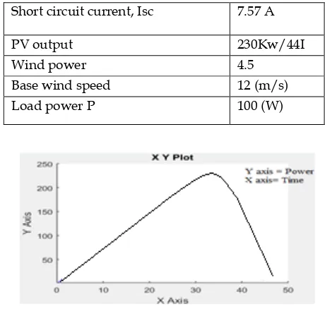
Open circuit voltage, Voc 0.62 V
Short circuit current, Isc 7.57 A
PV output 230Kw/44I
Wind power 4.5
Base wind speed 12 (m/s)
Load power P 100 (W)
Fig. 11 PV Characteristics
In figure 11 show PV characteristics of the solar cells and there are X-Y coordinates voltage Vs current plotted. The solar cell obtains the maximum power at 230 kW at the maximum VI point on current-voltage characteristic as shown in fig 11. Fig 11 The output of a Solar Panel. By measuring the current between the two shorted terminals we obtain the short circuit current.
1648
Fig 13 Vdc the direct cuurnt voltage output from Solar Panel
Fig.14 DC-DC Bidirectional Converter used for reducing Frequency perturbations in a multi agent smart grid
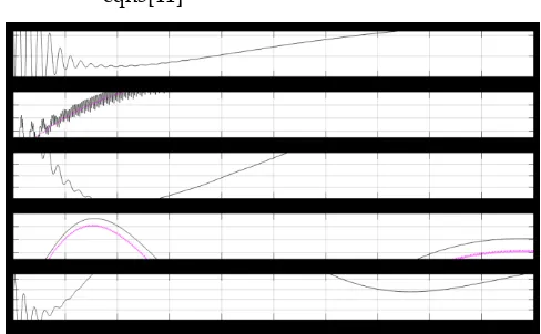
Wind Power Generation Turbine with Pitch angle Controller Fig.15 Wind Power
The above Fig 15 shows the Output power generated by wind generation turbine with a pitch angle controller.
Diesel Generator with Load Frequency Controller
Fig.16 Diesel Generator
Fig.17 O/p of a Diesel Generator with BSM
The above Fig. 16 and 17 Implements an output of a Diesel engine and governor system without and with a BSM. The input 1 is the measured speed, in rad/s. The input 2 is the reference speed, in pu. The output is mechanical power. The tf of the Controller is:
-eqn2[11]
The transfer function of the Throttle actuator is:
-eqn3[11]
Fig 18 Output Synchronous Generator
The above Fig 18 The output of a Synchronous Generator. Motor Time delay Td Inertia and viscous friction are modelled in the Synchronous generator.
Fig.19 Charging Current and voltage of Battery
Fig. 20 Linear Voltage and Current
The above Fig 20 Implements a three-phase parallel RLC load with linear Voltages and current. The primary benefits of the parallel three phase RLC load with linear current and voltages are the increase in fundamental components, better harmonic features, need of lesser power switch instruments and reduced switching losses.
Fig. 21 Nonlinear Voltage and Current
The above Fig 21 Parallel three-phase RLC load with Non-linear current and Voltage. This control architecture is employed for limiting the harmonic perturbations and for improving the stability of the system despite having mismatched outputs impedance present in the system. The outputs of the block are in Current or Voltage is in per-unit value.
4
C
ONCLUSIONWe have proposed a frequency stabilization method based on the double SMC for hybrid microgrid containing both conventional sources like Diesel generator and sustainable sources like photovoltaic and wind. The simulation studies show that even for a minute changes in the system frequency can be controlled. The hybrid microgrid with the proposed double SMC methods can achieve flexible output power control.
A
CKNOWLEDGMENTI owe my heartily thanks to my parents for their constant support and encouragement. Every Successful Research Work Requires a bounty amount of patience, a supreme guidance. I express my sincere thanks and heartily gratitude to my supervisor Mr. Shamsher Ansari I am thankful to my brother
Muhammad Tarique Yazdani.
R
EFERENCES[1] Rifkin, J., 2011. The third industrial revolution: how lateral power is transforming energy, the economy, and the world. Macmillan.
[2] Mariano, S.J.P.S.; Pombo, J.A.N.; Calado, M.R.A.; Ferreira, L.A.F.M. Optimal output control: Load frequency of a large power system. In Proceedings of the International Conference on Power Engineering, Energy and Electrical Drives, Lisbon, Portugal, 18–20 March 2009; pp. 369–374.
[3] Rashidi, M.; Rashidi, F.; Arjomand, A.S.; Sahragard, J. Design of a robust and adaptive load frequency controller for multi-area power networks with system parametric uncertainties using TDMLP neural network. In Proceedings of the IEEE International Conference on Systems, Man and Cybernetics, The Hague, The Netherlands, 10–13 October 2004; pp. 3698– 3703.
[4] Tomy, F.T. and Prakash, R., 2014. Load frequency control of a two area hybrid system consisting of a grid-connected PV system and thermal generator. technology, 3, p.4.
[5] Sadeh, J.; Rakhshani, E. Multi-area load frequency control in a deregulated power system using an optimal output feedback method. In Proceedings of the 5th International Conference on Electricity Market, Lisbon, Portugal, 28–30 May 2008; pp. 1–6. [6] Pahasa, J.; Ngamroo, I. Coordinated control of wind turbine
blade pitch angle and PHEVs using MPCs for load frequency control of microgrid. IEEE Syst. J. 2014, 99, 1–9.
[7] T. L. Vandoorn, J. D. M. De Kooning, B. Meersman, J. M. Guerrero and L. Vandevelde, ―Automatic Power-Sharing Modification of P/V Droop Controllers in Low-Voltage Resistive Microgrids‖, IEEE Transactions on Power Delivery, 27(4), (2012)
[8] Wang, C., Mi, Y., Fu, Y. and Wang, P., 2016. Frequency control of an isolated micro-grid using double sliding mode controllers and disturbance observer. IEEE Transactions on Smart Grid, 9(2), pp.923-930.
[9] Kumar, N.K. and Naidu, I.E.S., 2014. Load frequency control for a multi-area power system involving wind, hydro and thermal plants. International Journal of Innovative Research in Science, Engineering and Technology, 3(1), pp.1008-1013. [10]WondwosenEshetuPawan Sharma Charu Sharma ANFIS
based load frequency control in an isolated microgrid Published in 2018 IEEE International Conference on Industrial Technology (ICIT)Date of Conference: 20-22 Feb. 2018 ISBN recent Location Lyon, France
[11]R.Sebastian, J.Quesada, ―Distributed control system for frequency control in an isolated wind system, "Renewable Energy, vol. 31, no.3, pp. 285–305, Mar.2006.
[12]V. Ravikumar, A. Feliachi, ―Coordinated control of distributed energy resources to support load frequency control‖, Energy Conversion and Management, Vol.105, pp.918-928, November 2015.
1650 [14]W. D. Kellogg, M. H.Nehrir, G. Venkataramanan, V. Gerez,
"Generation unit sizing and cost analysis for stand-alone wind, photovoltaic, and hybrid wind/PV systems ", IEEE Transactions on Energy Conversion,vol.1 3, no.1, pp. 70-75, Mar. 1998.
[15]T. Senjyu, Y. Ochi, Y. Kikunaga, M. Tokudome, A.Yona, T. Funabashi, "Sensor-less maximum power point tracking control for wind generation system with squirrel cage induction generator‖, Renewable Energy, vol.34, pp. 994–999, Oct. 2009.