Available online: http://edupediapublications.org/journals/index.php/IJR/ P a g e | 4464
Asingle Phase Active Device for Power Quality Improvement
of Electric Field Transportation
Y. Rudraiah 1,S.Ankitha2
1
Assistant Professor, Laqshya institute of tech. & sciences, Khammam
2
PG Scholar, Laqshya institute of tech. & sciences, Khammam
Abstract: Problem statement: Now days, power quality has been given attention due to the intensive use of power electronic equipments in all types of industries such as steel, paper, textile industries and so on. These power electronic devices induce harmonic distortion into the supply lines which gives rise to many undesirable effects. Approach: This study presents a new method for harmonic and reactive power compensation with a Fuzzy logic controller and a new control algorithm for active power filter to eliminate harmonics and compensate the reactive power of three phase diode bridge rectifier with RL load. The Fuzzy logic controller was used to predict the reference current values and the firing pulses were generated using hysteresis current controller. The system was modeled and simulated using MATLAB/SIMULINK power system toolbox. Results: The total harmonic distortion for the system is reduced from 29.16-1.08% using the proposed fuzzy logic controller based shunt active filter. Conclusion: The simulation results found were quite satisfactory to eliminate harmonics and improve the power factor for non linearloads.
INTRODUCTION
Power quality is the ability of an electrical utility to provide electrical power without interruption and it encompasses any deviation from a perfect sinusoidal waveform. This includes transients, surges, sags, brownouts and harmonics. The growth in the use of non-linear loads has caused power quality problems like high current harmonics and low power factor (Chandra et al., 2000; George and Basu, 2008; Asiminoaeiet al., 2006). As it is becoming too important to prevent harmonic related problems, several harmonic standards have been developed and being followed by utilities worldwide. To avoid the effects of harmonics the passive filters and active filters are used. A passive filter has been a viable approach because of low cost and high efficiency. However, the passive scheme has limitations such as interference with the system impedance causing resonance with other networks and the inability to adapt to network characteristic variations (Wei et al.,2006).
Active filters have advantages over passive filters by utilizing a switch mode power electronic converter to supply harmonic currents equal to those in the load
currents (Singh and Singhal, 2007; Singh et al., 2007; Chatchanayuenyong, 2009) and also minimize the reactive power. Active filters have the ability to adjust the amplitude of the synthesized ac voltage of the inverters by means of PWM by control of dc link voltage, thus drawing either leading or lagging power from the supply. The active filter attempts to restore the sinusoidal characteristics of the line current by injecting the opposite harmonics demanded by the load. In order to produce the harmonic cancellation effect, the APF is connected in parallel with the load. The objective is to force the source current to be sinusoidal and in phase with the source voltage to have zero Total Harmonic Distortion (THD) and unitary power factor at the source line.
Generally, the performance of APF is based on design of VSI, type of the firing circuit and methods used for calculating the reference current (Sharmeelaet al., 2006). Several control algorithms and performance analysis were implemented using shunt active filter (Ajami and Hosseini, 2006; Kukrer and Komurcugil, 2008; Singh and Solanki, 2009; Zaveriet al., 2009; Rahmaniet al., 2010; Santiprapan and Areerak, 2010; Rani and Porkumaran, 2010). For power quality
control, a Fuzzy Logic Controller (FLC) Model gives comparatively better harmonic reduction than the conventional PI Controllers (Singh and Solanki, 2009; Zaveriet al., 2009; Ahmed et al., 2009; Rathika and Devaraj, 2010). The advantages of fuzzy control are that it does not require accurate mathematical model, can work with imprecise inputs, can handle nonlinearity and are more robust than other conventional nonlinear controllers (Ghasemiet al., 2008; Kerrouche and
Available online: http://edupediapublications.org/journals/index.php/IJR/ P a g e | 4465
SYSTEM CONFIGURATION
current controller is employed in the inner loop control to perform the reference current calculation.
PROPOSED CONTROL ALGORITHM The proposed control system of shunt active filter is concise and requires less computational efforts than many others found in the literature. It is formed by a DC voltage regulator and reference current estimator. Hysteresis controller is used for generating switching
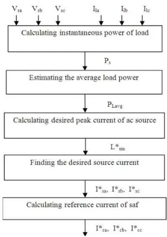
signals for SAF to force the desired current into the system. The purposes of using the active filter are to (i) correct the power factor, (ii) regulate the DC voltage and (iii) eliminate the line harmonics. The flow chart of the control algorithm is given Fig.2.
The compensating currents of active filter are determined by sensing the load currents, DC bus voltage and peak voltage of AC source (Vsm). The instantaneous voltages of AC source can be represented as in Eq. 1:
Vsa (t) Vsm sin(t)
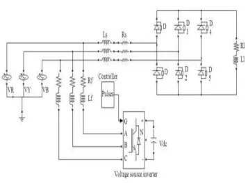
The basic system configuration of the shunt active Vsb (t) Vsm sin(t 120) (1) powerfilter is shown in Fig. 1. The Insulated-Gate
BipolarTransistor(IGBT)basedVoltageSourceInverter
Vsc (t) Vsm sin(t 240)
(VSI) bridges with a common DC bus capacitor areused as the SAF. A hysteresis rule based carrier less Pulse WidthModulation(PWM)currentcontrolisemployedto generatethegatingsignalstotheswitchingdevices.This system comprises three phase supply with diode bridge rectifier with RL as a non linear load (Chandra et al.,
The basic function of the proposed shunt active filter is to eliminate harmonics and compensate the current unbalance and reactive power of load. After compensating, the AC source feeds fundamental active power component of load current and losses of inverter for regulating the DC capacitor voltage and hence the peak of source reference current (I* ) has two 2000) and the proposed shunt active filter is connected
parallel to the system.
Only the load currents and source voltage are measured to force the line currents to be sinusoidal and in phase with the supply voltage. A proportional- integral voltage controller is used in the outer loop to
sm
components. The first component represents the average load active power (I*smp) and the second component of AC source current (I*smd) is obtained from DC capacitor voltage regulator. Instantaneous power of load (at kth sample) is given by Eq.2:
maintain the dc bus voltage constant. The FLC based Pload (k) Vsa (k)lla (k) Vsb (k)llb(k) Vsc (k)llc(k) (2)
Available online: http://edupediapublications.org/journals/index.php/IJR/ P a g e | 4466
n
where the difference between the reference value and the actual value is calculated and is given as:
V *cdc Vdcref Vcdc (7)
This (V*cdc) will be given to the controller to obtain I*smd. The desired peak current of AC source is then obtained by the following expression Eq.8:
l *sm l *smplsmd (8)
The AC source current must be sinusoidal and in- phase with source voltages. Therefore the desired currents ofACsourcecanbecalculatedbymultiplyingpeaksource current with unity sinusoidal signal and these unity signals areobtainedbythefollowingEq.9:
Fig. 2: The flow chart of the control algorithm
The average power of load (PLavg) is obtained by
Ua Vsa /
VsmUb Vsb /
VsmUc Vsc /
Vsm
The desired source current is given as Eq. 10: (9)
passing Pload (k) to low-pass filter. The average power l * l * U sa sm a
of load (PLavg) can be written by means of Eq. 3 and 4: l * l * U (10)
Plavg1/n
k1pload ( k )
nTfs ;T 1 / f
Where:
(3)
(4)
sb sm b
l *sc l *smUc
Finally, the reference currents of active filter can be obtained by subtracting the load current from the reference source current and given as follow Eq.11:
f = The fundamental system frequency l * l * l
ca sa la
fs = The samplingfrequency l * l * l (11)
In order to compensate the current harmonics and reactive power of load, the average active power of AC source must be equal to PLavg. Considering the unity power factor for AC source currents the average active power of AC source can be represented as Eq. 5:
cb sb lb
l *cc l *sc llc
These reference currents will be given to the switching circuit of carrier-less hysteresis controller for producing the necessary PWM pulse to the voltage source inverter. So thevoltage source inverter with theclosed
Ps 3 / 2Vsml *smpPlavg (5) loop system acts as a controlled current source and produces the exact reference waveform at the output.
From the average power of the load the first component of AC side current is obtained named I*smpand given as follows Eq. 6:
This output of the shunt active filter compensates the line harmonics and the line current becomes sinusoidal.
Role of DC side capacitor: When the APF is
compensating the harmonic and reactive power
l *smp 2 / 3PLavg /Vsm (6) components, the dc capacitor voltage Vdc varies. Hence Vdc is also sensed and regulated at a reference value The second component of AC source current (I*smd)is
obtainedfrom DC capacitor voltage regulator as in Eq. 7,
Available online: http://edupediapublications.org/journals/index.php/IJR/ P a g e | 4467
it maintains a dc voltage with small ripple in steady state and (ii) serves as an energy storage element to supply real power difference between load and source during transientperiod.
In steady state, the real power supplied by the source should be equal to the real power demand of the load plus a small power to compensate the losses in the active filter. Thus, the capacitor voltage can be maintained at a reference value. However, when the load condition changes the real power balance between the mains and the load will be disturbed. This real power difference is to be compensated by the dc capacitor. This changes the dc capacitor voltage away from the referencevoltage.
In order to keep a satisfactory operation of the active filter, the peak value of the reference current must be adjusted to proportionally change the real power drawn from the source. This real power charged/discharged by the capacitor compensates the real power consumed by the load. If the dc capacitor voltage is recovered and the reference voltage is attained, the real power supplied by the source is supposed to be equal to that consumed by the load. Thus, in this fashion the peak value of the reference source current can be obtained by regulating the average voltage of the dccapacitor.
When the dc capacitor voltage is smaller than the reference voltage, it indicates that the real power supplied by the source is not enough to supply load demand and hence the source current (i.e. the real power drawn from the source) needs to be increased. On the other hand, a larger value of dc capacitor voltage tries to reduce the reference source current. DC capacitor design can be represented as Eq.12-14:
2 2
ambiguous, imprecise, noisy, or missing input information. FL approach to control problems mimics how a person would make decisions, but much faster. The concept of Fuzzy Logic (FL) is a way of processing data by allowing partial set membership rather than crisp set membership or non-membership. FL incorporates a simple, rule-based IF X AND Y THEN Z approach to solve a control problem rather than attempting to model a systemmathematically.
The FLC mainly consists of three processes viz., Fuzzification, Inference and Defuzzification as shown in Fig.3.
Fuzzification: The fuzzy logic controller requires that each input/output variable which defines the control surface be expressed in fuzzy set notations using linguistic levels. The linguistic values of each input and output variable divide its universe of discourse into adjacent intervals to form the membership functions. The member value denotes the extent to which a variable belongs to a particular level. The process of converting input/output variable to linguistic levels is termed as fuzzification.
Inference: The behavior of the control surface which relates the input and output variables of the system are governed by a set of rules. A typical rule would be If X is A Then Y is B. When a set of input variables is read, each of the rules that have any degree of truth in its premise is fired and contributes to the forming of the control surface by approximately modifying it. When all the rules are fired, the resulting control surface is expressed as a fuzzy set to represent the constraint’s output. This process is known asinference.
Defuzzification: Defuzzification is the process of C 2E / V ref V min
Where:
Vref Vmax Vmin / 2
(12)
(13)
converting a fuzzy quantity into a crisp quantity. There are several methods available for defuzzification, centroid method being the most prevalent one which uses the following formula for defuzzification Eq. 15:
E1/2CV2
ref1.2 (14)
((x)x)dx
(x)dx(15)
FUZZY LOGICCONTROL where, µ is the membership degree of outputx. Fuzzy Logic (FL) is a problem-solving control
system methodology that lends itself to implementation in systems ranging from simple, small, embedded micro-controllers to large, networked, multi-channel PC or workstation-based data acquisition and control systems. It can be implemented in hardware, software, or a combination of both. FL provides a simple way to
Available online: http://edupediapublications.org/journals/index.php/IJR/ P a g e | 4468
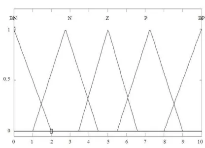
Fig. 4: Input membership function
Fig. 6: Hysteresis current control
Table 1: Fuzzy rulerepresentation
V Negative Zero Positive
I (N) (Z) (P)
Negative (N)
Zero
Big negative (BN) Negative
Positive (P) Zero
Big positive (BP) Positive
(Z) (N) (Z) (P)
Positive Big negative Negative Big positive
(P) (BN) (N) (BP)
Mamdani type fuzzy model was used for the implementation of the system. The input variables V1, V2 and V3 (ranging from -240-240V), I1, I2 and I3 (ranging from-10-10A) and the output variable I*smd(ranging from 0-10) were chosen. At the output defuzzification is done to obtain the crisp value. The relationship between the input and the output variable is chosen based on the Fuzzy rules representation table as shown in Table 1.
SWITCHING STRATEGY OF CONVERTER
Fig. 5: Output membership function
Fuzzy logic implementation: To design a FLC, the variables which can represent the performance of the system to be controlled should be chosen as input to the controller. For the given system, the proposed control algorithm is formed by using three source voltages and three load currents as its input, the same six parameters are taken as input to the FLC. In the dc voltage controller side, the capacitor voltage deviation is considered as the input of the FLC. The real power requirement in terms of the reference current is taken as the output of the FLC. The input and output variables are in crisp form and they have to be converted into linguistic variable form.
Gauss membership function is chosen as the input varies in the sinusoidal form and it has three subsets (shown in Fig. 4). Since the crisp value from the sensor cannot be given as input to the fuzzy logic controller, the membership functions are used to convert the crisp value into linguistic value. The output values vary within a small range and hence triangular membership function is chosen (shown in Fig.5).
Available online: http://edupediapublications.org/journals/index.php/IJR/ P a g e | 4469
Fig. 7: Hysteresis band
Hysteresis band is shown in Fig. 7. If upper switch is OFF and lower switch is ON in first-leg.
If upper switch is ON and lower switch is OFF in the second-leg.
Similarly the switching logic of other two phases (b and c) of the SAF is formulated, using the width of hysteresisband.
MATERIALS AND METHODS
Simulation was carried out to demonstrate the effectiveness of the proposed control strategy for the active filter to reduce the harmonics. The test system used to carry out the analysis (Fig. 1) consists of a three phase voltage source and a three phase diode bridge rectifier with RL load. The active filter is connected to the test system through an inductor L. The values of the circuit elements used in the simulation are given in Table 2. MATLAB/SIMULINK is used to simulate the test system and the proposed shunt active filter.
RESULTS
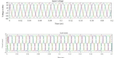
The three phase source voltage and current which is same as that of the load waveform without shunt active filer is shown in Fig.8.
The frequency spectrum of the distorted waveform is shown in Fig. 9 where Total Harmonic Distortion (THD) of the distorted line current is 20.75%. From the harmonic spectrum, it is evident that, the supply current is distorted due to the harmonics especially of fifth and seventh order.
An active filter with fixed hysteresis band current control (HB = 0.5A) and a PI voltage control is connected in parallel with the load. Figure 10 shows the source voltage and source current of the system with the PI based conventional controller. The THD in this case has decreased from 20.75-1.27%.
Fig. 8: Source voltage and current without filter
Table 2:Systemparameters
Parameters Value
Supplypeak voltage 56V
Supplyfrequency 50 Hz
Vdc 300mF
Lf 3mH
Rf 0.1Ω
Kp,Ki 0.001,0.1
Rs 0.25Ω
Ls 2.5mH
Rl 10 Ω and 5Ω
Ll 5mH
Average switchingfrequencyfs 20kHz
Table 3: Comparisonofresults THD(%)
---
Method R phase Y phase B phase
Without filter 29.16 29.13 29.14
Without FLC based filter 1.27 1.30 1.29
With FLC based filter 1.08 1.12 1.06
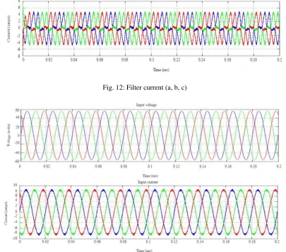
To reduce the harmonics further, the active filter was simulated with fuzzy logic based controller. Figure 11 shows the compensating current to be generated by using the proposed algorithm and the actual filter current that is injected in to the system is shown in Fig.
12. After the filter current is injected into the line, the source voltage and current waveforms are as shown in Fig. 13 and the frequency spectrum of the compensated current is shown in Fig.14.
The performance of the active filter with the proposed control algorithm is found to be satisfactory and the source current is eventually sinusoidal and it isin-phase with the supply voltage as shown in Fig.
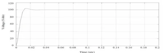
13. The THD has decreased from 20.75-1.08% with fuzzy logic controller. Figure 15 shows the DC capcitor voltage for the shunt active power filter and it is clear that the controller is able to regulate the voltage requirement of the active filter. The Table 3 shows the percentage THD of supply current for PI
Available online: http://edupediapublications.org/journals/index.php/IJR/ P a g e | 4470
Fig. 9: Frequency spectrum of source current (R-phase) without filter
Fig. 10: Source voltage and current with PI based filter
Available online: http://edupediapublications.org/journals/index.php/IJR/ P a g e | 4471
Fig. 12: Filter current (a, b, c)
Fig. 13: Source voltage and source current with filter (a, b, c)
Available online: http://edupediapublications.org/journals/index.php/IJR/ P a g e | 4472
Fig. 15: DC capacitor voltage
DISCUSSION
In this study, a fuzzy logic based current controller strategy is used to regulate the filter current to ensure harmonic free supply current. The simulation is carried out in the MATLAB/SIMULINK environment and the performance was analyzed in a sample power system with a source and a diode rectifier with a R load as a non-linear one. Fuzzy Logic Controller (FLC) Model provides comparatively better harmonic reduction than the conventional PI Controllers and the reactive power requirement from the source has been reduced and the input power factor is been improved.
CONCLUSION
A fuzzy logic based current controller strategy is used to regulate the filter current to ensure harmonic free supply current. The active filter was simulated using MATLAB/SIMULINK and the performance was analyzed in a sample power system with a source and a non-linear load. For power quality control, a Fuzzy Logic Controller (FLC) Model provides comparatively better harmonic reduction than the conventional PI Controllers. The FLC based controller has quick response and more robust than other conventional nonlinear controllers. The simulation results show that for the given system the proposed controller reduces total harmonic distortion below the value recommended by IEEE 519standard.
[1] L. Jun-Young and C. Hyung-Jun, “6.6-kW onboard charger design using DCM PFC converter with harmonic modulation technique and two-stage dc/dc converter,” IEEE Trans. Ind. Electron., vol. 61, no. 3, pp. 1243– 1252, Mar. 2014.
[2] R. Seung-Hee, K. Dong-Hee, K. Min-Jung, K. Jong-Soo, and L. ByoungKuk, “Adjustable frequency duty-cycle hybrid control strategy for fullbridge series resonant converters in electric
vehicle chargers,” IEEE Trans. Ind. Electron., vol. 61, no. 10, pp. 5354–5362, Oct. 2014.
[3] P. T. Staats, W. M. Grady, A. Arapostathis, and R. S. Thallam, “A statis-tical analysis of the effect of electric vehicle battery charging on distribu-tion system harmonic voltages,” IEEE Trans. Power Del., vol. 13, no. 2,pp. 640–646, Apr. 1998.
[4] A. Kuperman, U. Levy, J. Goren, A. Zafransky, and A. Savernin, “Batterycharger for electric vehicle traction battery switch station,” IEEE Trans.Ind.Electron., vol. 60, no. 12, pp. 5391–5399, Dec. 2013.
[5] Z. Amjadi and S. S. Williamson, “Modeling, simulation, control of an advanced Luo converter for plug-in hybrid electric vehicle energy-storage system,” IEEE Trans. Veh. Technol., vol. 60, no. 1, pp. 64–75, Jan. 2011.
[6] H. Akagi and K. Isozaki, “A hybrid active filter for a three-phase 12-pulse diode rectifier used as the front end of a medium-voltage motor drive,” IEEE Trans. Power Del., vol. 27, no. 1, pp. 69–77, Jan. 2012.
[7] A. F. Zobaa, “Optimal multiobjective design of hybrid active power filters considering a distorted environment,” IEEE Trans. Ind. Electron., vol. 61, no. 1, pp. 107–114, Jan. 2014.
[8] D. Sixing, L. Jinjun, and L. Jiliang, “Hybrid cascaded H-bridge converter for harmonic current compensation,” IEEE Trans. Power Electron., vol. 28, no. 5, pp. 2170–2179, May 2013.
[9] M. S. Hamad, M. I. Masoud, and B. W. Williams, “Medium-voltage 12-pulse converter: Output voltage harmonic compensation using a series APF,” IEEE Trans. Ind. Electron., vol. 61, no. 1, pp. 43–52, Jan. 2014.
Available online: http://edupediapublications.org/journals/index.php/IJR/ P a g e | 4473
Mr. Y. RUDRAIAH was born in India in the year of 1988. He received B.Tech degree in Electrical and Electronics Engineering in the year of 2009 & M.Tech in Power Electronics & Electrical Drives in the year of 2011 from JNTUH, Hyderabad. He is expert in Electrical circuits, Electrical Machines, and Power system Subjects. He is currently working as An Assistant Professor in EEE Department in Laqshya Institute of Technology and Sciences, Khammam,Telangana State ,India.
mail id: [email protected]
SAMBHANI ANKITHA (POWER ELECTRONICS ) PURSUING In laqshya Institute of Technology sciences ,TALIKELLA(V) ,KHAMMAM, TELANGANA, INDIA