Scholarship@Western
Scholarship@Western
Electronic Thesis and Dissertation Repository
5-2-2012 12:00 AM
Multi-stage Wireless Signal Identification for Blind Interception
Multi-stage Wireless Signal Identification for Blind Interception
Receiver Design
Receiver Design
Gejie Liu
The University of Western Ontario
Supervisor Xianbin Wang
The University of Western Ontario
Graduate Program in Electrical and Computer Engineering
A thesis submitted in partial fulfillment of the requirements for the degree in Master of Engineering Science
© Gejie Liu 2012
Follow this and additional works at: https://ir.lib.uwo.ca/etd
Recommended Citation Recommended Citation
Liu, Gejie, "Multi-stage Wireless Signal Identification for Blind Interception Receiver Design" (2012). Electronic Thesis and Dissertation Repository. 516.
https://ir.lib.uwo.ca/etd/516
This Dissertation/Thesis is brought to you for free and open access by Scholarship@Western. It has been accepted for inclusion in Electronic Thesis and Dissertation Repository by an authorized administrator of
for Blind Interception Receiver Design
(Spine title: Blind Signal Identification)
(Thesis format: Monograph)
by
Gejie Liu
Graduate Program in
Engineering Science
Electrical and Computer Engineering
A thesis submitted in partial fulfillment of the requirements for the degree of
Master of Engineering Science
School of Graduate and Postdoctoral Studies The University of Western Ontario
London, Ontario, Canada
c
THE UNIVERSITY OF WESTERN ONTARIO
SCHOOL OF GRADUATE AND POSTDOCTORAL STUDIES
CERTIFICATE OF EXAMINATION
Chief Advisor: Examining Board:
Dr. Xianbin Wang Dr. Serguei L. Primak
Dr. Abdallah Shami
Dr. Liying Jiang
The thesis by
Gejie Liu
entitled:
Multi-stage Wireless Signal Identification for Blind Interception Receiver
Design
is accepted in partial fulfillment of the
requirements for the degree of
Master of Engineering Science
Date:
Chair of Examining Board Dr. Luiz Capretz
ii
Protection of critical wireless infrastructure from malicious attacks has become
in-creasingly important in recent years, with the widespread deployment of various
wire-less technologies and dramatic growth in user populations. This brings substantial
technical challenges to the interception receiver design to sense and identify various
wireless signals using different transmission technologies. The key requirements for the receiver design include estimation of the signal parameters/features and
classifica-tion of the modulaclassifica-tion scheme. With the proper identificaclassifica-tion results, corresponding
signal interception techniques can be developed, which can be further employed to
enhance the network behaviour analysis and intrusion detection.
In detail, the initial stage of the blind interception receiver design is to identify
the signal parameters. In the thesis, two low-complexity approaches are provided
to realize the parameter estimation, which are based on iterative cyclostationary
analysis and envelope spectrum estimation, respectively. With the estimated signal
parameters, automatic modulation classification (AMC) is performed to automati-cally identify the modulation schemes of the transmitted signals. A novel approach is
presented based on Gaussian Mixture Models (GMM) in Chapter 4. The approach is
capable of mitigating the negative effect from multipath fading channel. To validate
the proposed design, the performance is evaluated under an experimental propagation
environment. The results show that the proposed design is capable of adapting blind
parameter estimation, realize timing and frequency synchronization and classifying
the modulation schemes with improved performances.
I present my sincerest appreciation to those who made this thesis possible. I would like to first thank my supervisor, Dr. Xianbin Wang, whose encouragement and support from the initial to the final level enabled me to develop a solid understanding of this subject. His guidance and freedom encouraged me to endeavor into this new research area. It has been a true fortune and privilege working with him.
I also owe my deepest gratitude to Dr. Serguei L. Primak and Dr. Vijay Parsa for whose courses greatly improved my work in theoretical analysis, understanding of communication systems, and signal processing.
At the same time, I would like to thank Dr. Abdelkader Ouda, Dr. Reza Azarderakhsh and Dr. Mohammed Alqedra. It is an honor to work as a teaching assistant under their guidance. I also want to thank Graduate Assistant and librarians in Allyn & Betty Taylor Library and The D. B. Weldon Library for their work and help.
Specially, I am indebted to my parents. Even far away, they have been present and supportive through every step of my study, always providing help in difficult times, and enjoying every single accomplishment during my fighting journey.
Lastly, I offer my regards and blessings to all of those who supported me in any respect during the completion of this study.
Certificate of Examination . . . . ii
Abstract . . . . iii
Acknowledgements . . . . iv
List of tables . . . viii
List of figures . . . . ix
Acronyms . . . . x
1 Introduction . . . . 1
1.1 Motivation . . . 1
1.2 Objective . . . 3
1.3 Thesis Contributions . . . 4
1.4 Thesis Organization . . . 6
2 Blind Signal Identification with Iterative Cyclostationary Analysis 8 2.1 OFDM Systems . . . 9
2.1.1 General Structure . . . 9
2.1.2 Implementation . . . 11
2.1.2.1 Guard Time and Cyclic Extension . . . 12
2.1.2.2 Windowing . . . 14
2.2 Cyclostationary Signal Analysis . . . 16
2.3 Blind Parameter Estimation . . . 19
2.4 Introduction of the Proposed Approach . . . 22
2.5 System Model . . . 23
2.5.1 Oversampled OFDM System Model . . . 24
2.5.2 Cyclostationary Analysis in Oversampled OFDM Signals . . . 25
2.6 Iterative Cyclostationary Analysis with Arbitrary Oversampling Ratio 27 2.7 Parameter Estimation Based on Detected Cyclostationary Feature . . 31
2.8 Enhanced Channel Estimation with System Parameters Estimation . 33 2.8.1 Pilot Block Detection . . . 33
2.8.2 Iterative Channel Estimation . . . 33
2.9 Simulation Results and Discussions . . . 35
2.9.1 Enhanced iterative channel estimation . . . 37
2.9.2 Complexity Analysis . . . 38
2.10 Conclusion . . . 40
3 Joint Blind Signal Parameter Estimation and Synchronization . . 42
3.1 Synchronization for OFDM System . . . 42
3.1.1 Timing Offset Estimators . . . 43
3.1.1.1 Schmidl′s Method . . . 43
3.1.1.2 Minn′s Method . . . 44
3.1.1.3 Park′s Method . . . 45
3.1.1.4 Seung′s Method . . . 46
3.1.2 Carrier Frequency Offset and Sampling Clock Offset Estimator 47 3.1.2.1 One Dimensional Linear Least Square Estimation . . 47
3.1.2.2 D-Symbols Delay linear Least Square Estimation . . 48
3.1.2.3 Two Dimensional Linear Least Square Estimation . . 49
3.2 Introduction of the Proposed Approach . . . 50
3.3 System Model . . . 52
3.4 Envelope Spectrum-based Oversampling Ratio Estimation . . . 54
3.5 Joint Iterative Blind Parameter Estimation and Synchronization . . . 57
3.5.1 Estimation of the Number of Subcarriers and CP Length . . . 57
3.5.2 Estimation of Carrier Frequency Offset and Timing Offset . . 59
3.6 Experimental Results . . . 61
3.6.1 Lab Testing Platform . . . 61
3.6.2 Experimental Results . . . 63
3.7 Conclusion . . . 64
4 GMM-based Automatic Modulation Classification . . . . 67
4.1 Automatic modulation classification . . . 67
4.1.1 Decision Theoretic-based Automatic Modulation Classification 69 4.1.1.1 ALRT-based Algorithms . . . 71
4.1.1.2 GLRT- and HLRT-based Algorithms . . . 73
4.1.2 Pattern Recognition-based Automatic Modulation Classification 74 4.1.2.1 Instantaneous Features-based Algorithms . . . 74
4.1.2.2 Wavelet Transform-based Algorithm . . . 76
4.1.2.3 Signal statistics-based Algorithms . . . 77
4.2 Introduction of the Proposed Approach . . . 79
4.3 Background . . . 81
4.3.1 Gaussian Mixture Models (GMM) . . . 82
4.3.2 Kullback-Leibler (K-L) Divergence . . . 83
4.4 GMM-based Modulation Classification . . . 85
4.4.1 Signal Features Extraction . . . 86
4.4.2 Modulation Classification Using GMM . . . 88
4.5 Iterative MAP Channel Mitigation Modulation Classification . . . 90
4.6 Simulation Results and Discussions . . . 93
4.7 Conclusion . . . 94
5 Conclusion . . . . 97
5.1 Contributions of This Thesis . . . 97
5.2 Future Works . . . 99
References . . . 101
Curriculum Vitae . . . 111
2.1 Physical layer parameters. . . 13
2.2 Complexity needed for the proposed method and traditional estimation. 39 3.1 PAPR Comparison . . . 43
3.2 System Parameters for The Generated OFDM Signals. . . 62
4.1 Theoretical Values Θ of GMM forAnor . . . 83
4.2 Theoretical Values Θ of GMM forσ . . . 84
2.1 OFDM modulator. . . 11
2.2 Block diagram of an OFDM transceiver. . . 13
2.3 OFDM frame with cyclic extension and windowing . . . 15
2.4 SCF estimate for a baseband OFDM signal. . . 27
2.5 SCF for oversampling ratioq = 2.85. . . 28
2.6 Cyclic autocorrelation test for CP length estimator at fixed τ =Ns. . 32
2.7 Different power levels allocated to the pilot block and data block . . . 34
2.8 MSE of oversampling rateq under multipath channel(SNR = 10dB). 37 2.9 Prob. of the estimation error of number of subcarriers and CP length. 38 2.10 MSE of Enhanced Channel Estimation with different estimation error 41 2.11 SER of signal detection with different parameter estimation error . . 41
3.1 The principle of D-symbol estimation. . . 48
3.2 Illustration of oversampling structure for blind parameter estimation. 53 3.3 Spectrum information of oversampled OFDM signal (q= 4) . . . 56
3.4 Instrument setups for lab testing platform. . . 62
3.5 Mean square error of iterative oversampling ratioq. . . 64
3.6 Prob. of correct estimation of number of subcarriers and CP length. . 65
3.7 BER of the proposed joint parameter estimation and synchronization. 66 4.1 γmax for different modulation schemes when SNR = 5dB. . . 87
4.2 σmax for different modulation schemes SNR = 5dB. . . 88
4.3 The block diagram for GMM-based modulation classification. . . 89
4.4 Comparison of GMM and HOS onPcc for 16QAM and 2FSK. . . 94
4.5 Comparison of GMM and HOS onPcc for BPSK and 2ASK. . . 95
AWGN Additive White Gaussian Noise
ASK Amplitude Shift Keying
ACF Autocorrelation Function
AMC Automatic Modulation Classification
ALRT Average Likelihood Ratio Test
CFO Carrier Frequency Offset
CP Cyclic Prefix
CR Cognitive Radio
CS Cyclic Spectrum
DFT Discrete Fourier Transform
EM Expectation-Maximization
FDM Frequency Division Multiplexing
FSK Frequency Shift Keying
GMM Gaussian Mixture Model
GLRT Generalized Likelihood Ratio Test
HLRT Hybrid Likelihood Ratio Test
LF Likelihood Functions
MAP Maximum A Posteriori
ML Maximum Likelihood
OFDM Orthogonal Frequency Division Multiplexing
PSK Phase Shift Keying
PDF Probability Density Functions
QAM Quadrature Amplitude Modulation
QPSK Quadrature Phase Shift Keying
SDR Software Defined Radio
SFC Sliding Frequency Correlator
SFO Sampling Frequency Offset
WT Wavelet Transform
Chapter 1
Introduction
1.1
Motivation
Protection of critical wireless infrastructure has become increasingly important in
recent years with the widespread deployment of various wireless technologies and
dramatic growth in user populations. Wireless communication systems and networks
suffer from various security threats, including attacks similar to those in wired
net-works and those which are specific to the wireless environment. Wireless
communi-cation signals are open to intrusion from the outside without the need for a physical
connection and, as a result, some techniques that provide to a wired network have
proven to be inadequate in wireless networks. This brings substantial technical
chal-lenges to the spectrum regulation enforcement oriented signal sensing practice, due to
the inherent difficulties in obtaining the content, identification and network behaviour
of a signal of interest through conventional spectral analysis only.
The primary motivation of this study is to further develop the necessary
en-abling technologies required for blind interception receiver design to protect the
wire-less infrastructure and improve its resilience to various attacks. Proper RF signal
sensing and identification, modulation classification are essential to protecting the
public services against illegal usage of wireless communications and malicious attacks
Consequently, the study is dedicated to develop a software defined radio (SDR) based
interception receiver to enhance the security of wireless communications, with novel
multi-stage RF signal identification techniques. The proposed receiver will be
capa-ble of identifying, intercepting and analyzing the signal of interest, and reconfiguring
its operating parameters depending on the operational objectives of respective user
groups.
Another motivation for the thesis work is for cognitive radio application. With
the recent rapid growth in wireless applications and systems, the problem of
spec-trum utilization has become more critical than ever before. As an emerging solution,
Cognitive Radio (CR) systems aim to improve the efficiency of spectrum usage with
the principle of sharing the available spectrum resources adaptively. Orthogonal
fre-quency division multiplexing, which has been known to be one of the most effective
multicarrier techniques, has attracted significant attention in the development of CR
systems due to its high spectral efficiency and flexibility in allocating transmission
resources in dynamic environments.
However, the existence of dissimilar wireless transmission schemes poses a
chal-lenge to the design of CR receivers that can operate with the multi-waveform signals.
Therefore, blind system parameter estimation is of significant importance for reliable
communication in CR environments. Furthermore, blind estimation is also helpful
to reduce signaling overhead in the case of adaptive transmission where the system
parameters change depending on the environmental characteristics or the spectrum
availability. The capability of identifying system parameters is necessary for spectrum
survey with the purpose of monitoring the systems to discover illegal transmissions
as well.
Relevant signal identification are originated from SDR, where initial mode
to identify the user air interface. Once connected, an SDR has to monitor alternative
air interfaces to be able to perform inter-standard handover if necessary. To be
spe-cific, the signal detection could be realized through signal sensing and identifications
which are widely used in cognitive radio communications. Signal sensing provides the
capability to sense, learn, and discover the parameters related to the radio channel
characteristics, availability of spectrum and operating environment, user requirements
and applications, and network availability
1.2
Objective
In order to realize the multi-stage signal identification for blind interception receiver
design, blind parameter estimation, synchronization and modulation classification are
the primary objectives in this study.
To be specific, the first step is to identify the primary parameters of the
in-coming signal. Since Orthogonal Frequency Division Multiplexing (OFDM) system
is primarily considered in the study, the key system parameters we select here are
sampling frequency, number of subcarriers, cyclic prefix ratio as well as frequency and
timing offset. Since two directions exist in literature for blind parameter estimation,
which are nonparametric spectrum based and cyclostationarity based, we analyze the
performance for both and develope the approaches to improve the estimation
accu-racy under two scenarios. With the aid of estimated parameters, Carrier frequency
offset (CFO) and timing offset are estimated for the purpose of synchronization. An
iterative scheme is employed to increase the estimation accuracy.
Automatic modulation classification (AMC) is used to automatically identify
the modulation schemes used in an intercepted communication signal by analyzing
and fading channels. The interest in blind modulation classification has been growing
since the late eighties. It plays several important roles in both civilian and
mili-tary applications including signal surveillance, data interception, and confirmation
of signal identification, interference monitoring, and counter-measure development.
Legitimate signals should be securely transmitted and received, whereas hostile
sig-nals from adversaries must be located, identified, and recovered. The transmitting
frequencies of these signals may range from high frequency to millimetre frequency
band and their format can vary from traditional simple narrowband modulations to
newly introduced wideband schemes particularly OFDM. Under such diverse
condi-tions, advanced techniques are needed for real-time signal interception and processing,
which are vital for decisions involving electronic warfare operations and other actions.
Furthermore, the lab testing platform is introduced in the thesis to verify the
proposed algorithms of blind parameter estimation and modulation classification.
The hardware environments include an arbitrary vector signal generator, spectrum
analyzer and high speed signal acquisition system. Our proposed algorithms for blind
OFDM system parameter estimations and modulation classification are evaluated
using the signal generated from Rohde & Schwarz (R&S) and National Instruments
(NI) signal acquisition system.
1.3
Thesis Contributions
The main contributions of this thesis are summarized as follows:
• In this study, we present an iterative scheme for blind parameter estimation of
OFDM interception receiver design, which is based on cyclostationary feature
detection. The approach avoids the exploration of a wide range of cyclic
interest and performing high resolution exploration in that region to accurately
detect the feature. Based on the detected features, system parameter estimation
(sampling frequency, number of subcarriers and Cyclic Prefix (CP) duration)
can be successfully obtained which provide the essential information for blind
identification.
• An iterative blind parameter estimation and synchronization offset cancellation
scheme is proposed in the study to perform accurate signal sampling and
param-eters identification. Specifically, the arbitrary oversampling ratio is estimated
at first through time-domain envelope spectrum information, based on which
the other system parameters, including the number of subcarriers and the CP
length, are calculated sequentially. Synchronization is obtained from the
esti-mated parameters and an iterative algorithm is employed to refine the results
until a certain threshold is reached.
• With the purpose of modulation classification, a Gaussian Mixture Model
(GMM)-based offline database is established, containing the parameters for different
modulation schemes, as the reference to determine the GMM parameters of the
received signal. Similar work has been investigated before without considering
multipath fading channels. In the thesis, an iterative Maximum A Posteriori
(MAP) channel mitigation technique is introduced to mitigate the multipath
fading as well as to maintain system performance. Kullback-Leibler (K-L)
Di-vergence is employed to measure the distance between the received signal and
the modulation schemes in the database. To further ease the computational
complexity, Gaussian approximation is carried out to cope with multivariate
Gaussian components. Performance analysis is presented using Monte Carlo
1.4
Thesis Organization
The organization of this thesis is as follows:
In Chapter 2, a low-complexity approach, with the capability of blind OFDM
parameter estimation, is proposed. The design is based on cyclostationary feature
detection over a selected cyclic spectrum range using iterative techniques, instead of
an exploration of the entire spectrum. Therefore, the computational complexity of
signal interception is dramatically reduced. Monte Carlo simulations are conducted
to evaluate the performance of the individual modules as well as the interception
receiver. Numerical results show that the proposed algorithm is capable of signal
detection in blind scenarios with improved performance.
In Chapter 3, an iterative design method for OFDM system parameter
estima-tion and synchronizaestima-tion under a blind scenario for cognitive radio systems is
pro-posed here. A novel envelope spectrum based arbitrary oversampling ratio estimator
is presented first, based on which the algorithms are then developed to provide the
identification of other OFDM parameters (number of subcarriers, cyclic prefix (CP)
length). CFO and timing offset are estimated for the purpose of synchronization with
the help of the identified parameters. An iterative scheme is employed to increase the
estimation accuracy. To validate the proposed design, the performance is evaluated
under an experimental propagation environment and the results show that the
pro-posed design is capable of adapting blind parameter estimation and synchronization
for cognitive radio with improved performances.
Chapter 4 considers the classification of digital modulation schemes in the
pres-ence of multipath fading channels and additive noise. The chapter presents a novel
modulation recognition approach based on GMM. The basic procedure involves
the received signal into different modulation schemes based on the database by
us-ing K-L Divergence. In order to mitigate the negative impact from multipath fadus-ing
channels, an iterative MAP-based channel estimation is used in conjunction with the
Expectation-Maximization (EM) algorithm. Furthermore, Gaussian approximation
is carried out to decrease the computational complexity. Monte Carlo simulations are
conducted to evaluate the performance of individual modulation scheme classification.
Numerical results show that the proposed approach is capable of recognizing various
modulated signals with improved performance under Additive white Gaussian noise
(AWGN) and multipath fading channels.
Finally, conclusions are drawn and future works are discussed in Chapter 5.
Notations: An upper (lower) case boldfont letter represents a matrix (column
vector). The superscripts T and H denote the transpose and the Hermitian
trans-pose, respectively. [X]i,j denotes the (i, j)th element of matrix X. The term y(n)
denotes thenth element of vectory. T r(·),E(·), andR(·) stand for the matrix trace,
the expectation, the real part and the imaginary part, respectively. |y| denotes the
Euclidean norm of y. diag(x1, x2, ..., xN) represents a diagonal matrix whose lth
di-agonal element is xl while diag(X) denotes a vector of the diagonal elements of X.
Chapter 2
Blind Signal Identification with Iterative
Cyclostationary Analysis
Although cyclostationary analysis of OFDM signals has been widely explored for
spectrum sensing and signal identification, the associated high computational
com-plexity requires additional processing and detection time, which further prevents the
related techniques from fulfilling the demands of real-time military applications. In
addition, recognizable and distinctive features of an OFDM signal in standards-based
civilian communications may not be available in military communications thus,
pos-ing a challenge for accurate identification of the OFDM system parameters. In this
chapter, a low-complexity interception receiver, with the capability of blind OFDM
parameter estimation, is proposed. The interception receiver design is based on
cy-clostationary feature detection over a selected cyclic spectrum range using iterative
techniques, instead of an exploration of the entire spectrum. Therefore, the
com-putational complexity of signal interception is dramatically reduced. Monte Carlo
simulations are conducted to evaluate the performance of the individual modules as
well as the interception receiver. Numerical results show that the proposed algorithm
2.1
OFDM Systems
OFDM is a wideband digital communications technique in which high-rate data is
transmitted in parallel via multiple orthogonal subcarriers. In 1966, the idea of
multi-carrier transmission was first brought out by Chang in [1]. Weinstein and
Ebert subsequently proposed a complete digital OFDM system that used discrete
Fourier transform (DFT) and inverse DFT (IDFT) for baseband modulation and
demodulation [2] in 1971. From then on, OFDM systems have been investigated
for wideband communications over mobile radio channels [3]. In this chapter, the
transmitter and receiver structures for OFDM systems are presented in the sequel.
Moreover, the main merits and drawbacks of OFDM system are summarized, followed
by the major applications of OFDM systems.
The usage OFDM for high data transmissions has been investigated due to its
its high spectral efficiency and robustness to multi-path interference. OFDM is an
extension to the conventional frequency division multiplexing (FDM) with respect to
spectrum usage. In FDM, many parallel carriers are modulated and transmitted in
different frequency bands to different users simultaneously. To avoid band interference
caused by spectral leakage in conventional FDM, guard bands are inserted between
two adjacent frequency bands. However, the utilization rate of available frequency
spectrum drops due to the insertion of guard bands. To cope with this inefficient
bandwidth usage, OFDM technique was proposed, in which adjacent subcarriers are
overlapped orthogonally without interfering each other.
2.1.1
General Structure
The basic principle of OFDM is to split a high-rate datastream into a number of lower
relative amount of dispersion in time caused by multipath delay spread is decreased
because the symbol duration increases for lower rate parallel subcarriers. The other
problem to solve is the intersymbol interference, which is eliminated almost completely
by introducing a guard time in every OFDM symbol. This means that in the guard
time, the OFDM symbol is cyclically extended to avoid intercarrier interference.
An OFDM signal is a sum of subcarriers that are individually modulated by
using phase shift keying (PSK) or quadrature amplitude modulation (QAM). The
symbol can be written as:
s(t) = Re Ns 2 ∑
i=−Ns2
di+N
s/2exp(j2π(fc−
i+ 0.5
T )(t−ts))
, ts≤t ≤ts+T
s(t) = 0, t < ts and t > ts+T
(2.1)
where:
Ns is the number of subcarriers
T is the symbol duration
fc is the carrier frequency
The equivalent complex baseband notation is given by:
s(t) =
Ns
2 ∑
i=−Ns2
di+Ns/2exp(j2π(i
T)(t−ts)), ts ≤t≤ts+T
s(t) = 0, t < ts and t > ts+T
(2.2)
In this case, the real and imaginary parts correspond to the in-phase and
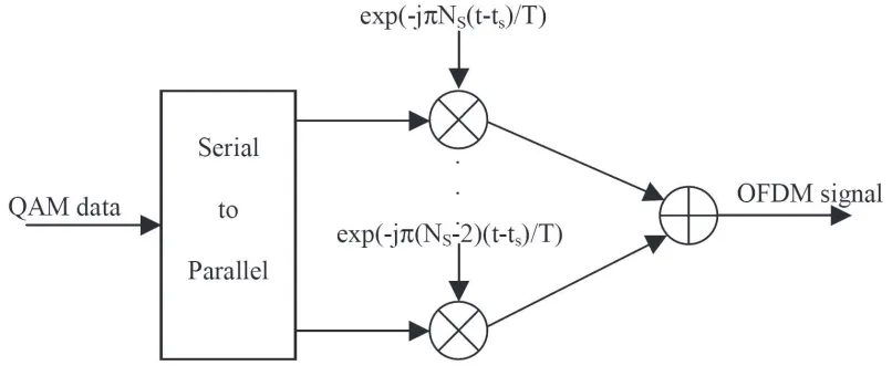
the desired frequency to produce the final OFDM signal. Figure 2.1 shows the block
diagram for the OFDM modulator.
Figure 2.1: OFDM modulator.
The complex baseband OFDM signal defined the equation (2.2) is the inverse
Fourier transform of Ns QAM input symbols. The time discrete case is the inverse
discrete Fourier transform. In practice, this transform can be implemented very
efficiently by the inverse fast Fourier transform (IFFT). The IFFT drastically reduces
the amount of calculations by exploiting the regularity of the operations in the IDFT.
2.1.2
Implementation
In practice, the OFDM signal for the standard IEEE 802.11a is generated as follows:
In the transmitter, binary input data is encoded by a rate 1/2 convolutional encoder.
The rate can be increased to 2/3 and 3/4. After interleaving, the binary values are
converted to QAM values. Four pilot values are added each 48 data values, resulting
in a total of 52 QAM values per OFDM symbol. The symbol is modulated onto 52
subcarriers by applying the Inverse Fast Fourier Transform (IFFT). The output is
mul-tipath propagation. Windowing is applied after to get a narrower output spectrum.
Using an IQ modulator, the signal is converted to analog, which is upconverted to
the 5 GHz band, amplified, and transmitted through the antenna.
Basically, the receiver performs the reverse operations of the transmitter, with
additional training tasks. In the first step, the receiver has to estimate frequency offset
and symbol timing, using special training symbols in the preamble. After removing
the cyclic extension, the signal can be applied to a Fast Fourier Transform to recover
the 52 QAM values of all subcarriers. The training symbols and the pilot subcarriers
are used to correct for the channel response as well as remaining phase drift. The
QAM values are then demapped into binary values, and finally a Viterbi decoder
decodes the information bits.
Figure 2.2 shows the block diagram of an OFDM modem, including the
trans-mitter and the receiver. The IFFT modulates a block of input QAM values onto a
number of subcarriers. In the receiver, the subcarriers are demodulated by the FFT,
which is the reverse operation of the IFFT. These two operations are almost identical.
In fact, the IFFT can be made using an FFT by conjugating input and output of
the FFT and dividing the output by the FFT size. This makes it possible to use the
same hardware for both the transmitter and the receiver. Of course, this saving in
complexity is only possible when the modem does not have to transmit and receive
simultaneously, which is the case for the standard.
In case of the standard IEEE 802.11a, the parameters for the physical layer
(e.g. for OFDM) are listed in Table 2.1
2.1.2.1 Guard Time and Cyclic Extension
One of the most important problems in for wireless communications is the multipath
Figure 2.2: Block diagram of an OFDM transceiver.
Table 2.1: Physical layer parameters.
Data rate Modulation Coding rate Coded bits Coded bits Data bits
(Mbits/s) (R) subcarrier per symbol per symbol
(NBP SC) (NCBP S) (NDBP S)
6 BPSK 1/2 1 48 24
9 BPSK 3/4 1 48 36
9 BPSK 3/4 1 48 36
12 QPSK 1/2 2 96 48
18 QPSK 3/4 2 96 72
24 16-QAM 1/2 4 192 96
36 16-QAM 3/4 4 192 144
48 64-QAM 2/3 6 288 192
54 64-QAM 3/4 6 288 216
that the input datastream is divided in NS subcarriers and the symbol duration
is made NS times smaller, which also reduces the relative multipath delay spread,
relative to the symbol time, by the same factor.
a guard time for a each OFDM symbol. The guard time is chosen larger than the
expected delay spread such that multipath components from one symbol cannot
inter-fere with the next symbol. This guard time could be no signal at all but the problem
of intercarrier interference (ICI) would arise. Then, the OFDM symbol is cyclically
extended in the guard time. Using this method, the delay replicas of the OFDM
symbol always have an integer number of cycles within the FFT interval, as long as
the delay is smaller than the guard time. Multipath signals with delays smaller than
the guard time cannot cause ICI.
If multipath delay exceeds the guard time by a small fraction of the FFT interval
(for example 3%), the subcarriers are not orthogonal anymore, but the interference is
still small enough to get a reasonable constellation. Considering that the multipath
delay exceeds the guard time by 10% of the FFT interval, the constellation is seriously
affected and an unacceptable error rate is obtained.
2.1.2.2 Windowing
Essentially, an OFDM signal consists of a number of unfiltered QAM subcarriers.
This means that the out-of-band spectrum decreases rather slowly, following a sinc
function. For larger number of subcarriers, the spectrum goes down rapidly in the
beginning, which is caused by the fact that the sidelobes are closer together.
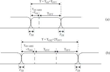
To make the spectrum decrease faster, windowing is applied to the OFDM
is included using the following function [4]:
WT(t) = sin2 ( π 2 (
0.5 + Tt
T R
))
, f or(−TT R2 < t < TT R2 )
1, f or(TT R2 ≤t ≤T − TT R2 )
sin2 (
π
2 (
0.5− Tt−T
T R
))
, f or(T − TT R2 ≤t < T +TT R2 )
(2.3)
considering thatTT R is the transition time between two consecutive periods of FFT,
as it can be seen in Figure 2.3.
Figure 2.3: OFDM frame with cyclic extension and windowing
Figure 2.3 also illustrates the possibility of extending the windowing function
over more than one period, TF F T , and additionally shows smoothed transitions by
application of a windowing function, as exemplified in Equation (2.3). In particular,
definition of the preamble.
Several other conventional windows were simulated including raised cosine,
Hann, Hamming, Blackman and Kaiser. The best performance was obtained for the
Blackman window, considering the resulting stopband attenuation and the transition
bandwidth.
2.2
Cyclostationary Signal Analysis
Signal cyclostationarity has been used as a statistical tool in many different
appli-cations, including spectrum sensing, blind equalization, parameter estimation and
modulation recognition [5] - [7]. Communication signals in general exhibit
cyclosta-tionarity associated with the symbol period, carrier frequency, chip rate and a
combi-nation of these factors [8]. Before discussing the cyclostationarity in OFDM signals,
the fundamental concepts of cyclostationary processes will be first introduced.
A cyclostationary signal is a signal having statistical properties which vary
cyclically with time. Define the mean and time-varying autocorrelation function
(ACF) of a stochastic process x(t) ( e.g., an OFDM communication signal) as
µx(t) = E{x(t)} (2.4)
and
Rx(t1, t2) =E{x(t1)x∗(t2)} (2.5)
HereE{·}is the standard expectation operator and ∗ is the conjugation of the
x(t) is wide-sense cyclostationary if its mean and time-varying ACF are periodic
in time [9], [10] with a period T. Namely, for any given integerm,
µx(t) =µx(t+mT) (2.6)
and
Rx(t1, t2) = Rx(t1 +mT, t2+mT) (2.7)
Without loss of generality, define t1 =t+τ /2 and t2 =t−τ /2. An alternate
definition of the time-varying ACF for a cyclostationary process is
Rx(t, τ) = E{x(t+τ /2)x∗(t−τ /2)} (2.8)
Rx(t, τ) is referred to as the symmetric form of the time-varying ACF since
it considers two points in time separated by τ and centred at t. Due to the
clear-ness and simplicity, (2.8) will be used in the following for further explanation about
cyclostationarity.
Analogous to (2.7), wide-sense cyclostationarity in (2.8) can be expressed as
Rx(t, τ) =Rx(t+mT, τ) (2.9)
For any cyclostationary process x(t) that satisfies (2.9), the time-varying ACF
can be expressed as a Fourier series over the corresponding period T
Rx(t, τ) =
∑
α
where the Fourier series coefficients in (2.10) are given as
Rxα(α, τ) = 1 T
T /2 ∫
−T /2
Rx(t, τ)e−j2παtdt (2.11)
Rxα(α, τ) is referred to as the CCF whereαis the cyclic frequency (CF). If a process is
wide-sense stationary, the CCF is identically zero for allα other thanα= 0. In other
words, for a stationary process, Rx(t, τ) =Rx0(t, τ) and Rx(t, τ) can be shortened as
Rx(τ) because it is no longer dependent upon t.
The CCF can also be obtained by extending the period of integration in (2.11)
to infinite as follows
Rαx(α, τ) = lim
T→∞
1 T
T /2 ∫
−T /2
Rx(t, τ)e−j2παtdt (2.12)
This expression together with the definition ofRx(t, τ) given in (2.8), provide a
method for estimating the CCF from observed waveforms. Suppose that samples from
the processx(t) are observed during any observation intervalT, and this observation
interval is symmetric with respect to the time origin. An estimate for Rαx(τ) is then
given by
ˆ
Rx(α, τ) =
1 T
T /2 ∫
−T /2
where I is the indicator function defined as
T =
1, |t ≤T /2
0, elsewhere,
(2.14)
Moreover, define the Fourier transform of the CCF with respect to τ as the
cyclic spectrum (CS)
Sx(α, f) =
∞ ∫
−∞
Rαxe−j2πf τdτ (2.15)
When α = 0, CS is equal to the power spectrum (or spectral density) defined
in the conventional manner [10]. For any wide sense stationary process, the CS is
identically zero for allα other thanα= 0. This follows directly from the equivalence
of Rτα=0 toR(τ) for such a process.
2.3
Blind Parameter Estimation
Various blind OFDM system parameters estimation schemes have been studied in
recent years for both signal identification and signal behaviour analysis. The existing
techniques can be generalized into two categories: with or without sampling frequency
at the transmitter as prior information. The first category has been widely explored
[11], which focused on the synchronization and other parameters. Furthermore, [12]
and [13] present more complete OFDM system parameters extraction which employs
the correlation method to explore the system parameters of OFDM systems. However,
this category of techniques cannot apply to the considered public security problem
Therefore, for signal detection purpose, blind parameter estimation without
any prior information is investigated in the PSTP milestone 3. Among those
sys-tem parameters, the decisive one is the sampling frequency at the transmitter with
which the signal can be downsampled from carrier frequency and the subsequent
processing is available. There are two primary approaches under current research:
cyclostationarity-based and nonparametric spectrum-based estimation. In details,
cy-clostationary theory, developed for years in various signal processing areas, was first
introduced into OFDM system analysis in [11] and based on Dandawat and
Gian-nakis’ work [15], the key step to estimate sampling frequency through cyclostationary
properties is to examine the cyclo-period of oversampled OFDM signal at the receiver.
In literature, Martin and Kedem [16] detected this period through the periodogram
associated with the sequence having the similar period to the least common
multi-ple periods of the original cyclostationary signal; Hurd and Gerr [17] obtained the
cyclo-period from the bispectrum, which was estimated using the two-dimensional
pe-riodogram; Dandawat and Giannakis [15] aimed at the detection of cyclo-stationarity
under a broader context, almost cyclo-stationary signals, through a statisticalχ2 test
based on the cyclic covariance and the cyclic spectrum. In [18],
cyclostationarity-based sampling frequency estimation through Dandawat and Giannakis approach is
presented. However, the above cyclostationarity-based methods failed to fulfill the
demands of military communications since computational complexity leads to overly
long processing and detection times. As a result, a low complexity OFDM receiver is
proposed in the following parts where system parameters, modulation schemes and
channel state information (CSI) are jointly estimated based on the cyclic spectrum.
Specifically, conventional cyclostationary analysis is replaced by a new scheme where
only the samples around specific feature points are computed instead of calculating
negligible performance degradation. Based on the cyclic spectrum features, key
sys-tem parameters (sampling frequency, cyclic prefix ratio, number of subcarriers and
frequency offset as well as timing offset) can be successfully obtained which provide
the essential information required for signal identification. Additionally, blind channel
estimation is also included such that the signal can be completely demodulated.
On the other hand, a non-parametric spectrum method for blind parameter
estimation which is based on spectrum information and autocorrelation is an
alterna-tive and complete investigation is provided in [19]. Unfortunately, the method does
not work well for upsampling method with raised cosine filter at transmitter which
is closer to the practical implementation. We propose a blind estimation method to
obtain the key parameters of OFDM system, based on which an iterative channel
estimation scheme is proposed to provide CSI as well with enhanced accuracy for
po-tential resource optimization in networks. We establish a novel two-step estimation
scheme where accurate results are achieved based on the first step coarse
estima-tion. Other system parameters as mentioned above are subsequently estimated as
the input of the channel estimator. Then an iterative channel identification scheme is
proposed to improve the performance of traditional pilot-based methods in the hostile
environments.
Blind signal interception is a fundamental step of signal intelligence for
mili-tary applications. However, there are substantial technical challenges to overcome in
sensing and identifying various wireless signals due to the existence of many
differ-ent transmission technologies and standards. The key requiremdiffer-ents to achieve blind
signal interception include detecting the existence of a signal and identification of its
parameters and features. With the proper system parameter identification results,
2.4
Introduction of the Proposed Approach
Orthogonal Frequency Division Multiplexing (OFDM) has been widely employed in
many civilian and military broadband communication systems due to its high
spec-tral efficiency and robustness to multi-path interference. Various blind OFDM system
parameter estimation schemes have been studied recently for signal identification [18]
-[21]. Among the existing techniques, cyclostationary estimation is the most
com-monly used due to its reasonable estimation accuracy for various types of air interface
identification. In general, cyclostationarity is an important feature of wireless
com-munication signals which can be used to determine the existence and classification of
a signal [8],[22]. Additionally, cyclostationary analysis has been extensively examined
as a technique for achieving a wide range of analysis in OFDM systems including
sig-nal detection [23], frequency and timing synchronization [24] and channel estimation
[25]. Therefore, improving the reliability of cyclostationarity detection will provide
more accurate system information for further processing of an intercepted signal.
Most signal detection methods are not suitable to fulfill the demands of military
communications since computationally complex receiver design leads to overly long
processing and detection times [18] -[20]. In addition, traditional methods require the
exploration of a wide range of cyclic frequencies and require a long observation time
in order to obtain reliable analysis.
Since the oversampling ratio at the receiver can be arbitrary, it is hard to achieve
high estimation accuracy for non-integer oversampling ratios. As a result, a low
complexity approach is required to overcome the above challenges. The Zoom
Fast-Fourier Transform based method in [21] was proposed to provide a
computationally-efficient estimation with high accuracy, however, the observation time required is still
frequency instability.
In this chapter, we present an iterative scheme for blind parameter estimation
of OFDM interception receiver design, which is based on cyclostationary feature
de-tection. The method avoids the exploration of a wide range of cyclic frequencies by
first narrowing the analysis to a region containing the feature of interest and
per-forming high resolution exploration in that region to accurately detect the feature.
Based on the detected features, system parameter estimation (sampling frequency,
number of subcarriers and Cyclic Prefix (CP) duration) can be successfully obtained
which provide the essential information for blind identification. Since the
compu-tational complexity of the proposed system is significantly reduced with negligible
performance degradation, the usefulness of the entire system is thus increased. The
proposed receiver in this chapter is capable of providing reliable signal identification
for military signal intelligence applications.
2.5
System Model
Due to the time-varying nature of the wireless channel, it is difficult, at times, to
determine the presence or existence of a wireless signal. In this case, the periodicity
of signal features such as the mean, correlation or spectral descriptors can be used
to determine signal existence and is known as cyclostationary analysis [25]. A signal
is called second-order cyclostationary if its time-varying auto-correlation function
Rx(t, τ)
Rx(t, τ) =E{x(t)x(t+τ)} (2.16)
is periodic in t for a given delay τ. An OFDM signal possesses a periodic
cyclostationary[24].
2.5.1
Oversampled OFDM System Model
Consider an OFDM system with Ns transmission subcarriers. We make the
assump-tion that due to the inserassump-tion of the cyclic prefix, there is no inter-symbol interference.
Without loss of generality, we focus on one OFDM symbol with duration Ts. The
transmitted OFDM signal in baseband over [0, Ts) can be represented as
s(t) = √1 Ns
N∑s−1
k=0
dkexp(j2π k Ts
t)u(t) (2.17)
where u(t) denotes a raised cosine filter defined in [0, Ts) and dn represents a data
symbol with unit average power on the nth subcarrier. Specifically, letting
d,[d0, d1, ..., dNs−1]
T (2.18)
the data symbols on Ns subcarriers satisfy
E[ddH] = INs (2.19)
where INs is an identity matrix of size Ns byNs.
Suppose that h(t) is an unknown frequency selective multipath channel. The
received time-domain signal can be written as
x(t) = ∑
m
h(m)s(t−mTs) +w(t) (2.20)
σw2. Assuming that the sampling period at the receiver side is Tb with Tb < Ts, the
oversampling factor q is defined as q = Ts/Tb and the corresponding oversampled
OFDM signal can be consequently denoted by
x(n) =∑
m
h(m)s(n−qm) +w(n) (2.21)
2.5.2
Cyclostationary Analysis in Oversampled OFDM
Signals
Iftandτ in (2.16) are replaced witht+τ /2 andt−τ /2, the autocorrelation function
can be expressed as
Rx(t, τ) =E{x(t+τ /2)x(t−τ /2)} (2.22)
Therefore, the periodicities can be examined using the cyclic autocorrelation function
(CAF) [8],
Rαx(τ) = lim
T→∞
1 T
T /2 ∫
−T /2
Rx(t, τ)e−j2παtdt (2.23)
for cyclic frequency α and observation length T.
Cyclostationary features can be detected from specific correlation patterns which
occur in the spectrum of the signal. These patterns can be measured by the
normal-ized correlation between two spectral components ofx(t) at frequenciesf+ ∆f /2 and
f−∆f /2, where ∆f is the spectral resolution size. The spectral correlation function
(SCF) is introduced to calculate the cyclic spectrum, which is given by [8]
Sxα(f) = lim
∆f→0Tlim→∞
1 T·
1 ∆f·
f+∆∫ f /2
f−∆f /2
XT(t, v+α 2)X
∗
T(t, v− α
where
XT(t, v) =
t+∫T /2
t−T /2
x(u)e−j2πvudu (2.25)
represents the time-variant Fourier transform of x(t). Together the CAF and SCF
provide a comprehensive means of examining the cyclostationary features of a signal.
Gardner [8] proved that in order to obtain satisfactory estimation information, the
time-spectral resolution product must exceed unity, i.e.,
T∆f ≫1 (2.26)
This implies that a lengthy observation time with a high spectral resolution ∆f is
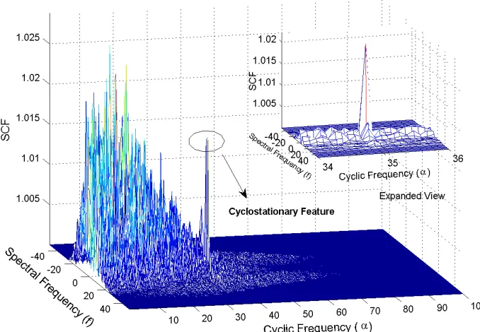
required to resolve the individual features of the SCF. The SCF for a baseband OFDM
signal is shown in Figure 2.4.
Since no prior information is available for a blind OFDM interception receiver,
a captured signal must be oversampled for successful reception as well as for correct
estimation. Identification of cyclostationary features using an arbitrary oversampling
ratio is a challenge for blind OFDM interception receiver design.
Figure 2.5 shows the SCF of the baseband OFDM signal using an oversampling
ratio ofq = 2.85. We can see that, due to the oversampling ratio used, the SCF
infor-mation has been shifted towards the zero spectral frequency axis with the significant
peak located at the edge of the signal of interest.
Ideal SCF estimation requires the traversal of the entire cyclic and spectral
frequency domains as well as a lengthy observation time with high spectral resolution,
resulting in high computational complexity and increased processing delay. In the
following sections, an iterative scheme is introduced to determine the cyclostationary
Figure 2.4: SCF estimate for a baseband OFDM signal.
is found, using simulations, that the proposed method reduces the computational
load drastically. Blind parameter estimation is realized based on this low-complexity
cyclostationary feature analysis.
2.6
Iterative Cyclostationary Analysis with
Arbitrary Oversampling Ratio
After the detection of an incoming signal, the OFDM interception receiver must
identify the desired cyclostationary feature represented as a peak shown in Figure 2.5.
Suppose that the index of the peak of the desired cyclostationary feature along the
cyclic frequency axis is α using a spectral resolution size ∆f. The length of the
Figure 2.5: SCF for oversampling ratio q = 2.85.
oversampling ratioqhas been estimated, further parameter estimation can be realized
based on thisq. In order to maintain low computational complexity, iterative analysis
is used to increase the oversampling ratio estimation accuracy by first performing low,
and then high resolution estimation.
For an oversampled OFDM signal, the desired cyclostationary feature is located
at the edge of the signal of interest in SCF analysis. One can reduce the computational
load by applying an iterative method with increasing observation time as well as
decreasing spectral resolution size to only a limited search range of the cyclic frequency
axis, which includes the desired peak index.
Low spectral resolution gives coarse SCF information which makes it impossible
to detect the cyclostationary feature. However, the edge of signal of interest is still
resolution is to identify the relative position of the signal of interest while maintaining
a low computational load.
Assume that the tentative short observation time of the SCF for signal detection
isTl and the low spectral resolution is ∆fl, then the time-spectral resolution product
is small and the corresponding Sxα(f) is achieved based on (2.24). Therefore, if the
existence of an incoming signal is declared, the analysis is then performed on the
entire cyclic spectrum using coarse analysis to obtain the spectrum information. We
can then detect the edge of the signal of interest and we can assume that this edge
is located between i and j along the cyclic frequency axis where i < j ∈(1,1/∆fl).
Two tentative factors are thus decided as
q1 = 1
j∆fl (2.27)
q2 = 1 i∆fl
Using q1 and q2 we can broadly define the region of interest that contains the
exact oversampling ratio q, i.e., q1 < q < q2. In order to accurately determine q,
we must increase the time-spectral resolution in the region of interest defined by q1
and q2. Therefore, we can explore a subset of the entire cyclic spectrum instead of
exploring the entire cyclic spectrum itself. In this region we now perform a high
time-spectral resolution analysis with high estimation accuracy. Let us denote the
product of ∆fh and Th to be the high time-spectral resolution candidate. The range
of interest is now limited to α1 and α2, given as
α1 = 1
∆fhq2 (2.28)
α2 = 1
We can iteratively improve the estimation accuracy with each iteration
increas-ing in time-spectral resolution within the selected range. Since an arbitrary
over-sampling ratio scenario is considered, both integer and rational overover-sampling ratios
are possible. Using the iterative approach allows for the efficient estimation of both
integer and rational oversampling ratios which can then be used to detect the desired
cyclostationary feature accurately.
If the estimated oversampling ratio at j−1, j and j + 1 steps areq(j−1), q(j)
and q(j+1), the final estimation result is achieved if the following conditions are met
|q(j+1)−q(j)|<|q(j)−q(j−1)|< γ (2.29)
where γ is the level of acceptance. Suppose that ∆ ˆf is the spectral resolution size
at this step and ˆα is the desired peak index representing the cyclostationary feature.
The estimated oversampling ratio ˆq is identified as
ˆ
q= 1
ˆ
α∆ ˆf (2.30)
With this oversampling ratio, the sampling frequency of a transmitted OFDM
signal can be determined and the corresponding OFDM symbol length is calculated
as well. Therefore, the transmitted OFDM signal is correctly detected by the
2.7
Parameter Estimation Based on Detected
Cyclostationary Feature
After correctly sampling the received continuous signal, the proposed OFDM
intercep-tion receiver must identify the primary system parameters of the intercepted signal.
The parameters defined here are the number of subcarriers as well as the length of
the cyclic prefix (CP).
For an OFDM symbol withNs subcarriers, the estimated autocorrelation
func-tion ˆRx(n, τ) of the oversampled signal can be written as
ˆ
Rx(n, τ) =
1 P
P∑−1
n=0
x(n)x∗(n−τ), τ ∈[0,1, ..., P −1] (2.31)
whereP is the length of oversampled incoming signal. The absolute value of ˆRx(n, τ)
is considered and is given as
|Rˆx(τ)|= ∑P
n=0|h(n)|2 +σw2, τ = 0
∑P
n=0|h(n)|2
Ng
Nf +σ2w, τ =Nb,
(2.32)
whereh(n) stands for the frequency selective channel impulse responses andσ2w
repre-sents the variance of the AWGN,Ng is the CP length,Nb is the OFDM symbol length
of the oversampled signal withNb =qNsandNf is the length of the OFDM subframe
including CP. |Rˆx(τ)| will have the most significant peak when τ = Nb. Therefore,
through peak detection, the estimated number of subcarriers can be achieved by
ˆ Ns =
Nb ˆ
Estimation of the CP length has been discussed in many papers previously ([19],
[21], and [41]). However, some implementations use exhaustive autocorrelation
anal-ysis [41], some require prior information for accurate results [19] and some techniques
are only successful for certain pre-defined CP lengths [21] which are not available
for blind interception receiver design. Therefore, in this section, a new approach is
developed which utilizes the cyclic autocorrelation information.
Assume that Nf =Ng +Ns is the length of OFDM subframe. The estimated
cyclic autocorrelation is given by
Rxk(τ) = 1 P
P∑−1
n=0
Rx(n, τ)e−j 2π
P kn, (k, τ)∈[0,1, ..., P −1] (2.34)
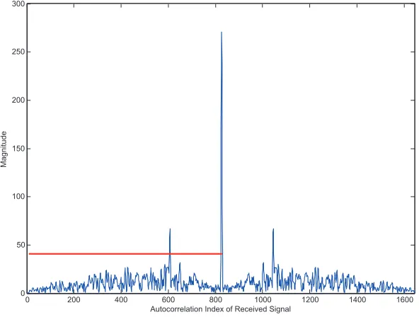
where P is the length of the oversampled signal. Using the estimated number of
subcarriers Ns, we can obtain the cyclic autocorrelation with delay τ = Ns. The
cyclic prefix length, Ng, can be determined by using peak detection onRkxatτ =Ns.
kopt represents the first peak with the smallest index above the threshold from the
0 200 400 600 800 1000 1200 1400 1600
0 50 100 150 200 250 300
Autocorrelation Index of Received Signal
Ma
g
n
it
u
d
e
cyclic autocorrelation. Therefore, Nf can be identified as
Nf = 2P kopt
(2.35)
and the CP length Ng is determined as Ng =Nf −Ns.
2.8
Enhanced Channel Estimation with System
Parameters Estimation
After blind parameter estimation for received OFDM signal, further channel
identi-fication can be performed based on the necessary parameters. Here we assume the
baseband received signal after downsampling is denoted by x(n).
2.8.1
Pilot Block Detection
In traditional communication system, the power of pilot block is higher than data
blocks which is shown in Figure 2.7. Therefore, the pilot block can be detected using
the energy detector,
E =∑
n
|x(n)|2. (2.36)
which means if the energy of a certain block is higher than the average of other, it
can be determined as a pilot block.
2.8.2
Iterative Channel Estimation
After detecting the position of pilot block, an enhanced iterative channel estimation
scheme is proposed in this section to improve the performance of traditional
Figure 2.7: Different power levels allocated to the pilot block and data block
over a number of OFDM symbols in common wireless environment. Therefore, the
principle of the enhanced channel estimation is that we utilize the initial channel
estimate provided by the pilot block to obtain tentative demodulation results of the
subsequent OFDM symbols. The demodulated OFDM symbols are combined with
the original multiplexed pilot block to enhance the power of the pilot. We summarize
the algorithm as follows:
1. Obtain initial channel estimation by using the block-type block through Least
Square (LS) estimator:
ˆ Hl = Xl
Pl, l = 0,1,· · ·, Ns−1, (2.37)
subcar-rier. Pl and Xl denote the pilot symbol and corresponding received sample on
the lth subcarrier.
2. Equalize the subsequent OFDM symbols using the current channel estimate,
˜
dn,l =Xn,l/Hˆl, n= 1,2,· · · , B, (2.38)
whereB represents the number of OFDM blocks needed for channel estimation
accuracy enhancement.
3. Make data decisions on the equalized OFDM symbols and denote them as ˆdn,l.
Then update the channel estimation as follows,
ˆ
Hl = 1
1 +B Yl
Pl + B
∑
n=1
Xn,l ˆ dn,l
. (2.39)
4. Repeat Steps 2) and 3) to simultaneously improve the accuracy of channel
esti-mation and data detection until the estiesti-mation results converge or a predefined
number of iterations is achieved.
2.9
Simulation Results and Discussions
This section provides simulation results for the statistical tests of the proposed system.
Monte Carlo simulations are conducted to examine the performance of the above
es-timation approaches under different scenarios. The parameters of the OFDM system
used in the simulation are: number of subcarriers Ns = 200, length of cyclic prefix
Ng = 45 and roll-off factor of raised cosine filter at transmitter is 0.5. The multipath
10 complex Gaussian distributed taps. For any variable X, the mean square error
(MSE) is expressed as MSE =|X′ −X|2, where X′ is the estimated value and X is
the original.
MSE =|X′−X|2 (2.40)
where X′ is the estimated value andX is the original one.
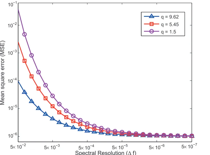
The MSE of an arbitrary oversampling ratio estimation is exhibited in Figure 2.8
under different frequency resolutions. The Signal-to-Noise Ratio (SNR) used is 10 dB.
From the figure it is obvious that the spectral resolution is an important factor and
that a higher resolution leads to improved accuracy. Based on the Monte Carlo
simulation, 0.1 and 5×10⁻⁶ are chosen as the optimal low spectral resolution and
high spectral resolution, respectively. Under such selection, the desired estimation
accuracy is realized and low computational complexity is maintained as well.
The simulation results demonstrate the estimation ability of the proposed
ap-proach on arbitrary oversampling ratios. Compared with the numerical results of the
entire spectrum SCF estimation [21], [40] and [41] the estimation accuracy of the
proposed approach is satisfying. Since a higher oversampling ratio provides more
sig-nal information, better estimation accuracy is achieved according to the simulation
results.
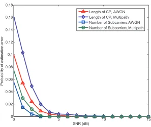
Figure 2.9 illustrates the performance of the introduced approaches for the
esti-mation of the number of subcarriers and the CP length. Instead of using recognizable
and distinctive features of an OFDM signal, arbitrary parameters are employed to
test the validity of the proposed receiver design. The oversampling ratio used in the
simulation isq= 5.45. The performance is analyzed using both AWGN and multipath