Comparison between Microstrip Rectangular
and Circular Patch Antenna for 5G
Application
Ribhu Abhusan Panda1, Ranajit Sahana2, Eswar Prasad Panda2
Assistant Professor, Department of ECE, Gandhi Institute of Engineering and Technology, Gunupur, Orissa, India1
B.Tech, Department of ECE, Gandhi Institute of Engineering and Technology, Gunupur, Orissa, India 2
ABSTRACT : This paper demonstrates a comparative study of Rectangular and Circular Patch Antenna. The centre
frequency 28Ghz is chosen as the resonating frequency which is perfect for 5G application. The antenna is designed on a FR-4 Epoxy substrate having dielectric constant of 4.4.The height of the substrate is 1.6mm above the ground. HFSS 12 is used as a designing software and for simulation process. The antenna VSWR, Gain, s-Parameter of the proposed both Rectangular and Circular Patch antenna are analysed from the simulation results of HFSS. Hence, it is capable for 5G application in fields of mobile communication.
KEYWORDS: HFSS,5G,MICROSTRIP ,RECTANGULAR,CIRCULAR.
I. INTRODUCTION
ISSN (Print) : 2320 – 3765 ISSN (Online): 2278 – 8875
I
nternational
J
ournal of
A
dvanced
R
esearch in
E
lectrical,
E
lectronics and
I
nstrumentation
E
ngineering
(An UGC Approved Journal)
Website: www.ijareeie.com
Vol. 6, Issue 9, September 2017
II. THE DESIGNED ANTENNA LAYOUT
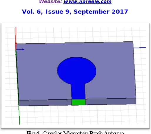
Fig 4- Circular Microstrip Patch Antenna
In this paper, we have designed a Rectangular and Circular Microstrip patch antenna using conducting material. Substrate is designed using a box having material FR4 EPOXY with dielectric coefficient( ) 4.4[7-10] . The height(h) of the substrate is 1.6mm with respect to z-axis. The ground plane is made at the bottom of the patch having same length and breath and assigned boundary “Perfect E1”. The outer box is designed using air material and assigned with radiation “rad1”. U shaped patch and feed line are united and assigned boundary “Perfect E2”. Slot is assigned with excitation and than connecting it with the feed line on the “YZ axis”.
III. MATHEMATICAL FORMULAE
Microstrip patch antennas have many method of simulation.
The rectangular patch is far the most widely used configuration. It is very easy to analysis using the cavity and
transmission line model. Since the dimension of the rectangular patch and substrate is given by[1-5, 9,10-12]
1. W =
ε
The width of the patch is denoted as W ; where Vo is speed of light that is 3×10⁸ , fr is the resonant frequency that is
28Ghz for 5G application and the dielectric constant of substrate is “FR4-Eproxy”( ) is 4.4 The effective dielectric constant (ε ) given by ;
2. ε = ε +ε 1 + 12
where h is the height of the substrate which is 1.6 from ground level;
3. ∆ = 0.412ℎ (ε . ) . (ε . ) .
4. =
√ √
−2∆
L= normalized extension in length L= length of the patch
5. = 1 + + 1.7726
6. = . ×
√
ISSN (Print) : 2320 – 3765 ISSN (Online): 2278 – 8875
I
nternational
J
ournal of
A
dvanced
R
esearch in
E
lectrical,
E
lectronics and
I
nstrumentation
E
ngineering
(An UGC Approved Journal)
Website: www.ijareeie.com
Vol. 6, Issue 9, September 2017
IV. STIMULATION RESULTS
Fig-5 S-parameter of Rectangular patch antenna
Fig-6 S-parameter of Circular patch antenna
In the above fig-5 the resonant frequency is obtained in Rectangular patch antenna is 28.15GHz and in fig-6 Circular path antenna the resonant frequency obtained is 31.37GHz
Fig-8 VSWR of Circular Microstrip Patch Antenna
VSWR(Voltage Standing Wave Ratio), is a measure of how efficiently radio-frequency power is transmitted from a power source, through a transmission line, into a load. VSWR measures these voltage variances it is the ratio of the highest voltage anywhere along the transmission line to the lowest.
Fig-9 Radiation pattern of Rectangular Microstrip path antenna
ISSN (Print) : 2320 – 3765 ISSN (Online): 2278 – 8875
I
nternational
J
ournal of
A
dvanced
R
esearch in
E
lectrical,
E
lectronics and
I
nstrumentation
E
ngineering
(An UGC Approved Journal)
Website: www.ijareeie.com
Vol. 6, Issue 9, September 2017
Figure-4 Comparison between S-parameter of Rectangular (green) and Circular (red) Microstrip patch antenna
In fig- 4 there is comparison between the S-Parameter in rectangular and circular patch antenna . The green colour graph shows the curve of rectangular patch antenna and the red colour graph shows the curve of circular patch antenna. The Maximum Resonant frequency, VSWR and Gain for Rectangular patch antenna is 28.5GHz and -3.0 dB and for circular patch antenna is 31.37GHz.
Desired Resonant frequency is 28.15GHz for VSWR and -2.0 dB for Gain which is suitable for 5G application.
TABLE-I (COMPARISON TABLE)
Parameters Rectangular Patch antenna Circular Patch Antenna
Resonant Frequency
28.05 GHz 31.37 GHz
VSWR 28.5 GHz 31.5 GHz
Gain -3 dB -2 dB
(Comparison between Rectangular patch and Circular Patch)
V. CONCLUSION
The design of patch antenna’s has brought new challenges to designers. This research was aimed to design 5g antenna using rectangular patch antenna .In this paper the comparison between the Rectangular Patch Antenna and circular patch antenna has been done for 5G application. The results have been found out to be in the desired range of frequency 28 GHz which is suitable for 5g applications . In this course of the project, we concluded that the Rectangular Patch antenna gives the better result than the circular patch antenna.
ACKNOWLEDGMENT
REFERENCES
[1] Ribhu Abhusan Panda, “Perturbed Elliptical Patch Antenna Design for 50 GHz Application”, Springer,ISBN-978-81-322-2726-7,pp- 507-518. [2]Ribhu Abhusan Panda, Eswar Prasad Panda, Ranajit Sahana, Nidhi Kumari Singh “Modified Rectangular patch antenna for 5g application at 28 Ghz”, IOSR Journal of Electronics and Communication Engineering (IOSR-JECE), vol. 12, no. 4, 2017, pp. 06–10 .
[3] Ribhu Abhusan Panda and Debasis Mishra, “Log-Periodic Waning Crescent Patch Antenna For X-Band Applications”, International Journal of Recent Scientific Research Vol. 7, Issue, 3, pp. 9483-9487, March, 2016.
[4] Ribhu Abhusan Panda, Harihar Panda, Debasis Mishra, “Log Periodic Implementation of Biconvex Patch Antenna”, International Journal of Emerging Research in Management & Technology ISSN: 2278-9359 (Volume-5, Issue-3).
[5] Veerendra Singh Jadaun, Pavan Kumar Sharma, Ashish Duvey, “Design A Microstrip Patch Antenna of Single Band For 1.8GHz”, international conference e-manthan 2012, 6-7 april 2012, Jhansi. .
[6] Pavan Kumar Sharma, Hemant Kumar Gupta, Veerendra Singh Jadaun, Ritesh Kumar Tambulkar,” Design of Sierpinski Microstrip Patch Antenna for Wireless Power Transmission for ISM Band (2.45GHz)”, international conference e-manthan 2012, 6-7 April 2012, Jhansi.
[7] Wikipedia, “5G”.
[8]. T.F.Lai, Wan Nor Liza Mahadi, Norhayati Soin, “Circular Patch Microstrip Array Antenna for KU-band” World Academy of Science, Engineering and Technology 48 2008.
[9] C.A. Balanis, Antenna Theory, 2nd Ed., John wily & sons, inc., New York.1982.
[10] Tanish Narang; Shubhangi jain; “Microstrip Patch Antenna- A Historical Perspective of the Development”, Conference on Advance in Communication and Control Systems2013 (CAC2S 2013).