Analysis of Power Quality Enhancement in MFGCI
with Fuzzy based Active Power Control
Chilakala Nagarjun M-Tech Student Scholar
Department of Electrical & Electronics Engineering, KITS College of Engineering ,
Khammam, Telangana, India.
M. Gowri Shankar Associate Professor
Department of Electrical & Electronics Engineering, KITS College of Engineering ,
Khammam,Telangana, India
Abstract: Recent scenario in the distribution system is harmonics created by Nonlinear load and unbalance current. It affects not only the working of adjacent loads but also shorten the life of power equipment by creating excessive losses. In this paper, a fuzzy controlled shunt active power filter is described to maintain the (Total Harmonic Distortion) THD within the allowable limits defined by IEEE Std. 519-1992 and to reduce reactive power and improve power factor. This Filter draws the opposite harmonics containing current from the load so that source current remain sinusoidal and undistorted. Fuzzy logic controller is used to control the shunt active power filter and the performance of the shunt active filter control strategies has been evaluated in terms of harmonic mitigation. Three-phase reference current waveforms generated by proposed scheme are tracked by the three-phase voltage source converter in a hysteresis band control scheme. A fully functional MATLAB based Simulink model of Shunt Active Power Filter for different types of load (nonlinear, unbalance, both) has been designed based on `Instantaneous Power Theory' or `p-q Theory'. The results of simulation comply with all the features described by the theory, justifying employment of Shunt Active Power Filter (SAPF) with fuzzy controller improves power quality compared to conventional Proportional Integral(PI) controller.
.
1 INTRODUCTION
In recent years Distributed Generation (DG) based on Renewable Energy Sources (RES) has undergone tremendous development globally. Due to the increasing energy demand, reducing fossil fuels and clean energy concepts more and more DG units are connected to the grid at the distribution level [1]. Microgrid which integrates RESs, energy storage devices and local loads are a solution to the present day energy crisis [2].Power quality is a major issue in a conventional distribution system in the presence of increased usage of nonlinear loads and power electronic based equipments. Poor power quality is a big challenge for the stable, effective and economic operation of an inverter dominated microgrid [1, 3, 4, and 8]. In the near future electricity will be a commodity marketed by judging its quality in a competitive environment [8]. A number of active power filtering techniques have been developed to mitigate the traditional distribution system harmonic issues [6]. The basic structure of an active
filter is similar to that of a DG inverter and the primary function of these grid interfacing inverters is to inject active power to the grid. The DG inverter may not operate at its full capacity at all the time due to the stochastic nature of the renewable energy sources like solar and wind [7]. If controlled properly the unused capacity of DG inverter scan be effectively used for providing ancillary services like harmonic, reactive power compensation and unbalance mitigation of the power distribution system [2, 7, 8, and 9]. Such an inverter can be called as a multifunctional grid connected inverter (MFGCI). With the recent developments in microgrid technology power quality enhancement using flexible control of MFGCI is an interesting research topic [10]. Use of MFGCI eliminates the necessity of additional compensating devices and results in a cost effective system [7-9]. Voltage Source inverters are used as the interfacing converters in most of the DG systems. Normally these inverters operate in current controlled mode (CCM) during grid connected operation due to its superior harmonic compensation capability when compared to the voltage controlled mode (VCM). Various control strategies and techniques for enhanced power quality in a grid connected system have been reported recently [8-[4]. During harmonic compensation of the nonlinear load current, the fundamental DG current supplied by the interfacing inverter has to be calculated based on the active and reactive power reference.
A control technique with power quality improvement features for the integration of DG systems to the grid is discussed in [12]. In this strategy generation of fundamental DG current component assumes a stiff voltage source at the grid side and does not consider non ideal supply conditions. An open loop power control strategy for optimal power quality compensation in Microgrid using multifunctional grid connected inverters is proposed in [13].An electrical distribution system is subjected to power fluctuations and uncertainties which causes the voltage at the point of common coupling (PCC) to be unbalanced.
closed loop power control strategy is necessary for accurate power tracking in the case of distorted voltages at the PCC. In [14], a closed loop power control strategy for single phase inverters with active harmonic filtering in stationary frame is proposed for harmonic compensation. The objective of this paper is to develop a control strategy for harmonic current filtering in a three phase grid connected DG system without using extra compensating device. The proposed closed loop control is able to track the active power reference and improve the power quality in the presence of unbalanced and distorted supply voltages. The effectiveness of the control scheme is validated by elaborate simulation studies for different operating modes of the DG inverter under ideal and non-ideal supply conditions.
II SYSTEM DESCRIPTION
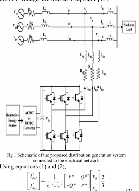
A schematic representation of the proposed system is given in Fig 1 and represents the grid resistance and inductance up to the point of common coupling; and represents the equivalent resistance and inductance of the inverter filter, coupling transformer and connecting cables; represents the smoothing inductance inserted in series with the load to reduce the spikes in the grid current due to switching transients;
, , represents the voltages at the PCC and , , represents the load currents.
III REFERENCE CURRENT GENERATION PRINCIPLE
The control technique employed is based on the analysis of load voltage, load current and inverter currents in the dq synchronous rotating frame. Independent control of active and reactive power can be achieved with more effectiveness in dq frame. The instantaneous angle of the voltage at PCC is obtained by using a phase locked loop (PLL).
a) Calculation of d-axis and q-axis reference currents to supply load active and reactive power:
The active and reactive power injected from the DG link to the grid at the fundamental frequency is
(1)
(2)
Where , and, and are the dq- components of DG invertercurrent at fundamental frequency to manage the active powerand reactive power exchange between the grid and RES. and are the the PCC voltages in dq frame.The currents at fundamental frequency required to deliver the active and reactive power from the RES has to be supplied by the DG inverter. The corresponding reference currents at fundamental frequency are∗ and ∗ , which can be calculated
using the open loop and the proposed closed loop power control strategy as explained below,
B) Open Loop Power Control:
In a practical case, the PCC voltages may contain ripple due to the unexpected power fluctuations and excessive use of harmonic polluted loads connected to the system. Hence to generate the fundamental current components, the PCC voltages are filtered in dq frame [13].
Fig 1 Schematic of the proposed distribution generation system connected to the electrical network
Using equations (1) and (2),
(3) Where and are the voltages after passing through a low pass filter. P * and Q*are the active and reactive power references.
c) Proposed Closed Loop Power Control:
In the proposed closed loop control strategy, the calculated DG active and reactive power are filtered through a low pass filter and compared with the reference powers to get the error signal. The dq - components of inverter reference current at fundamental frequency can be generated by passing the error signal through a PI controller and can be expressed as
(4)
real and reactive power control errors, As per IEEE 1547 the inverters in a distributed generation system are not permitted to inject reactive power to the grid [5]. As such, the total q-axis reference current for the inverter is limited to meet only the reactive power demand of the load so that ∗ = O. Hence only active power control
is done in both open loop and closed loop control schemes. In rotating synchronous frame the quadrature component of load current i1q is perpendicular to the direct component of voltage ( ). Accordingly the q-axis reference current of the DO inverter can be expressed as
(6)
d) Calculation of Total D-Axis Reference Current: The d-axis component of the load current can be expressed as
(7) Where in∎ is the oscillating component of the load
currentand is the fundamental component of load current. In dq frame the fundamental frequency component of the load current appears as a dc component. The harmonic components of the load current can be obtained by using a high pass filter. But due to the excessive phase lag associated with the high pass filter, a second order low pass filter having a cut off frequency of 25 Hz is used to extract the harmonic component of the load current.
∎ Can be expressed as
(8)
(9)
The DO inverter has to supply the d-axis component of harmonic load current given by equation (8) and the d-axis component of current at fundamental frequency given by equation (3) or (4) depending upon the type of the power control scheme. Hence the total d-axis reference current for the DO inverter can be expressed as
(10) e) DC Link Voltage Control:
When the power from the RES is equal to zero, the inverter operates in shunt active filter mode. The DO inverter draws an active power component of current for maintaining the dc bus voltage constant and to meet the losses in the inverter. The DC link voltage error can be expressed as
(11)
The current can be obtained by passing the error through a PI controller and is given by
(12) Where kp and k; are the proportional and integral gain constants.
f) Hysteresis Current Control Scheme:
A Hysteresis band current controller is used to generate the switching pulses for the DO inverter. The reference currents generated in dq frame are transformed to natural ABC frame and compared with the inverter currents to generate the error signals.
If ∗ − > ℎ ,then upper switch is switched ON
and lower switch is switched OFF in the inverter leg of phase 'a'.
If ∗ − < ℎ then upper switch is switched OFF
andlower switch is switched ON in the inverter leg of phase 'a',
Where ℎ is the assigned hysteresis band? Using the same principle switching pulses for the other switches in phase 'b'&'c' are produced. The hysteresis band directly controls the amount of ripples in the current injected into the grid. The main advantages of hysteresis current controller are ease of implementation, extremely good dynamic response, outstanding robustness and independence of load parameter changes [17]. The switching frequency depends on the width of hysteresis band, the size of interfacing inductor Ldg to the grid and the DC voltage. As per [18], the relation between switching frequency and the filter inductance can be expressed as
(13) Where is the DC link voltage, ℎ is the hysteresis band and is the maximum switching frequency.
IV FUZZY LOGIC CONTROLLER
In recent years, the number and variety of applications of Fuzzy Logic (FL) have increased significantly. The applications range from consumer products such as cameras, camcorders, washing machines, and microwave ovens to industrial process control, medical instrumentation, decision-support systems, and portfolio selection. To understand why use of Fuzzy Logic has grown, it must be first understood as what is meant by Fuzzy Logic.
more narrow definition, Fuzzy logic differs both in concept and substance from traditional multivalve logical systems.
a) Fuzzy logic tool box:
The Fuzzy Logic Toolbox provides GUIs to perform classical fuzzy system development and pattern recognition. Toolbox used to develop and analyze fuzzy inference systems, develop adaptive neuro fuzzy inference systems, and perform fuzzy clustering. In addition, the toolbox provides a fuzzy controller block that which uses in Simulink to model and simulate a fuzzy logic control system. By using Simulink, C code can be generated which is used in embedded applications that include fuzzy logic.
b) Building a Fuzzy Inference System:
Fuzzy inference is a method that interprets the values in the input vector and, based on user defined rules, assigns values to the output vector. Using the GUI editors and viewers in the Fuzzy Logic Toolbox, building the rules set, defines the membership functions, and analyze the behavior of a Fuzzy Inference System (FIS).
KEY FEATURES
Specialized GUIs for building fuzzy inference systems and viewing and analyzing results Membership functions for creating fuzzy
inference systems
Support for AND, OR, and NOT logic in user-defined rules
Standard Mamdani and Sugeno-type fuzzy inference systems
Automated membership function shaping through Neuro-Adaptive and Fuzzy Clustering learning techniques
Ability to embed a fuzzy inference system in a Simulink model
Ability to generate embeddable C code or stand-alone executable fuzzy inference engines.
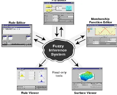
Fig 2 Fuzzy Interference System
In this section we'll be building a simple tipping example using the graphical user interface (GUI) tools provided by the Fuzzy Logic Toolbox. Although it's
possible to use the Fuzzy Logic Toolbox by working strictly from the command line, in general it's much easier to build a system graphically. There are five primary GUI tools for building, editing, and observing fuzzy inference systems in the Fuzzy Logic Toolbox. These GUIs are dynamically linked, in that changes you make to the FIS using one of them, can affect what you see on any of the other open GUIs. You can have any or all of them open for any given system.
The FIS Editor handles the high level issues for the system: as how many input and output variables used, & their names. The Fuzzy Logic Toolbox doesn't limit the number of inputs. However, the number of inputs may be limited by the available memory of your machine. If the number of inputs is too large, or the number of membership functions is too big, then it may also be difficult to analyze the FIS using the other GUI tools. The Membership Function Editor is used to define the shapes of all the membership functions associated with each variable. The Rule Editor is for editing the list of rules that defines the behavior of the system.
Fig 3 The Primary GUI Tools of the Fuzzy Logic Toolbox The Rule Viewer and the Surface Viewer are used for looking at, as opposed to editing, the FIS. They are strictly read-only tools. The Rule Viewer is a Matlab-based display of the fuzzy inference diagram shown in fig 4.2. Used as a diagnostic, it can show which rules are active, or how individual membership function shapes are influencing the results. The Surface Viewer is used to display the dependency of one of the outputs on any one or two of the inputs that is, it generates and plots an output surface map for the system.
will, if necessary, update related windows. Thus if the names of the membership functions are changed using the Membership Function Editor, those changes are reflected in the rules shown in the Rule Editor. The editors for any number of different FIS systems may be open simultaneously. The FIS Editor, the Membership Function Editor, and the Rule Editor can all read and modify the FIS data, but the Rule Viewer and the Surface Viewer do not modify the FIS data in any way. We'll start with a basic description of a two-input, one-output tipping problem. The basic tipping problem as Given a number between 0 and 10 that represents the quality of service at a restaurant (where 10 is excellent), and another number between 0 and 10 that represents the quality of the food at that restaurant (again, 10 is excellent), what should the tip be?
The starting point is to write down the three golden rules of tipping, based on years of personal experience in restaurants.
If the service is poor or the food is rancid, then tip is cheap.
If the service is good, then tip is average.
If the service is excellent or the food is delicious, then tip is generous.
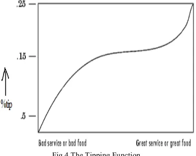
By assuming that an average tip is 15%, a generous tip is 25%, and a cheap tip is 5%. It's also useful to have a vague idea of what the tipping function should look like. A simple tipping function is shown as in Fig.2.11. Obviously the numbers and the shape of the curve are subject to local traditions, cultural bias, and so on, but the three rules are pretty universal. Now we know the rules, and we have an idea of what the output should look like. Let's begin working with the GUI tools to construct a fuzzy inference system for this decision process.
Fig 4 The Tipping Function b) The Membership Function Editor:
The Membership Function Editor shares some features with the FIS Editor. In fact, all of the five basic GUI tools have similar menu options, status lines, and Help and Close buttons. The Membership Function Editor is the tool that displays and edits all of the membership
functions associated with all of the input and output variables for the entire fuzzy inference system.
When open the Membership Function Editor to work on a fuzzy inference system that does not already exist in the workspace, there is not yet any membership functions associated with the variables that have to just defined with the FIS Editor. On the upper left side of the graph area in the Membership Function Editor is a "Variable Palette" that lets you set the membership functions for a given variable. To set up your membership functions associated with an input or an output variable for the FIS, select an FIS variable in this region by clicking on it.
Next select the Edit pull-down menu, and choose Add MFs new window will appear, which allows selecting both the membership function type and the number of membership functions associated with the selected variable. In the lower right corner of the window are the controls that change the name, type, and parameters (shape), of the membership function, once it has been selected.
The membership functions from the current variable are displayed in the main graph. These membership functions can be manipulated in two ways. The first thing use the mouse to select a particular membership function associated with a given variable quality, (such as poor, for the variable, service), and then drag the membership function from side to side. This will affect the mathematical description of the quality associated with that membership function for a given variable. The selected membership function can also be tagged for dilation or contraction by clicking on the small square drag points on the membership function, and then dragging the function with the mouse toward the outside, for dilation, or toward the inside, for contraction. This will change the parameters associated with that membership function.
Below the Variable Palette is some information about the type and name of the current variable. There is a text field in this region that changes the limits of the current variables range (universe of discourse) and another that sets the limits of the current plot (which has no real effect on the system).
The process of specifying the input membership functions for this two input tipper problem is as follows:
Select the input variable, service, by double-clicking on it. Set both the Range and the Display Range to the vector [-1 1].
Fig 5 Add Membership function Window
Use the pull-down tab to choose trimf for MF Type and 5 for Number of MFs. This adds three Triangular curves to the input variable service. Click once on the curve with the leftmost hump.
Change the name of the curve to NB. To adjust the shape of the membership function, either use the mouse, as described above, or type in a desired parameter change, and then click on the membership function. The default parameter listing for this curve is [-1.5 -1 -0.4].
Name the curve with the middle hump as NS, and the curve with center hump as ZO , the curve with the rightmost hump as PS and PB. Reset the associated parameters if desired. Select the input variable as Error, by clicking on
it. Set both the Range and the Display Range to the vector [-1 1].
Select Add MFs. from the Edit menu and add five trimf curves to the input variable Error. Click once directly on the curve with the
leftmost triangle, Change the name of the curve to NB. To adjust the shape of the membership function, either use the mouse, as described above, or type in a desired parameter change, and then click on the membership function. The default parameter listing for this curve is [-1.5 -1 -0.4].
Name the curve with the rightmost triangle is PB, and reset the associated parameters if desired.
Next there is a need to create the membership functions for the output variable duty ratio. To create the output variable membership functions, use the Variable Palette on the left, selecting the output variable, tip. The inputs ranged from -1 to 1, but the output scale is going to be a tip between 5 and 25 percent. Use triangular membership function types for the output. First, set the Range (and the Display Range) to [-1 1], to cover the output range. Initially, the NB membership function will have the parameters [-1.5 -1 -0.4], the ZE membership function will be [-0.4 0 0.4], and the PB membership function will be [0.4 1 1.5].
Fig 6 The Membership Function Editor
Now that the variables have been named, and the membership functions have appropriate shapes and names, it is ready to write down the rules. To call up the Rule Editor, go to the View menu and select Edit rules or type rule edit at the command line.
V MATLAB/SIMULINK RESULTS
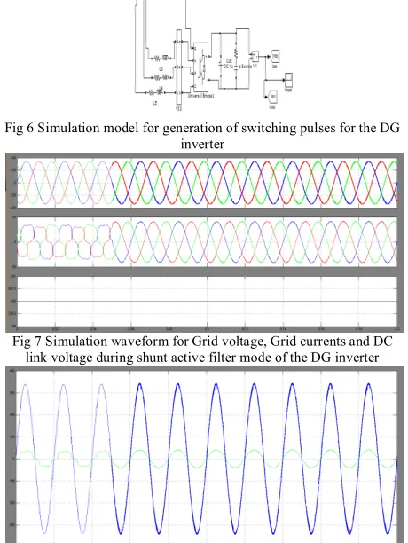
Fig 6 Simulation model for generation of switching pulses for the DG inverter
Fig 7 Simulation waveform for Grid voltage, Grid currents and DC link voltage during shunt active filter mode of the DG inverter
Fig 9 Simulation waveform for Grid voltage, Grid current and DG current in phase a under forward power flow mode
Fig 10 Simulation waveform for forward reactive power
Fig 11 Simulation waveform for Grid voltage, Grid current and DG current in phase a under forward mode
Fig 12 Simulation waveform for reverse reactive power
Fig 13 Simulation waveform for Grid voltage, Grid current and DG current in phase a under reverse mode
Fig 14 Simulation waveform for Grid voltage, Grid current and DG current in phase a under reverse power flow mode
Fig 15 Simulation waveform for DG Real power under non ideal supply conditions using open loop and closed loop control
Fig 16 Simulation waveform for Fundamental current tracking in Closed loop control
Fig 17 Simulation waveform for Dynamic performance of the proposed closed loop power control
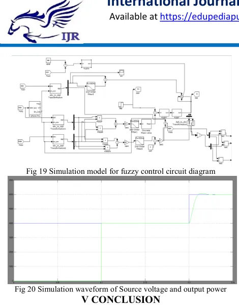
Fig 19 Simulation model for fuzzy control circuit diagram
Fig 20 Simulation waveform of Source voltage and output power V CONCLUSION
This paper discusses the capabilities of a MFGCI for enhancing the power quality in a grid connected distributed generation system. It has been shown that the DG inverter can be effectively utilized to inject real power from the RES in the forward and reverse power flow modes and/or operate as a shunt active power filter. The proposed closed loop active power control strategy achieves accurate power tracking with zero steady state errors under ideal and non-ideal supply conditions and can be used as a control technique for integration of DG inverters to the utility grid. The method laminates the need of extra power conditioning devices to improve the power quality. The effectiveness of the control scheme is verified under balanced and unbalanced non linear load conditions. With the proposed method the combination of nonlinear loads and the DG inverter is seen as a resistive load at the PCC and the grid currents re maintained sinusoidal.
REFERENCES
[1] F. Blaabjerg, R. Teodorescu, M. Liserre, and Adrian V.Timbus," Overview of Control and Grid Synchronization forDistributed power Generation Systems," IEEE Trans. Ind. Electron., vo1.53,no.5, pp.1398-1409, Oct. 2006
[2] J. Rocabert, A. Luna, F. Blaabjerg and P.Rodrigues, Control ofPower Converters in AC Microgrids," IEEE Trans. PowerElectron., vol. 27, no.11, pp.4734-4748, Nov. 2012
[3] I.EI-Samahy and E.EI-Saadany, "The effect of DG on PowerQuality in a deregulated environment," in Proc. IEEE PESGM. 2005, pp. 2969-2976
[4] F. Blaabjerg, Z. Chen,and S. Kjaer, "Power Electronics asefficient interface in dispersed power
generation systems," IEEETrans. Power Electron.,vol. 19,no. 5, pp. 1184-1194, Sep. 2004.
[5] IEEE Standardfor Interconnecting Distributed Resources withElectric Power Systems, IEEE Std. 1547, 2003.[6] S.Rahmani, N. Mendalek, K. AI-Haddad, "Experimental design of a nonlinear control technique for three phase shunt activepower filter," IEEE trans. Ind. lectron, voI.57,no.lO,oct 2010. [7] N. Pogaku and T.C.Green, "Harmonic mitigation throughout adistribution system- A distributed generator based solution,"lEE Proc. Gener.Transm.Distrib, vol. I53, No.3, pp. 350-58,May 2006.
[8] Z. Zeng, H.Yang, R. Zhao and C. Cheng, " Topologies andcontrol strategies of multifunctional grid connected inverters forpower quality enhancement: A comprehensive review,Renewable and Sustainable Energy Reviews,24, pp 223-270,2013.
[9] C.lGajanayake,D.M. Vilathgamuwa, P.c. Loh, R. Teodorescuand F. Blaabjerg, " Z-Source -Inverter-based flexible distributedgeneration system solution for grid power quality improvement," IEEE Trans. Energy Conv, vol. 24,no.3, pp.695-704, Sept.2009.
[10] J. He, Y.W. Li, F. Blaabjerg, " Flexiblemicrogrid power quality enhancement using adaptive hybrid voltage and currentcontroller." IEEE trans. Ind. Electron.. 61. no.6. June 2014.
[11] M. Singh, S. Member, V. Khadkikar, A. Chandra, and S.Member, "Grid Interconnection of renewable energy sources atthe distribution level with power-quality improvement features,"IEEE Trans. Power Delivery vol. 26, no. I, pp. 307-315, 2011.
[12] E. Pouresmaeil, C. M - Espinar, M. M - Campos,D. M- Miracleand O. G -Bellmunt, "A Control technique for integration ofDGunits to the Electrical networks," IEEE Trans. Power Electron.,vol. 60, no. 7, pp. 2881-2893, July 2013.
[13] Z. Zeng, H Yang, Q Tang, R Zhao, " Objective-oriented powerquality compensation of multifunctional grid -tied inverters andits application in Microgrids," IEEE Trans. Power Electron.,vo1.30, no.3, pp. 1255 1265, March 2015.
[14] 1 He, Y.Wei Li, F,Blaabjerg, X.Wang, "Active harmonicfiltering using current-controlled grid – connectedDG units withclosed loop power control," IEEE Trans. Power Electron., vol. 29, no. 2, pp. 642-653, Feb. 2014.
[15] H.Akagi, E.H. Watanabe,andM.Aredes, InstantaneousPowerTheory and Applications to Power Conditioning, Hoboken, NJ:Wiley-IEEE Press, Feb. 2007.