Reduce the Surge Current Error Caused the Distribution System Generation SFCL
1.
SHAIK JILANI PASHA,2.
N. PUNNA RAO
1PG Scholar, Department Of EEE,Sri Sai Educational Society's Group of Institutions, Kodad. 2Assistant Professor, , Department Of EEE,Sri Sai Educational Society's Group of Institutions, Kodad.
ABSTRACT
The main aim of project is to tranquilize of the current and voltage under abnormal conditions in distribution system by using active type super conducting fault current limiter. In Today’s World Electric Energy Utilization is increasing day by day ,The Utilization energy mainly in Industry, Home ,Business and Transportation ,To meet the demand Decentralizing Generating units are started .As a result there is increase in size of the generating station and inter connected network’s. Due to increase in size of the Grids and Generating station also possible of abnormal operations in the system, Due to fault leads to decrease the impedance of power system network. There may be increase of current known as Fault current and based on type of faults the voltage value changes. In this paper, the influence on the voltage compensation type, active superconducting fault current limiter (ASFCL) is investigated under symmetrical and asymmetrical fault conditions. ASFCL is consisting of air-core superconducting transformers and a three-phase voltage source converter. In the normal (no fault) state the flux in air core is compensated to zero. So the ASFCL has no influence on the main circuit. Using MATLAB SIMULINK, model of the three phase AC system with ASFCL is created and control strategies test, fault current limiting test, and distance relay operation is investigated. The utilization of fault current limiters (FCLs) in power system provides an effective way to suppress fault currents and result in considerable saving in the investment of high capacity circuit breakers.
Index Terms:
Active type super conducting
fault current limiter (ASFCL), Distribution
system, Over voltage, Short circuit current, Air
core super conducting transformer, Voltage
source converter
I.INTRODUCTION
limiters (FCL) are regarded as the suitable solution to solve excessive fault current problems. Active superconducting fault current limiter (ASFCL) voltage compensation type is a novel topology of FCL. This type SFCL not only preserves the merits of bridge type SFCL such as the automatic switch to the current limiting mode and without the quench of the superconductor, but also has the particular abilities of controlling the steady fault current and compensating active and reactive power for AC main circuit in the normal state. In view of that the introduction of a SFCL can impact the coefficient of grounding, which is a significant contributor to control the induced overvoltage’s amplitude, the change of the coefficient may bring positive effects on restraining over voltages. We have proposed a voltage compensation type active SFCL.
II. ANALYSIS OF SUPER CONDUCTING FAULT
CURRENT LIMITER (SFCL)
A. SUPERCONDUCTING FAULT CURRENT LIMITER
Superconducting Fault Current Limiter (SFCL) is innovative electric equipment which has the capability to reduce the fault current level within the first cycle of fault current [1]. The first-cycle suppression of fault current by a SFCL results in an increased transient stability of the power system carrying higher power with greater stability. The concept of using the superconductors to carry electric power and to limit peak currents has been around since the discovery of superconductors and
the realization that they possess highly non-linear properties. More specifically, the current limiting behavior depends on their nonlinear response to temperature, current and magnetic field variations. Increasing any of these three parameters can cause a transition between the superconducting and the normal conducting regime. The term ―quench‖ is commonly used to describe the propagation of the normal zone through a superconductor. Once initiated, the quench process is often rapid and uncontrolled. Though once initiated the quench process is uncontrolled, the extent of the normal region and the temperature rise in the materials can be predicted.
B. STRUCTURE AND PRINCIPLE OF THE ACTIVE SFCL
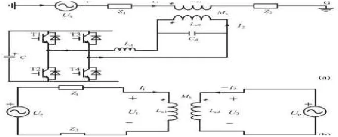
As shown in Fig. 1(a), it denotes the circuit structure of the single-phase voltage compensation type active SFCL, which is composed of an air-core superconducting transformer and a voltage-type PWM converter.Ls1, Ls2 are the self-inductance of two superconducting windings, and Ms is the mutual inductance.Z1is the circuit impedance andZ2is the load impedance. Ld and Cd are used for filtering high order harmonics caused by the converter. Since the voltage-type converter’s capability of controlling power exchange is implemented by regulating the voltage of AC side, the converter can be thought as a controlled voltage source Up. By neglecting the losses of the transformer, the active SFCL’s equivalent circuit is shown in Fig. 1(b).
In normal (no fault) state, the injected current (I2) in the secondary winding of the transformer will be controlled to keep a certain value, where the magnetic field in the air-core can be compensated to zero, so the active SFCL will have no influence on the main circuit. When the fault is detected, the injected current will be timely adjusted in amplitude or phase angle, so as to control the superconducting transformer’s primary voltage which is in series with the main circuit, and further the fault current can be suppressed to some extent. Below, the suggested SFCL’s specific regulating mode is explained. In normal state, the two equations can be achieved.
Controlling I2 to make jωLs1 I˙1 − jωMs I˙2 = 0 and the primary voltage U1 will be regulated to zero. Thereby, the equivalent limiting impedance ZSFCL is zero (ZSFCL = U1/I1), andI2 can be set as ˙ I2 = ˙Us_Ls1/Ls2/(Z1 + Z2)k, where k is the coupling coefficient and it can be shown as k = Ms/ √Ls1Ls2.Under fault condition (Z2 is shorted), the main current will rise from I1 to I1f , and the primary voltage will increase to U1f .
I˙1f =( ˙Us + jωMs I˙2)/(Z1 + jωLs1) ˙U1f =jωLs1 I˙1f − jωMs I˙2
=˙Us(jωLs1) − I˙2Z1(jωMs)Z1 + jωLs1. The current-limiting impedance ZSFCL can be controlled in:
ZSFCL =˙U1fI˙1f= jωLs1 −
jωMsI˙2(Z1+jωLs1)˙Us+jωMI˙a.
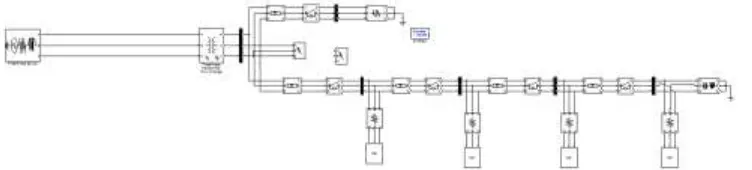
Fi g. 2 . Appl i c a ti on of the a c ti ve SFCL i n a di s tr i buti on s ys tem wi th DG uni ts .
According to the difference in the regulating objectives of I2, there are three operation modes:
1) MakingI2 remain the original state, and the limiting impedanceZSFCL−1=Z2 (jωLs1)/(Z1+Z2+jωLs1).
2) ControllingI2to zero, andZSFCL−2=jωLs1.
3) Regulating the phase angle of I2 to make the angle difference between˙ Us and jωMs˙I2 be 180◦.Bysetting
jωMs I2=−c˙Us, and ZSFCL−3=cZ1/(1−c)+jωLs1/(1−c).
The air-core superconducting transformer has many merits, such as absence of iron losses and magnetic saturation, and it has more possibility of reduction in size, weight and harmonic than the conventional iron-core superconducting transformer. Compared to the iron-core, the air-core can be more suitable for functioning as a shunt reactor because of the large magnetizing current , and it can also be applied in an inductive pulsed power supply to decrease energy loss for larger pulsed current and higher energy transfer efficiency . There is no existence of transformer saturation in the air-core, and using it can ensure the linearity of ZSFCL well.
As shown in Fig. 2, it indicates the application of the active SFCL in a distribution network with multiple DG units, and the buses B-E are the DG units’ probable installation locations. When a single-phase grounded fault occurs in the feeder line 1 (phase A, k1 point), the SFCL’s mode 1 can be automatically triggered, and the fault current’s rising rate can be timely controlled. Along with the mode switching, its amplitude can be limited further. In consideration of the SFCL’s effects on the induced overvoltage, the qualitative analysis is presented. In order to calculate the over voltages induced in the other two phases (phase B and phase C), the symmetrical component method and complex sequence networks can be used, and the coefficient of grounding G under this condition can be expressed as G=−1.5m/(2 +m)±j√3/2, where m=X0/X1, and X0 is the distribution network’szero-sequencereactance,X1is the positive-sequence reactance [6]. Further, the amplitudes of the B-phase and C B-phase over voltages can be described as:
Where UAN is the phase-to-ground voltage’s root mean square (RMS)under normal condition.
III. SIMULATION RESULTS
For purpose of quantitatively evaluating the current-limiting and overvoltage-suppressing characteristics of the active SFCL, the distribution system with DG units and the SFCL is created in MATLAB. The SFCL is installed in the behind of the power supply Us, and two DG units are included in the system, and one of them is fixedly installed in the Bus B (named as DG1). For the other DG, it can be installed in an arbitrary position among the Buses C–E (named as DG2). The model’s main parameters are shown in Table I. To reduce the converter’s design capacity, making the SFCL switch to the mode 2 after the fault is detected, and the detection method is based on measuring the main current’s different components by Fast Fourier Transform (FFT) and harmonic analysis.
FI G 3 .SI MULI NK MO DEL THE ACTI VE SFCL I N A DI STRI BUTI O N SYSTEM W I TH DG UNI TS
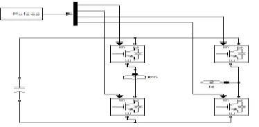
FI G 5 . SI MULI NK MO DEL O F I NTERNAL CI RCUI T O F AN ACTI VE TYPE SFCL
Overvoltage-Suppressing Characteristics of
the SFCL
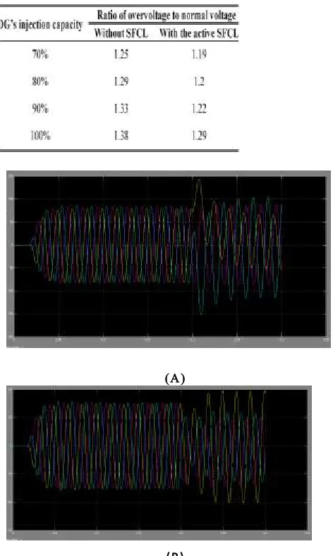
Supposing that the injection capacity of each DG is about 80% of the load capaci ty (load 1), and the fault location is k1 point (phase-A is shorted), and the fault time is t = 0.2 s, the simulation is done when the DG2 is respectively installed in the Buses C, D, and E, and the three cases are named as case I, II, and III. Fig. 4 shows the SFCL’s overvoltage-suppressing Characteristics and the waveforms with and without the SFCL are both listed. For the cases I, II, and III, the overvoltage’s peak amplitude without SFCL will be respectively 1.14, 1.23, 1.29 times of normal value, and once the active SFCL is applied, the corresponding times will drop to 1.08, 1.17, and 1.2.
During the study of the influence of the DG’s injection capacity on the overvoltage’s amplitude, it is assumed that the adjustable range of each DG unit’s injection capacity is about 70% and 100% of the load capacity (load 1), the two DG units are located in the Buses B and E, and the other fault conditions are unchanged, Table II shows the overvoltage’s amplitude characteristics under this background. Along with the increase of the DG’s injection capacity, the overvoltage will be accordingly rise, and once the injection Capacity is equal or greater than 90% of the load capacity, the overvoltage will exceed acceptable limit (1.3 times). Nevertheless, if the active SFCL is put into use, the limit-exceeding problem can be solved effectively.
(A)
(B)
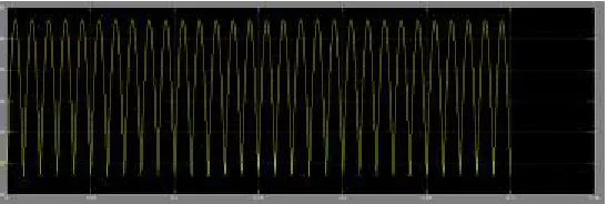
FI G 7. LINE CURRENT WAVEFORMS WHEN THE THREE-PHASE SHORT-CIRCUI T O CCUR AT K3 PO I NT. (A) W I THO UT SFCL AND (B) W I TH THE ACTI VE SFCL.
Current-Limiting Characteristics of the SFCL
By observing the voltage compensation type active SFCL’s installation location, it can be found out that this device’s current-limiting function should mainly reflect in suppressing the line current through the distribution transformer. Thereupon, to estimate the most serious fault characteristics, the following
FI G 8. ACTIVE SFCL’S CURRENT-LIMITING PERFORMANCES UNDER DI FFERENT FAULT LO CATI O NS.(A) K2 PO I NT
FI G 9. ACTIVE SFCL’S CURRENT-LIMITING PERFORMANCES UNDER DI FFERENT FAULT LO CATI O NS.(B) K1 PO I NT.
FI G 10.INFLUENCE OF INITIAL FAULT ANGLE ON PEAK AMPLI TUDE O F THE A -PHASE SHO RT-CI RCUI T CURRENT W I THO UT SFCL
Along with the decrease of the distance between the fault location and the SFCL’s installation position, the current-limiting ratio will increase from 12.7% (k1 point) to 21.3% (k2 point). Besides, as one component of fault current, natural response is an exponential decay DC wave, and its initial value has a direct relationship with fault angle. Through the application f the active SFCL, the influence of initial fault angle on the peak amplitude of the A-phase short-circuit current is analyzed in Fig. where the fault location is k3 point. It can be seen that, under the conditions with and without the SFCL, the short circuit Current’s peak amplitude will be smallest when the fault angle is about 130◦. At this fault angle, the power distribution system can immediately achieve the steady transition from Normal state to fault state.
IV. CONCLUSION
In this paper, the application of the active SFCL into in a power distribution network with DG units is investigated. For the power frequency overvoltage caused by a single-phase grounded fault, the active SFCL can help to reduce the overvoltage’s amplitude and avoid damaging the relevant distribution equipment. The active SFCL can as well suppress the short-circuit current induced by a three-phase grounded fault effectively, and the power system’s safety and reliability can be improved. The study of a coordinated control method for the renewable energy sources and the SFCL becomes very meaningful, and it will be performed in future. in recent years ,more a nd more dispersed energy sources, such as wind power and photovoltaic solar power , are installed into distribution systems.
REFERENCES
[1] S. Conti, ―Analysis of distribution network protection issues in presence of dispersed generation, ‖Elect. Power Syst. Res., vol. 79, no. 1, pp. 49–56, Jan. 2009.
[2] A. S. Emhemed, R. M. Tumilty, N. K. Singh, G. M. Burt, and J. R. McDonald, ―Analysi s of transient stability enhancement of LV connected induction
micro generators by using resistive-type fault current limiters,‖ IEEE Trans. Power Syst., vol. 25, no. 2, pp. 885–893, May 2010.
[3] S.-Y. Kim and J.-O. Kim, ―Reliability evaluation of distribution network with DG considering the reliability
of protective devices affected by SFCL,‖IEEE Trans. Appl. Supercond., vol. 21, no. 5, pp. 3561–3569, Oct. 2011.
[4] S. A. A. Shahriari, A. Yazdian, and M. R. Haghifam, ―Fault current limiter allocation and sizing in distribution system in presence of distributed generation,‖ in Proc. IEEE Power Energy Soc. Gen. Meet., Calgary, AB, Canada, Jul. 2009, pp. 1–6. [5] S. Hemmati and J. Sadeh, ―Applying superconductive fault current limiter to minimize the impacts of distributed generation on the distribution protection systems,‖ in Proc. Int. Conf. Environ. Electr. Eng., Venice, Italy, May 2012, pp. 808–813.
[6] S.-H. Lim, J.-S. Kim, M.-H. Kim and J.-C. Kim, ―Improvement of protection coordination of protective devices through application of a SFCL in a power distribution system with a dispersed generation,‖ IEEE Trans. Appl. Supercond., vol. 22, no. 3, p. 5601004, Jun. 2012.
[7] L. Chen, Y. Tang, J. Shi, and Z. Sun, ―Simulations and experimental analyses of the active superconducting fault current
[8] L. Chen, Y. Tang, J. Shi, Z. Li, L. Ren, and S. Cheng, “Control strategy for three-phase four-wire PWM converter of integrated voltage com-pensation type active SFCL,” Phys. C, vol. 470, no. 3,pp. 231-235, Feb. 2010
[9]J. Wang, L. Zhou, J. Shi, and Y. Tang, “Experimental investigation of an active superconducting current controller,” IEEE Trans. Appl. Supercond., vol. 21, no. 3, pp. 1258–1262, Jun. 2011.
1016, Jun. 1997.
[11] H. Yamaguchi, T. Kataoka, H. Matsuoka, T. Mouri, S. Nishikata, and Sato, “Magnetic field and electromagnetic force analysis of 3-phase air-core superconducting power transformer,” IEEE Trans. Appl. Supercond., vol. 11, no. 1, pp. 1490–1493, Mar. 2001.
[12]M. Song, Y. Tang, N. Chen, Z. Li, and Y. Zhou, “Theoretical analysis and experiment research of high temperature superconducting air-core transformer,” in Proc. Int. Conf. Electr. Mach. Syst., Wuhan, China, Oct. 2008, pp. 4394–4397.
[13]R. Wu, Y. Wang, Z. Yan, W. Luo, and Z. Gui, “Design and experimental realization of a new pulsed power supply based on the energy transfer between two capacitors and an HTS air-core pulsed transformer,” IEEE Trans. Plasma [14]S. Chen, W. Wang, and P. Yang, “Effects of current-limiting inductor on power frequency over voltages in transmission line,” Power Syst. Technol., vol. 34, no. 3, pp. 193–196, Mar. 2010.
.