P a g e | 428
Fuzzy Logic Control Based Torque Ripple
Minimization in Brushless DC Motor using
Modified SEPIC Converter
BELLAM PRAVEEN KUMAR M-tech Student Scholar
Department of Electrical & Electronics Engineering, Anurag Group Of Institutions (An Autonomous Institution),
Venkatapur (Vill), Ghatkesar (Mandal); Medchal (Dt); Telangana, India
CH. SRINIVASA RAO Associate Professor
Department of Electrical & Electronics Engineering, Anurag Group Of Institutions (An Autonomous Institution),
Venkatapur (Vill), Ghatkesar (Mandal); Medchal (Dt); Telangana, India.
ABSTRACT: The generated torque ripples from the BLDC motor is the main issue that affects the drive performance of the BLDC drive system. In this concept, a new switching technique to minimize the torque ripples due to current commutation is proposed. The presented scheme has been implemented using a commercial and low-cost mid-range PIC microcontroller to generate the modified pulse width modulation (PWM) control signals. An analysis of phase current during commutation time is carried out. Simulation results verify the effectiveness of proposed method. Results had shown a smoother output torque and current produced in comparison with that using conventional PWM control technique with an average of 50 % reduction in the generated torque ripples. Brushless DC (BLDC) motor has a permanent magnet rotor and a wound field stator, which is connected to a power electronic switching circuit. The availability of high energy- density permanent magnet (PM) materials at competitive prices, the commercial availability of low-cost microtone- trolleys and reduction in cost of powerful fast digital signal processors (DSPs) along with the advances in semiconductor-tor power switches have opened up wider area for permanent magnet brushless motor drives to be a competitive solution meeting the market demands due to their control simplicity, low torque per weight ratio and compact construction. The proposed concept can be implemented to Communication Torque Ripple Reduction in Brushless DC Motor using current control technique by using Matlab/Simulink software
Index Terms: BLDC Motor, Modified, SEPIC Converter, Commutation Torque Ripple, dc link voltage control
I INTRODUCTION
Brushless DC Motor (BLDCM), has been widely used in industries that require high reliability and precise control due to its simple structure, high power density and wide speed range [1]. Torque ripple, which occurs during commutation period, has always been one major factor in preventing BLDCM from achieving high performance. Two general approaches have been proposed to reduce the torque ripple. The first approach is to improve the motor‟s geometrical structure [2]. The second approach is to control the winding currents to overcome the disturbances [3]. More studies are being done to identify the sources, characteristics and minimization of torque ripple [3] . A new approach to optimize
current waveform based on d-q frame, which results in minimum torque ripple and maximum efficiency of BLDC motor drives is proposed in [6]. DTC is applied to BLDC Motor drives to achieve instantaneous torque control and reduced torque ripple is described in [7]. The commutation torque ripple and its compensation technique have been analyzed theoretically in [8].
Researchers introduced some special topology of a circuit to BLDCM drives to control its input voltage in [11]. In, the current slopes of the incoming and outgoing phases in the commutation period are equalized. In [12], a buck converter is used, and commutation torque ripple is greatly reduced at low speed. In [13], a super lift Luo converter is placed at the front of the inverter to produce desired DC link voltage and the commutation torque ripple is reduced at high speed. Those methods suffer from slow voltage adjustment and can achieve torque pulsation reduction only in low or high speed regions. A ne w approach of minimizing commutation torque ripple for BLDCM based on Single ended primary inductor converter (SEPIC) is presented in [14]. But the conventional SEPI C has pulsating output current similar to buck boost converters. In addition, the SEPIC converter transfers all its energy via the series capacitor so a capacitor with high capacitance and current handling capability is required.
P a g e | 429 II COMMUTATION TORQUE RIPPLE IN
BLDCM
Ideally, the current drawn by the BLDCM, with trapezoidal back EMF, takes the form of rectangular waveform [8] as shown in Fig.1. This kind of current waveform will produce a constant torque.
Fig.1. Ideal Current and back emf waveform
Practically, the smoothness in torque waveform is not observed and torque ripple is prevalent. Various non – linearity in the machine will result in the disruption of the ideal rectangular current waveform thereby resulting in torque ripple. The excitation current waveforms do not change instantaneously and a variable commutation time for different speeds is observed [18] as shown in Fig.2.
Fig.2. Commutation Currents and Torques
During this commutation time, Torque ripple occurs due to the difference between the time taken by the ongoing phase „b‟ current to reach the saturation value an d the time taken by the off going phase „a‟ current decay to zero.
In order to eliminate the dip in the Torque waveform, the difference in the commutation time for ongoing and off going phase currents should be made zero [18] as shown in Fig.3. This torque dips can be reduced by suitable dc link voltage control method during the commutation time. This can be achieved by using proposed MSEPIC in B LDCM drives.
Fig.3. Current waveform for the torque ripple compensation
III MODIFIED SEPIC CONVE RTER
The circuit topology of the conventional SEPIC Converter [19] is presented in Fig.4
Fig.4. Conventional SEPIC Converter
The wide range of input voltages can be realized because of the step-up and step down static gains of SEPIC converter. However, SEPIC converter suffers from higher voltage and current stress [19]. This disadvantage can be eliminated by using the proposed M-SEPIC converter circuit. Here, the modification of the SEPIC converter is accomplished by including diode Dm and capacitor Cm as shown in Fig.5.
Fig.5. Modified SEPIC Converter
A multiplier cell (Cm and D ) reduces the switch
stress in the proposed converter. The capacitor Cmis
charged with the output voltage of the classical boost converter. Hence, the voltage applied to the inductor L2 during conduction is higher compared with the
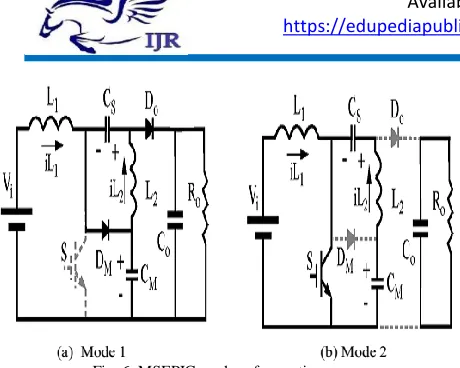
P a g e | 430 Fig. 6. MSEPIC modes of operation
The continuous conduction- mode (CCM) operation of the MSEPIC converter presents the following two modes.
1)Mode 1: In this mode the switch S is turned-off as shown in Fig.6(a) and the energy stored in the input inductor L1 is transferred to the output through
the capacitor Cs and output diode Do, and also to the
capacitor Cm through the diode Dm. Therefore, the
switch voltage is equal to the capacitor Cm voltage.
The energy stored in t he inductor L2 is transferred to
the output through the diode Do.
2)Mode 2: In this mode the s witch S is turned-on and the diodes Dm and Do are blocked as shown in
Fig.6(b), and the inductors L1 and L2 store energy.
The input voltage is applied to the input inductor L1
and the voltage (Vcs – Vcm) is applied to the inductor L2. The voltage Vcm is higher than the voltage Vcs.
The inductor L1 current is equal to the input current and the inductor L2 current is equal to the output current.
III PROPOSED TORQUE RIPPLE MINIMIZ ATION TOPOLOGY FOR BLDCM
A Modified SEPIC Converter with a switch over IGBT for implementing the dc link voltage adjustment is shown in Fig.7.
Fig. 7. Configuration of BLDCM driving system with MSEPIC Converter
In Fig. 7, S1, S2, S3 are power MOSFET s. By
operating S1 appropriately, the energy storage
components L1, L2, Cs, C0 and Cm of the M-SEPIC
can be adjusted to get the desired voltage. S2 and S3
are switched over power MOSFETs used for choosing between the inputs of the inverter Vs and
the output voltage of the MSEPIC Vo.
Vo can be calculated as
(1) Where, D is the Duty ratio. Em is proportional to speed, i.e.,
(2)
Where Ke is the back EMF co-efficient and ω is the speed of the machine. Then, the duty ratio of S1 for satisfying Vo = 4Em from [14] can be calculated by
(3) According to above equation, the duty ratio of S1
corresponding to the desired dc link voltage can be estimated by measuring the motor speed. The relationship between the duty ratio and speed is shown in Fig.8. The duty ratio calculations are done by assuming the input voltage Vs as 200V.
Fig.8. Duty ratio with respect to speed
P a g e | 431
regulating again, and its output voltage will reach the expected value before the next commutation. The flowchart for the proposed method is clearly indicated in Fig.9.
Fig. 9. Flowchart of the proposed method for one electrical cycle
IV.INTRODUCTIONTOFUZZYLOGIC
CONTROLLER
A new language was developed to describe the fuzzy properties of reality, which are very difficult and sometime even impossible to be described using conventional methods. Fuzzy set theory has been widely used in the control area with some application to dc-to-dc converter system. A simple fuzzy logic control is built up by a group of rules based on the
human knowledge of system behavior.
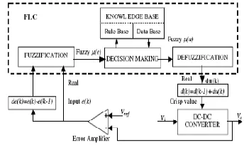
Matlab/Simulink simulation model is built to study the dynamic behavior of dc-to-dc converter and performance of proposed controllers. Furthermore, design of fuzzy logic controller can provide desirable both small signal and large signal dynamic performance at same time, which is not possible with linear control technique. Thus, fuzzy logic controller has been potential ability to improve the robustness of dc-to-dc converters. The basic scheme of a fuzzy logic controller is shown in Fig 5 and consists of four principal components such as: a fuzzy fication interface, which converts input data into suitable linguistic values; a knowledge base, which consists of a data base with the necessary linguistic definitions and the control rule set; a decision-making
logic which, simulating a human decision process, infer the fuzzy control action from the knowledge of the control rules and linguistic variable definitions; a de-fuzzification interface which yields non fuzzy control action from an inferred fuzzy control action [10].
Fig.10. General structure of the fuzzy logic controller on closed-loop system
The fuzzy control systems are based on expert knowledge that converts the human linguistic concepts into an automatic control strategy without any complicated mathematical model [10]. Simulation is performed in buck converter to verify the proposed fuzzy logic controllers.
Fig.11. Block diagram of the Fuzzy Logic Controller (FLC) for dc-dc converters
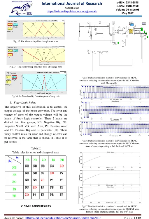
A. Fuzzy Logic Membership Functions:
P a g e | 432 Fig. 12.The Membership Function plots of error
Fig.13. The Membership Function plots of change error
Fig.14. the Membership Function plots of duty ratio
B. Fuzzy Logic Rules:
The objective of this dissertation is to control the output voltage of the boost converter. The error and change of error of the output voltage will be the inputs of fuzzy logic controller. These 2 inputs are divided into five groups; NB: Negative Big, NS: Negative Small, ZO: Zero Area, PS: Positive small and PB: Positive Big and its parameter [10]. These fuzzy control rules for error and change of error can be referred in the table that is shown in Table II as per below:
Table II
Table rules for error and change of error
V. SIMULATION RESULTS
Fig 15 Matlab/simulation circuit of conventional for SEPIC converter reducing commutation torque ripple in BLDCM drive
with PI controller
Fig 16 Matlab/simulation circuit of conventional for SEPIC converter reducing commutation torque ripple in BLDCM wave
form of current operating at full, half and 3/4th load
Fig 17 Matlab/simulation circuit of conventional for SEPIC converter reducing commutation torque ripple in BLDCM wave
P a g e | 433 Fig 18 Matlab/simulation circuit of conventional for SEPIC
converter reducing commutation torque ripple in BLDCM wave form of torque operating at full, half and 3/4th load
Fig 19 Matlab/simulation circuit of proposed method for SEPIC converter reducing commutation torque ripple in BLDCM drive
with fuzzy logic
Fig 20 Matlab/simulation circuit of conventional for SEPIC converter reducing commutation torque ripple in BLDCM wave
form of current operating at full, half and 3/4th load
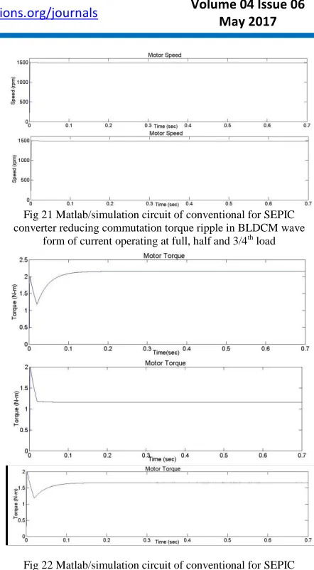
Fig 21 Matlab/simulation circuit of conventional for SEPIC converter reducing commutation torque ripple in BLDCM wave
form of current operating at full, half and 3/4th load
Fig 22 Matlab/simulation circuit of conventional for SEPIC converter reducing commutation torque ripple in BLDCM wave
form of current operating at full, half and 3/4th load.
VI.CONCLUSION
In this project a fuzzy logic topology based on Modified SEPIC converter is analyzed for reducing commutation torque ripple in BLDCM drives. The reduction in voltage and current stress of the main switches are the main advantage of this topology. Simulation is done for wide range of speeds and from the results it is apparent that the torque ripple is effectively reduced. Fuzzy logic implementation of BLDCM drive with conventional control is done using FPGA. The close correlation between simulation results illustrate the relevance of the topology for torque ripple minimization.
REFERENCES
[1] C. Xia, Y. Xiao, W. Chen, T. Shi, “Torque Ripple Reduction in Brushless DC Drives Based on Reference Current Optimization Using Integral Variable Structure Control,” IEEE Transactions on Industrial Electronics, vol. 61, no. 2, pp. 738-752, Feb. 2014.
P a g e | 434 [3] H. Le-Huy, R. Perret, and R. Feuillet, “Minimization of
torque ripple in brushless DC motor drive,” IEEE Trans. Ind. Applicat., vol. 22, pp. 748–755, July/Aug. 1986.
[4] T. M. Jahns, “Torque production in permanent magnet synchronous motor drives with rectangular current excitation,” IEEE Trans. Ind. Applicat., vol. 20, pp. 803–813, July/June 1984. [5] D. C. Hanselman, “Minimum torque ripple, maximum efficiency excitation of brushless permanent magnet motors,” IEEE Trans. Ind. Appl., vol. 41, no. 3, pp. 292–300, Jun. 1994. [6] S. J. Park, H. W. Park, M. H. Lee, and F. Harashima, “A new approach for minimum-torque-ripple maximum-efficiency control of BLDC motor,” IEEE Trans. Ind. Electron., vol. 47, no. 1, pp. 109– 114, Feb. 2000.
[7] Y. Liu, Z. Q. Zhu, and D. Howe, “Direct torque control of brushless dc drives with reduced torque ripple,” IEEE Trans. Ind. Appl., vol. 41, no. 2, pp. 599–608, Mar./Apr. 2005.
[8] R. Carlson, M. L. Mazenc, and J. Fagundes, “Analysis of torque ripple due to phase commutation in brushless DC machines,” IEEE Trans. Ind. Appl., vol. 28, no. 3, pp. 632–638, May/Jun. 1992.
[9] J. H. Song and I. Choy, “Commutation torque ripple reduction in brushless dc motor drives using a single dc current sensor,” IEEE Trans. Power Electron., vol. 19, no. 2, pp. 312–319, Mar. 2004.
[10] D. K. Kim, K. W. Lee, and B. I. Kwon, “Commutation torque ripple reduction in a position sensorless brushless dc motor drive,” IEEE Trans. Power Electron., vol. 21, no. 6, pp. 1762– 1768, Nov. 2006.
[11] K.Y. Nam, W.T. Lee, C.M. Lee, and J.P. Hong, “Reducing torque ripple of brushless DC motor by varying input voltage,” IEEE Trans. Magn., vol. 42, no. 4, pp. 1307–1310, Apr. 2006.
[12] X. F. Zhang and Z. Y. Lu, “A new BLDC motor drives method based on BUCK converter for torque ripple reduction,” in Proc. IEEE Power Electron. Motion Control, Conf., pp. 1–4, 2006.
[13] W. Chen, C. L. Xia, and M. Xue, “A torque ripple suppression circuit for brushless DC motors based on power dc/dc converters,” in Proc. IEEE Ind. Electron. Appl., Conf., pp. 1453– 1457, 2008.
[14] T. Shi, Y. Guo, P. Song, and C. Xia, “A New Approach of Minimizing Commutation Torque Ripple for Brushless DC Motor Based on DC–DC Converter,” IEEE Transactions On Industrial Electronics, vol. 57, no. 10, pp. 3483-3490, October 2010.
[15] Y. Liu, Z. Q. Zhu, and D. Howe, “Instantaneous torque estimation in sensorless direct-torque-controlled brushless dc motors,” IEEE Trans. Ind. Appl., vol. 42, no. 5, pp. 1275–1283, Sep./Oct. 2006.
[16] J. H. Song and I. Choy, “Commutation torque ripple reduction in brushless dc motor drives using a single dc current sensor,” IEEE Trans. Power Electron., vol. 19, no. 2, pp. 312–319, Mar. 2004.
[17] D. K. Kim, K. W. Lee, and B. I. Kwon, “Commutation torque ripple reduction in a position sensorless brushless dc motor drive,” IEEE Trans. Power Electron., vol. 21, no. 6, pp. 1762– 1768, Nov. 2006.
[18] I. Kim, N. Nakazawa, S. Kim, C. Park, C. Yu, “Compensation of torque ripple in high performance BLDC motor drives,” Elsevier Journal on Control Engineering Practice, vol.18, pp. 1166–1172, 2010
[19] P.F. Melo, R. Gules, E.F.R. Romaneli, and R.C. Annunziato, “A Modified SEPIC Converter for High-Power-Factor Rectifier and Universal Input Voltage Applications,” IEEE Transactions on Power Electronics, vol. 25, no. 2, pp. 310 – 321, Feb. 2010.
[20] S. M. Shakouhi, M. Mohamadian, E. Afjei, “Torque ripple minimisation control method for a fourphase brushless DC motor with non-ideal back electromotive force,” IET Electric Power Applications, vol. 7, no. 5, pp. 360–368, 2013.
Authors Profile:
BELLAM PRAVEEN KUMAR Received B.Tech from Holy Mary Institute of Technology and Science, in the year 2014 and now pursuing M.Tech in the stream of Power Electronics and Electrical Drives at Anurag Group of Institutions (An Autonomous Institution), Venkatapur (Vill), Ghatkesar (Mandal), Medchal (District), Telangana. His areas of interests are Electrical Machines, Power Electronics and Power systems.
CH. SRINIVASA RAO (ASSOCIATE
PROFFESOR) DEPARTMENT OF EEE .He has
completed degree in engineering (AMIE) from the institution of engineers (India), Kolkata in the year 1995. He obtained post graduation in Industrial drives and Control (IDC) from Osmania University in the year 2008. He has industrial experience about 20 years in steel industry, jaguar aircraft, manufacturing of special electrical machines and maintenance of
various electrical equipment etc.
He has academic teaching