On Various Design of Micro Strip Patch
Antenna Survey
Shankar M.Patil1, Pramod.A.kulkarni2
Assistant Professor, Department of Electronics and Telecommunication, MBE society’s College of Engineering
Ambajogai, India1
H.O.D and Professor, Department of Electronics and Telecommunication, MBE society’s College of Engineering
Ambajogai, India2
ABSTRACT: Due to fast advancement in wireless communication technology, use of small size antenna has rapidly improved. Not only the size of the antenna its cost, performance, ease of installation everything have been taken care while designing the antenna. To meet this entire requirement micro-strip antenna is proposed. Nowadays microstrip antennas are used in many places such as aircrafts, spacecraft’s, satellite and missile applications. In this paper, we discuss the microstrip antenna, types of microstrip antenna, a variety of substrates used for designing the antenna and the literature survey which we have done.
KEYWORDS: Antenna radiation, Electromagnetic waves (EM), Micro strip patch antenna (MPA), Micro strip slot antenna (MSA).
I.INTRODUCTION
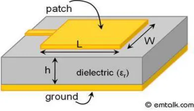
Antenna is a transducer designed to transmit or receive electromagnetic waves (EM). Microstrip antenna has several advantages over conventional antenna. It consists of a radiating patch on one side of dielectric substrate and has a ground plane on other side. Microstrip antennas are used for many commercial purposes due to their light weight and low cost. The recent demands of compact wireless devices propel the demand of pattern reconfigurable antennas. Reconfigurable microstrip antenna provides numerous application and offer more versatility as compared to conventional antennas which offer one function in a single antenna. They can provide diversity function in operating frequency, radiation pattern and polarization to mobile communications. The main disadvantages of microstrip patch antenna radiation performance including narrow bandwidth. Various techniques have been included to overcome these disadvantages.Microstrip patch antenna and side view of micro strip patch antenna as shown bellow figure1 and figure2 respectively.
Figure1: Micro strip patch Antenna.
Table 1: Characteristics of MPA and MSA
Sl.NO Characteristics MPA MSA
1 Polarization Both linear and
Circular
Both linear and circular
2 Dual frequency operation Possible Possible
3 Shape flexibility Any shape Mostly rectangular
and circular
4 Spurious Radiation Exists Exists
5 Bandwidth 2-50% 5-30%
6 Fabrication Very easy Easy
MPA-Microstrip patch antenna MSA-Microstrip slot antenna II.FEEDING TECHIQUES
Various types of feeding techniques are available to feed microstrip antenna. Each of them has their own merits or demerits. A number of factors are used to choose which type of feeding is suitable for the designed antenna. The main consideration is effective power transfer from feed line to the antenna radiating element that is proper matching between the feed and antenna. Various techniques like impedance transformer, stubs are used for impedance matching. Feed structure should like that these matching structure could be fabricated with radiating element easily. Spurious feed radiation and surface wave losses are also the major factors which depend on the feeding methods which affects the antenna characteristics. Surface waves decreases the efficiency of antenna and spurious feed radiation results in undesired radiation which will give rise to side lobe level and also increases level of cross polarization. Another main feature is that feed network should be well-suited to make an array, feeding methods can be dividing in two categories one is contacting feeds and other one is non contacting feeds or electromagnetic coupled feed. In contacting feeds the feed line is directly connected to radiating element. The main drawback of contacting feeds are that it shows inherent asymmetry which produces the higher order modes that leads to increase in cross polarization level. To minimize these noncontacting feeds are used. Microstrip line feed and coaxial probe feeding are two mainly used direct contact feedings and aperture coupled and proximity coupling are two noncontacting couplings which are described in brief below.
MICROSTRIP LINE FEED:
Microstrip line fed is conducting strip, usually of much minor width compared to patch. It is easy to fabricate, simple to match by controlling the inset position. If we increases the thickness of the substrate surface waves and spurious fed radiation increases. And its bandwidth is very limited. The purpose of the inset cut in the patch is to match the impedance of the fed line to the patch, without the need for any additional matching element. This is achieved by properly controlling the inset position.Microstrip line feed as shown bellow figure 3.
COAXIAL FEED:
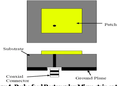
One of the commonly used feeding for microstrip antenna. In this type of feeding core of coaxial cable is directly connected to the patch using the soldering and the outer cable is connected to the ground. Core conductor is inserted in the substrate via a hole. The main advantage of this feeding is that we can directly feed or connect the inner conductor to the feed point where the input impedance is equal to the characteristic impedance of the feed line. Probe feed rectangular micro strip antenna as shown bellow figure 4.
Figure4: Probe feed Rectangular Micro strip antenna
PROXIMITY COUPLE FEED:Two types of dielectric substrates are used in this type of feeding. Microstrip line is not directly connected to patch and left open ended and is sandwiched between the substrates. Energy from feed line is coupled electromagnetic to the radiating patch. The microstrip line can be extended as stub to increase the bandwidth. Substrates dielectric constants play a lead role and selected to increase the bandwidth and decrease the spurious feed radiations from the feed line. Proximity coupled feed as shown bellow figure 5.
Figure 5: Proximity Couple Feed
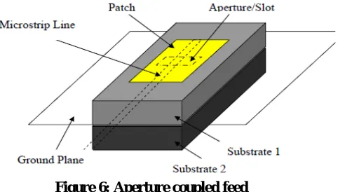
Thick Material with low dielectric constant is chosen for Upper substrates because lower the dielectric constant more the fringing field and more the radiations from patch and thin substrate with high dielectric constant is chosen for lower substrate. This type of feeding has largest bandwidth as compared to others. It is easy to model and has low spurious feed radiation however its fabrication is more difficult because the exact alignment of feed line is required.
Figure 6: Aperture coupled feed III.LITERATURE SURVEY
1. CIRCULAR POLARIZATION WIDEBAND E-SHAPED PATCH ANTENNA FOR WIRELESS APPLICATIONS
Here, polarization switching is presented for reconfigurable wideband E-shaped patch antenna. This design consists of two slots which are switched on and off using pin diode. And, two antennas allowing switching either between linear and circular polarization or between two circular polarizations are demonstrated. This microstrip antenna operates at 2.45GHz frequencies. Antenna is constructed on grounded two layers of dielectric sheet (air and FR4), and a vertical probe connected from ground to the upper patch. The substrate FR4 with relative dielectric constant of 4.2, thickness of h=10mm, and loss tangent=0.02.
2. PATCH ANTENNA DESIGN ANALYSIS FOR WIRELESS COMMUNICATION
A simulation of sixteen (hexadecimal) faced microstrip patch antenna design using slot on the edge is discussed here. Here probe fed model is used. The simulated results of the antenna achieve the radiation parameters such as s-parameter radiation pattern and VSWR. In s-parameter. The parameter value reaches less than -10dB for the resonant frequencies 0.9GHz, 0.87GHz to 0.90GHz and VSWR value is obtained as less than 2 for that same frequency. This antenna will be useful for 900MHz band in wireless communication applications.
3. RECTANGULAR MICROSTRIP PATCH ANTENNA USING CO-AXIAL PROBE FEEDING TECNIQUE TO OPERATE IN S-BAND
Here, the design of antenna is based on rectangular microstrip antenna. Its operating frequency is from 2GHz to 2.5GHz. Substrate used here is Flame Retardant 4(FR4) with the thickness of 1.6mm and its dielectric constant is approximately 4.4 and fed type used here is probe-fed. The return loss of the antenna obtained is -23dB at the centre frequency of 2.25GHz. From this, it indicates that the 9.61% of power is reflected and 90.84% of power is transmitted. The bandwidth obtained from the return loss result is 2% which signifies 46MHz. A perfectly matched antenna would have a VSWR of 1:1. This indicates how much power is reflected back or transferred into a cable. VSWR obtained from this antenna design is 1.13dB which is approximately equals to 1.1:1. This indicates that the level of mismatch is not very high.
4. FREQUENCYRECONFIGURABLE MICROSTRIP CIRCULAR PATCH ANTENNA FOR WIRELESS DEVICES
Here, frequency reconfigurable circular antenna design is proposed. In this, antenna a circular patch antenna with circular slot using two pin diode at the centre frequency 10 GHz was designed and simulated frequency reconfiguration is achieved in the frequency range of 9.69-10.2GHz. The substrate used is FR-4 with its permittivity of 4.54 and thickness of 1.6mm. The dimensions of the microstrip circular patch element were calculated at the centre frequency of 10GHz by conventional design procedure. Here, electromagnetic simulation software was used to simulate the proposed structure. Frequency reconfigurations were achieved for three different cases.
Case ii) when one-diode is in on-state Case iii) when both diode is on on-state.
In first case, the return loss is 14.84dB at the resonant frequency of 9.69GHz. In second case, the return loss is -11.87dB at the resonant frequency of 9.83GHz.Whereas in third case, the return loss is -13.84dB at the resonant frequency of 10.18GHz.
5. RECONFIGURABLE MICROCHIP PATCH ANTENNA USING MEMS TECHNOLOGY
Here, the design of reconfigurable microchip patch antenna is based on MEMS technology. Operating frequency is in the range of 5-8GHz for the application of wireless communication has been designed. MEMS based switch is inserted in the patch to control its configuration patch antenna using switchable slots shows different resonant features with different states of the switch. Here, capacitive type MEMS switch is used. Fed line width is 1.5564mm and fed-line length is 2.456mm.in this design return loss of -10dB is obtained and VSWR lie in the range of 1-2 which is achieved for all frequencies. Resonant frequency of 6GHz was designed. Different operating frequency of 5.38, 5.68, 5.75GHz were obtained using RF MEMS switch.
6. DESIGN OF COMPACT MULTIBAND MICROSTRIP PATCH ANTENNAS
In this design, antenna for main wireless applications which lie in the band starting from 900MHz to 5.5GHz which includes the GSM (880-960) GPS (1568-1592 MHz) ,DCS (1710-1880MHz), and PCS(1850-1990MHz), UMTS(1920-2170MHz), IEEE 802.11 b/g(2400-2484) and WLAN IEEE802.11a bands (5.15-5.35GHz,5.725-5.825GHz). In this design different type of antenna such as i) rectangular fractal antenna ii) multi-standard patch antenna iii) circularly polarized microstrip patch antenna iv) E-shape and U-shape v) multi-multi-standard patch antenna. Gain and directivity is calculated for each antenna. This antenna will cover the wide band operation and can be applied to multiband wireless communication system due to its small size and low fabrication cost. Antenna gain and radiation pattern are tolerable at almost all bands of operation.
7. 2.45GHz MICROSTRIPPATCH ANTENNA WITH DEFECTED GROUND STRUCTURE FOR BLUETOOTH
Here, Analyzed rectangular patch antenna with DGS (Defected Ground Structure) for wireless application. Their antenna design simulated at 2.45GHz frequency. And their feeding technique is done by quarter transformer feeding. This feeding is generally used for impedance matching. Here, they used rectangular patch antenna. This patch antenna dimension is 15mmx18mm using the dielectric substrate having permittivity 3.2 and thickness is 0.762mm. The dimension of quarter transformer feed which is used for a rectangular patch antenna of the resonant frequency 5GHz are length 9.5mm and width 0.56mm and feed line width is 1.83mm which results in a high-quality match with 50ohm.
8. A FREQUENCY RECONFIGURABLE STACKED PATCH MICROSTRIP ANTENNA WITH APERTURE COUPLER TECHNIQUE
9. DESIGN OF COMPACT MICROSTRIP ANTENNA USING CERAMIC SUBSTRATE
Here, the proposed idea is to model the micro strip antenna with new material for substrate having very high dielectric constant. The basic idea of this paper is to get the desired functioning of micro strip patch antenna with less size with respect to height and width of the substrate as well as the patch with the use of ceramic substrate. The substrate used in this design is belongs to ceramic family which is named by forsterite. By using this ceramic family substrate efficient and concise antenna is designed. It gave the effect on the radiations and bandwidth of the antenna. This substrate has the dielectric constant 6.2. This substrate has low microwave loss, good insulation at high temperatures, and as smooth surface. This ceramic substrate has high coefficient of thermal expansion, it bonds easily with metals and glass. Its resonant frequency is equals to 1.80GHz with the help of this substrate the dimensions of the antenna are greatly reduced. The bandwidth efficiency and directivity of this suggested model is also enhanced at low cost. Moreover, due to such a high dielectric constant material reduces the robustness and mechanical stability of the antenna.
10. EFFECTS OF DIELECTRIC PERMITTIVITY ON RADIATION CHARACTERISTICS OF CO-AXIALLY FEED RECTANGULAR PATCH ANTENNA
In this paper author discuss about various dielectric materials and its effects on radiation characteristics of rectangular patch antenna such as resonance frequency, bandwidth, gain, return loss, input impedance, radiation pattern and current distributions are investigated. And the dielectric material selected here having zero loss tangents. Here there is only small space between radiating element and ground plane main power is radiated towards broad size co-axial probe feed is used, here outer conductor is connected to ground plane and the inner conductor of co-axial connector is extends through dielectric and soldered to patch. Inner conductor of co-axial cable transfers the power from strip line to micro strip antenna from slot in the ground plane. Here different substrates used to compare the return loss.
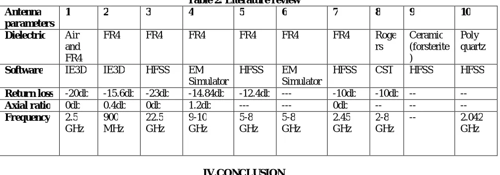
Table 2: Literature review Antenna
parameters
1 2 3 4 5 6 7 8 9 10 Dielectric Air
and FR4
FR4 FR4 FR4 FR4 FR4 FR4 Roge
rs Ceramic (forsterite ) Poly quartz
Software IE3D IE3D HFSS EM Simulator
HFSS EM
Simulator
HFSS CST HFSS HFSS
Return loss -20db -15.6db -23db -14.84db -12.4db --- -10db -10db -- --
Axial ratio 0db 0.4db 0db 1.2db --- --- 0db -- -- --
Frequency 2.5 GHz 900 MHz 22.5 GHz 9-10 GHz 5-8 GHz 5-8 GHz 2.45 GHz 2-8 GHz
-- 2.042
GHz
IV.CONCLUSION
Theoretical survey on micro strip patch antenna has done in this paper. While designing the antenna the things which we have to consider is substrate which we are going to use, feeding type, dielectric constant of the substrate and its height and width. When we use the substrate from the ceramic family it gives the low microwave loss and also good insulation at high temperature. Particular microstrip patch antenna can be designed for specific applications. And it is believed that, this small size antenna will continue to benefit the human race for upcoming years
REFERENCES
[1]. 1.Jeen-sheen Row and Jia-fu Tsai,” Frequency-reconfigurable Microstrip Patch Antennas with Circular Polarization”, IEEE Transactions And Wireless Propagation Letters,Vol.13,2014.
[3]. 3.Dr.Thirmurugan.T,Sundar .k,eta.,”Circular Polarization wideband E-shaped Patch Antenna for Wireless Applications”, International Journal of Engineering and Technical Research,Vol-2,Issue-3,March-2014.
[4]. 4.K.Praveen Kumar,K.Sanjeev Rao eta.,”The Effect of Dielectric Permittivity on Radiation Characteristics of Co-axially feed Rectangular Patch Antenna”,Intenational Journal of Advanced Research in Computer and Communication Engineering,Vol-2,Issue 2,Feb-2013.
[5]. 5.Truong Khang Nguyen and Ikmo park, “Effects of Antenna Design Parameter on The Characteristics Of a Terahertz Coplanar Strip line Dipole Antenna”, Progress in Electromagnetic and research,Vol-28,129-143,2013
[6]. 6.Alak Majumder,”Rectangular Microstrip patch antenna Using Coaxial Probe feeding Technique to operate in S-Band”. International Journal Of Engineering Trends and technology, Vol-4, Issue 4, April 2013.
[7]. 7.Arun Sharma,Jagatijit singh Chahal.”Design of Compact Micro strip Antenna Using ceramic Substrate”, Journal of Engineering Computers And Applied Sciences,Vol-2.No 6 ,June 2013.
[8]. 8.K.Praveen Kumar,K.Sanjeev Rao eta.,”The Effect of Dielectric Permittivity on Radiation Characteristics of Co-axially feed Rectangular Patch Antenna”,Intenational Journal of Advanced Research in Computer and Communication Engineering,Vol-2,Issue 2,Feb-2013.
[9].9 E. Ramola, Dr.T.Pearson,”Reconfigurable Microstrip Patch Antenna using MEMS:,IOSR Journal of Electronics And Communication Engineering,Vol-4,Issue 4(Jan-Feb 2013),PP 44-5
[10].10.K.S.Tamilselvan, S.Mahendrakumar,”Design Of Compact Multiband Microstrip Patch Antennas", Journal Of Global Research In Computer Science,Vol-3,No.11,NOV-2012.
[11]. 11.Rajeshwar Lal Dua, Himanushu Singh, Neha Gambhir,”2.45Ghz Microstrip Patch Antenna with Defected Ground Structure for Bluetooth”, International Journal of Soft Computing and Engineering, Vol-1,Issue-6,January-2012.
[12]. 12.N.Ramli,M.T.Ali,eta.,”Frequency Reconfigurable Stacked patch Micro strip Antenna with Aperture Coupler Technique,2012 IEEE Symposium On wireless Technology& Application,Sep 23-26,2012.
[13]. 13.B.Sai sandeep, S.Sreenath kashyap,”Design and Simulation of Microstrip Patch Array Antenna for Wireless Communications At 2.45Ghz”, International Journal of Scientific and Engineering Research, Vol-3, Issue-11, November-2012.