FREQUENCY DOMAIN NLMS ALGORITHM FOR ENHANCED JAM RESISTANT GPS RECEIVER
A. Kundu and A. Chakrabarty
Kalpana Chawla Space Technology Cell
Department of Electronics & Electrical Communication Engineering Indian Institute of Technology
Kharagpur-721302, West Bengal, India
Abstract—An optimal beamformer attempts to increase SNR at the array output by adapting its pattern to minimize some cost function. This is to say that, the cost function is inversely associated with the quality of the signal. Therefore by minimizing the cost function we can maximize signal at the array output. The primary optimal beamforming technique discussed in this paper will be MMSE, LMS, Frequency Domain LMS for GPS multipath reduction. In case of a GPS satellite, the DOA of the desired signal is mathematically known because the position of a satellite in an orbit is fixed at a particular time instant. So in some particular adaptive antenna algorithm the DOA of the desired signal is directly given as input.
1. INTRODUCTION
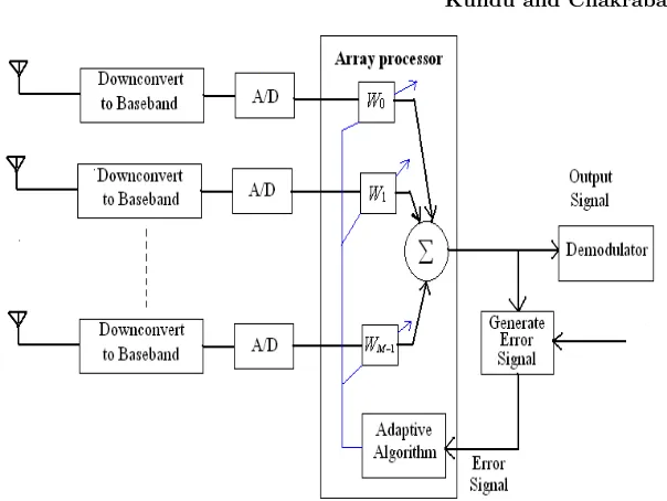
In the adaptive array processor shown in Fig. 1, the error signal is given as e(t) = u(t)−wHx(t), which is used to control the weights (w), where u(t) is the desired signal. The weights are adjusted such that the mean squared error (MSE) between the array output and the reference signal is minimized. The expression for squared error is e2(t) = [u(t)−wHx(t)]2. By taking expected value on both side of the equation we get, E[e2(t)] = E[u2(t)]−2wHz+wHRw, where
Figure 1. Adaptive array antenna with adaptive processor.
solve the normal equation directly. Since the DOA of the GPS signal & interferer signal both are time variable, the solution for weight vector must be updated. Furthermore, since the data required estimating the optimal solution is noisy, it is desirable to use an update equation, which uses previous solutions [6, 8, 11] for the weight vector to smooth the estimate of the optimal response, reducing the effect of interference. LMS algorithm [7, 9, 16] is based on the steepest descent method, a well known optimization technique that recursively computes and updates the weight vectors. The weight vectors are updated iteratively by estimating the gradient of the quadratic error surface and then changing the weights in the direction opposite to the gradient by a small amount, as to minimize the MSE and to increase SNR. At time t + 1, the update value of the weight vector is given by
2. MODIFIED LMS ALGORITHM
The step size parameterµgoverns the stability, convergence time and fluctuations of LMS adaptation process. One effective approach to overcome this dependence is to normalize the update step size with an estimate of the input signal variance σu2(t). Hence the weight update formula modified as
w(t+ 1 ) =w(t) + µ
N σ2 u(t)
x(t)e∗(t) (1 ) whereNis the tap length of the spatial filter [12, 17]. This modification leads to the asymptotic performance of the number of tapsN. hence convergence is strongly dependent on number of taps N. For large number of taps results is poorer i.e., poorer convergence rate. The use of active tap algorithm consistently improves the convergence rate of NLMS [1–3] algorithm.
3. FREQUENCY DOMAIN NLMS ALGORITHM
Figure 2 shows proposed frequency domain normalized LMS [4] algorithm with active tap detection. This scheme consists off two primary functions, firstly the adaptation process involving the update
of the tap weights of the system and the second one the active tap detection which determine which tap are to be updated. Hence the update equation modifies to,
W(k+ 1 ) =W(k) + µX(k)e ∗(k)
N (2)
Here e(k) is error waveform, X(k) is the FFT of the received signal+ noise. N is the number of taps. Error waveform is given by e(k) =
u(k)−x(k)wH. u(k) is transmitted signal & x(k) is the received signal +noise. Midst of large multipath & in the presence of multiple nearby intentional jammers NLMS algorithm suffers from poor convergence rate when number of taps is large, to rectify this problem the algorithm need to be slightly modified. We need to identify active and inactive regions within channel since elements of a smart antenna in the spatial domain correspond to different DOA’s hence we prefer sparsely spaced elements. So accordingly the equation modifies as
W(k+ 1 ) =W(k) + µX(k)e ∗(k) N
j=1
Aj(k)
(3)
Aj(k) is the active tap and j is the tap number. If the tap is active Aj = 1, otherwise for an inactive tap Aj = 0. Now the active tap detection become important & it will be determined based on some intuition. Here we form an activity measure based upon the active taps corresponding to the desired signal. The channel is taken to be LTI. The signal received at an antenna element m
is given by x(k) = r(k) +nn(k) where r(k) is the received signal and nn(k) is noise at sampling instant k. Now we need to find the activity measure M considering that we are reducing undesired signals relative to the desired signal. Let defineγ = [γ1, γ2, γ3, . . . , γN] and γ = K
k=1
u(k)x∗j(k). By taking the discrete Fourier transform of γ across the collection of antenna elements we acquire vector Γ, Γ = [Γ1,Γ2,Γ3, . . . ,ΓN]. The activity measure M for a spatial angle is finally given by M = Γ(k)Γ∗(k) where Γ is the discrete Fourier transform of γ. In order to discriminate between the active and passive taps some threshold has to be modeled. Let define T(k) =
2 log(kN) k
i=1
X(i)X∗(i)
k
i=1
u(i)u∗(i)
4. SIMULATED RESULT
Here we have used MatlabTM 7 as simulation platform. µ set as .008; 640 input signal samples of training sequence have signed value of 1 or−1to simulate a transmitter sending binary values. fc = 1575 MHz
L1 frequency. Hence λ = .19 m; to avoid the grating lobes we take
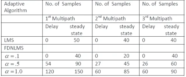
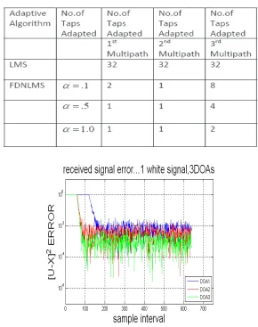
d=λ/2 =.095 m. Propagation delay from transmitter to receiver 1st antenna element is set as 70 ms. The performance of the frequency domain NLMS is examined in terms of convergence rates, number of active taps used and beam pattern. In order to create a realistic environment we have taken more than one multipath with different gain with both amplitude and phase components. Three DOA’s 60◦,30◦,−20◦ transmitted towards GPS receiver & each multipath [5] arrives at the antenna system with a difference of one sampling period 1/fc, so we can denote the signal arrives at antenna of a GPS receiver at time instant u(t), u(t−1), u(t−2). . .. The corresponding gains introduced to multipath have .5, .66, 1.0 amplitudes respectively. Three different weight vectors of frequency domain normalized LMS equations were used in processing the multipath simulation conducted for threshold control α values of .1, .5, 1.0. Here we show the convergence rate of each multipath in a tabular form referred to Table 1& in terms of the number of samples required to reach steady state. From Table 2 it is quite clear a narrower threshold leads to less taps being adapted, this comes as a cost of delay.
Table 2. No of taps adapted.
Figure 3. Received Signal error & convergence for FDNLMS.
5. DISCUSSION
The mean square error lies at approximately .005, .0015, .00034 for each multipath respectively after it converges. Results show an over all increase in convergence rate of approximately 15% compared to standard LMS algorithm from simulated results referred Fig. 3. α
Figure 4. DNLMS active number of taps for α=.1.
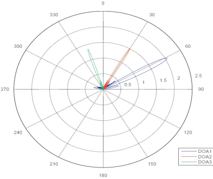
Figure 5. FDNLMSα=.1beam pattern for 2 multipath with 1DOA of desired signal.
Figure 6. True & estimated output GPS data signal after demodulataion.
REFERENCES
1. Homer, J., I. Mareels, and C. Hoang, “Enhanced detection-guided NLMS estimation of sparse FIR-modeled signal channels,” IEEE Transactions on Circuits and Systems I: Regular Papers, Vol. 53, Issue 8, 1783–1791, Aug. 2006.
2. Homer, J., “Detection guided NLMS estimation of sparsely parametrized channels,” IEEE Transactions on Circuits and Systems II: Analog and Digital Signal Processing, Vol. 47, Issue 12, 1437–1442, Dec. 2000.
3. Bellofiore, S., J. Foutz, R. Govindarajula, I. Bahceci, C. A. Bal-anis, A. S. Spanias, J. M. Capone, and T. M. Duman, “Smart antenna system analysis, integration and performance for mobile ad-hoc networks (MANETs),” IEEE Transactions on Antennas and Propagation, Vol. 50, Issue 5, 571–581, May 2002.
4. Farhang-Boroujeny, B. and K. S. Chan, “Analysis of the frequency-domain block LMS algorithm,” IEEE Transaction on Signal Processing, Vol. 48, Issue 8, 2332–2342, Aug. 2000.
5. Braasch, M. S., “GPS multipath model validation,” Position Location and Navigation Symposium, 1996, IEEE, 672–678, April 22–26, 1996.
6. Rocca, P., L. Manica, and A. Massa, “An effective excitation matching method for the synthesis of optimal compromises between sum and difference patterns in planar arrays,” Progress In Electromagnetics Research B, Vol. 3, 115–130, 2008.
7. Kazemi, S., H. R. Hassani, G. Dadashzadeh, and F. Geran, “Performance improvement in amplitude synthesis of unequally spaced array using least mean square method,” Progress In Electromagnetics Research B, Vol. 1, 135–145, 2008.
8. Lizzi, L., F. Viani, M. Benedetti, P. Rocca, and A. Massa, “The M-DSO-ESPRIT method for maximum likelihood Doa estimation,” Progress In Electromagnetics Research, PIER 80, 477–497, 2008. 9. Cengiz, Y. and H. Tokat, “Linear antenna array design with use
of genetic, memetic and tabu search optimization algorithms,” Progress In Electromagnetics Research C, Vol. 1, 63–72, 2008. 10. Gu, Y.-J., Z.-G. Shi, K. S. Chen, and Y. Li, “Robust adaptive
beamforming for steering vector uncertainties based on equivalent DOAs method,”Progress In Electromagnetics Research, PIER 79, 277–290, 2008.
PIER 79, 475–497, 2008.
12. Xue, W. and X.-W. Sun, “Multiple targets detection method based on binary Hough transform and adaptive time-frequency filtering,” Progress In Electromagnetics Research, PIER 74, 309– 317, 2007.
13. Mahmoud, K. R., M. El-Adawy, S. M. M. Ibrahem, R. Bansal, and S. H. Zainud-Deen, “A comparison between circular and hexagonal array geometries for smart antenna systems using particle swarm optimization algorithm,” Progress In Electromagnetics Research, PIER 72, 75–90, 2007.
14. Guney, K. and M. Onay, “Amplitude-only pattern nulling of linear antenna arrays with the use of bees algorithm,” Progress In Electromagnetics Research, PIER 70, 21–36, 2007.
15. Gozasht, F., G. Dadashzadeh, and S. Nikmhr, “A comprehensive performance study of circular and hexagonal array geometreis in the LMS algorithem for smart antenna applications,”Progress In Electromagnetics Research, PIER 68, 281–296, 2007.
16. Mukhopadhyay, M., B. K. Sarkar, and A. Chakrabarty, “Aug-mentation of anti-jam GPS system using smart antenna with a simple DOA estimation algorithm,”Progress In Electromagnetics Research, PIER 67, 231–249, 2007.
17. Mouhamadou, M., P. Vaudon, and M. Rammal, “Smart antenna array patterns synthesis: Null steering and multi-user beamforming by phase control,” Progress In Electromagnetics Research, PIER 60, 95–106, 2006.
18. Sanyal, S. K., Q. M. Alfred, and T. Chakravarty, “A novel beam-switching algorithm for programmable phased array antenna,” Progress In Electromagnetics Research, PIER 60, 187–196, 2006. 19. Mouhamadou, M., P. Armand, P. Vaudon, and M. Rammal,
![Figure 2 shows proposed frequency domain normalized LMS [4]algorithm with active tap detection.This scheme consists off twoprimary functions, firstly the adaptation process involving the update](https://thumb-us.123doks.com/thumbv2/123dok_us/7759324.1273264/3.612.143.383.389.590/frequency-normalized-algorithm-detection-twoprimary-functions-adaptation-involving.webp)