Wideband Microstrip-Line-Fed Suspended
Rectangular Microstrip Antenna
Suryakanth Nirate1, S.L.Mallikarjun2,R.M.Vani3, P.V.Hunagund4
Research Student, Dept. of Applied Electronics, Gulbarga University, Kalaburagi, Karnataka, India1
Guest Faculty, Dept. of Applied Electronics, Gulbarga University, Kalaburagi, Karnataka, India2
Professor & Head, USIC, Gulbarga University, Kalaburagi, Karnataka, India3
Professor & Chairman, Dept. of Applied Electronics, Gulbarga University, Kalaburagi, Karnataka, India4.
ABSTRACT:In this paper a wide band microstrip-line-fed suspended rectangular microstrip antenna is presented. The basic parameters of the antenna such as radiation pattern and return loss are simulated and measured by using IE3D software and Vector Network Analyzer. The antenna gives the wide bandwidth of the order of 44.97% which is 9 times more than that of reference antenna. A glass epoxy substrate is employed providing a good solution i.e. cheap both in material and manufacturing cost.
KEYWORDS: Microstrip antenna, Suspended, Wide band, Microstrip-Line-Feed, Rectangular, Air.
I.INTRODUCTION
The microstrip antenna now a days has become so popular because of its low cost, low profile and easy fabrication and conformabilities. However, they suffer from the disadvantage of narrow bandwidth. Many techniques were reported in literature to overcome the inherent disadvantage of narrow bandwidth of microstrip antennas. [1, 2]. Impedance matching techniques have been implemented to increase the bandwidth of the microstrip antenna [3]. Other method is to increase the bandwidth is the use of thicker substrate. This increases higher dielectric losses and hence lower efficiency and gain of the antenna.
To improve upon the bandwidth and efficiency of the microstrip antenna a suspended configuration is used [4, 5]. Here, an air gap is introduced between the patch and the ground plane that offers improved efficiency and enhanced bandwidth. Recently V. Gupta [4] has reported investigation on suspended microstrip patch antenna at X-band with dielectric resonator loading and he achieved about 12.3% impedance bandwidth. There have been many different element designs proposed for bandwidth improvement. In sense these can be categorized into the following methods: Impedance matching using co-planar and multiplayer parasitic elements and increasing antenna volume. The aim of this paper is to study the bandwidth and radiation characteristic of suspended rectangular microstrip antenna.
II.ANTENNA DESIGN
In the proposed design, the antennas have been designed for 6 GHz and are fed using microstrip line feed. In the
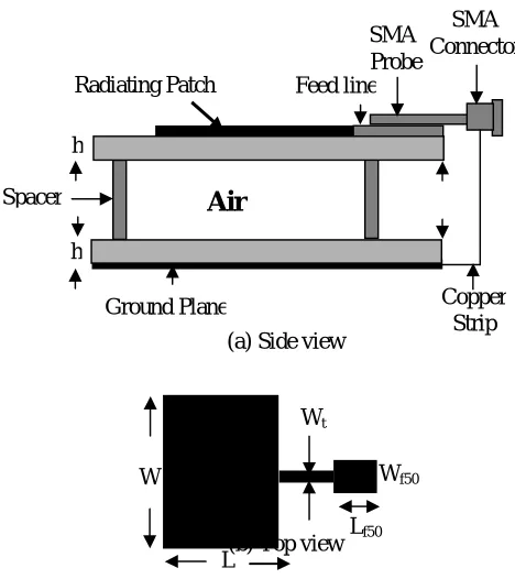
suspended rectangular microstrip antenna configuration, two layers of glass epoxy substrates (εr = 4.4, h = 1.6 mm and tan δ=0.0245) separated by air gap () is shown in Fig. 1. This method is equally useful for achieving the wide bandwidth with other patch geometries. The rectangular patch antenna has a length “ L ” and width “W”. The advantage of suspended technique is simplicity of design, since the single patch is used only on the top layer of glass epoxy substrate. The artwork after designing the microstrip antenna has been done in AUTOCAD-2006.
(a) Side view
(b) Top view
Fig. 1 Schematic diagram of suspended rectangular microstrip antenna
III.RESULTS AND DISCUSSION
Keeping the parameters h and εr fixed and varying two prototype suspended rectangular microstrip antennas have
been designed, fabricated, simulated and measured experimentally. Table 1. Shows the simulation results and the obtained experimental results are tabulated in Table 2.
As noted from Table.2 a variation in air gap () can affect the performance of the antenna. For our proposed antenna, the measured resonant frequency is 6.27GHz and hence, the corresponding bandwidth is 44.97%.
The reference antenna radiates at 5.77 GHz and gives the bandwidth 5.02%. After making the stacking i.e. when =0
mm there is increase in bandwidth. When antenna is constructed in suspended manner i.e.=1 mm the bandwidth is further increased as compared to earlier antenna. But one thing we realized that when the thickness is perfectly sufficient then bandwidth is increased. Hence the antenna-2 as gap () of 1 mm which gives the wide bandwidth of the order of 44.97% as compared to V. Gupta [4].
Table 1: IE3D Simulation results of Suspended Rectangular Microstrip antenna
Parameter & Antennas
Resonant frequency (GHz)
Return loss (dB)
Band width (%)
Reference
Antenna 5.85 -14.37 3.19
Antenna-1
= 0 mm 5.67 -19.78 16.96
Antenna-2
= 1 mm 6.75 -19.56 26.81
Air
Radiating Patch
SMA Probe
SMA Connector
Spacer
Ground Plane Copper
Strip Feed line
h
h
Wt
W
L
Wf50
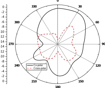
The radiation pattern of reference antenna (Fig. 2) shows wide band with better cross-polarization. The radiation pattern of the antenna-1 & antenna-2 are shown in Fig 3 & Fig 4 respectively. Antenna-1 & antenna-2 shows the maximum radiation in broadside direction. The proposed antenna is useful in wireless communication field.
Fig. 2 Radiation pattern of Reference antenna at 5.77GHz
Fig. 3 Radiation pattern of Antenna-1 at 6.05GHz
Parameter & Antennas Resonant frequency (GHz) Return loss (dB) Band width (%) Reference
Antenna 5.77 -21.15 5.02
Antenna-1
= 0 mm 6.05 -33.02 37.19 Antenna-2
= 1 mm 6.27 -39.74 44.97
Fig.4 Radiation pattern of Antenna-2 at 6.27GHz
IV.CONCLUSION
In this paper, a wide band microstrip-line-fed suspended rectangular microstrip antenna is presented. The bandwidth enhancement of the microstrip antenna is obtained by introducing an air gap between the patch and the ground plane. We have achieved 44.97% impedance bandwidth with an air gap () of 1 mm whereas it is 5.02% in case of reference antenna.
REFERENCES
[1] K.M.Luk, C.L. Mak, et al.,“Broadband microstrip antenna,” Electronics letters, Vol.34, 1998, pp.1442-1443.
[2] P.H.Rao, V.Fusco and R. Cahill, “Wideband Linear and circularly polarized patch antenna using printed stepped T-feed.” IEEE Trans.
Antennas and Propagation Vol.Ap-50, 2002. pp.356-361,
[3] H.F.Pues and A.R.Van de Capelle, “An impedance matching technique for increasing the bandwidth of microstrip antennas,” IEEE
Trans.Antennas and Propagation Vol.Ap-37, pp.1345-1354, 1989.
[4] V. Gupta,” Suspended microstrip patch antenna with dielectric resonator loading for enhanced bandwidth”, ieeexplore. ieee.org/iel5/7378/20029/00926080.pdf.
[5] Amit A. Deshmukh and Girish Kumar, “Compact Broadband Gap-Coupled Center shorted Rectangular Microstrip antennas”,
www.ee.iitb.ac.in/uma/ncc 2002/proc/˜NCC-2002/pdf/n169 pdf
BIOGRAPHY
Mr. Suryakanth Nirate received his M.Sc. Applied Electronics degree from Gulbarga University, Kalaburagi in the year 2002 and completed M.Phil. Degree in the year 2007 from same Department. He is pursuing his Ph.D degree in Dept. of Applied Electronics, Gulbarga University, Kalaburagi in the field of Microwave Electronics. His areas of interest include Suspended Microstrip Antennas.
Dr. S. L. Mallikarjun received his M.Sc., M.Phil. and Ph.D. degree in Applied Electronics from Gulbarga University, Kalaburagi in the year 2005, 2007 and 2011 respectively. He is working in Dept. of Applied Electronics, Gulbarga University, Kalaburagi. He is an active researcher in the field of Microwave Electronics. His area of interest includes microstrip antenna, arrays and dielectric resonator antenna. He has more than 70 publications in reputed International/National Journals and in conference and symposia.
-18 -16 -14 -12 -10 -8 -6 -4 -2 0
0
30
60
90
120
150
180 210
240 270
300 330
-18 -16 -14 -12 -10 -8 -6 -4 -2 0
Dr.Vani. R.M. received her B.E. in Electrical and Electronics from the B.I.ET., Davanagere, Karnataka, and M.Tech in Industrial Electronics from S.J.C.E., Mysore. She has received her Ph.D in Applied Electronics from Gulbarga University, Kalaburagi, India, in year 2005. She is working as Professor & Head, University Science Instrumentation Center, Kalaburagi, since 1995. She has more than 85 research publications in National and Intern
ational reputed journals and Conference proceedings. She presented many research papers in India & abroad. She has conducted several courses, workshops for the benefit of faculties and field engineers. Her areas of interest are microwave antennas, PC based Instrumentation, Embedded controllers and wireless communication. She has one UGC major research project to her credit.