Speed Control of an Induction Motor using
Raspberry PI
P. M. Palpankar 1, Shraddha Waghmare2, B. Shikkewal3
Assistant Professor, Department of Electrical Engineering, DBACER, Nagpur, Maharashtra, India1
Assistant Professor, Department of Electronics & communication Engineering, DBACER, Nagpur, Maharashtra, India2
Assistant Professor, Department of Electrical Engineering, PCE, Nagpur, Maharashtra, India3
ABSTRACT: The main objective of this project is to control the speed of INDUCTION MOTOR at lower cost and efficient performance. The induction motor speed variation can be easily achieved for a short range by stator voltage control. The terminal voltage across the stator winding of the motor can be varied for obtaining the desired speed control by controlling the firing angle of the semiconductor power devices (TRIAC in our project). RASPBERRY PI 2 (model B) plays an important in our project. Raspberry Pi has very small size and it is a low cost device. Raspberry Pi has a Quadcore broadcom BCM2836 900 MHz processor and 1GB RAM. It can perform the work like that of computer thus it can be referred as minicomputer. Python language must be used for this. And it uses Raspbian operating system based on Debian distribution of LINUX.
KEYWORDS: Induction motor, Raspberry Pi, Stator voltage control, TRIAC, Python
I. INTRODUCTION
Ac phase controlled switching is used for the speed control of single-phase induction motors but it introduces large higher order harmonics. An integral-cycle control method is also available but it introduces sub-harmonics in the line and the output voltage is adjustable in steps. For mitigating this situations, a discontinuous phase- controlled switching technique is given. The voltage control is done by a combination of the phase control and the integral-cycle switching. Voltage and step voltage are controlled by the former and the latter methods respectively. For fan type of loads, performance of the proposed controller improves when this technique is applied to control the main winding voltage only. In case of constant torque loads, voltage controllers including ac regulators offer a very limited speed control range. [1]
Recent advances in semi-conductor technology and implementation of micro-controller have made it easier to use AC Motors in speed control applications. This paper, deals with variable speed drives of induction motor for constant torque using V/F ratio method. Above system is designed with closed loop where the actual speed of motor is compared with the reference of speed. The difference in the speed is adjusted by changing firing angles of switching devices and there by obtaining variable speed. This system is tested for its performance and is also recorded under condition. Introduction of microcontroller in performing the speed control of the induction motor makes it more flexible when compared with other traditional methods. [2]
Induction motor is the most used in industry because of its high robustness, high efficiency and good self starting. In this paper rule-based Mamdani type fuzzy logic controller applied to closed loop Induction Motor model. Motor model is designed and membership functions are chosen according to the parameters of the motor model. Such results are obtained in Simulation. These results obtained in the simulation are interesting, considering the presence of strong nonIinearities in the 1M Model. Conventional PI controller is compared practically to fuzzy logic controller using Simulink. [4]
When connected with the main power supply, this induction motors run at their rated speed and there are many applications where variable speed operations is required. System consists of the control, driver and the power circuits. This circuit includes the power supply circuit and the microcontroller. Power circuit includes the full-bridge single-phase Pulse Width Modulated type of inverter. Simulation was done using MATLAB Simulink software. This system was implemented, tested and the experimental results are examined and discussed. [5]
The relation between rotor speeds of the Travelling wave ultrasonic motor and current drawn by TWUSM is not linear for the TWUSM under different loading condition. In order to solve this nonlinearities and variation problems of TWUSM, PI controller, frequency controller and phase difference controller are proposed and are implemented. Proposed system evaluates the steady-state performance of TWUSM drive system by using PI controller and current controller. Experimenting results of the proposed technique are analyzed and presented. [6]
This paper is based on Automatic Speed Control of Single Phase Induction motor with variation of ambient temperature. These circuitry of the systems comprises of temperature detector, control and loading circuit. The system has undergone a successful test approach and its behavior is observed by analyzing its temperature versus load curve. Various equation of the curve using Newton‟s Interpolation method is incorporated. Simulation approach is
incorporated. [7]
II. RELATED WORK Raspberry Pi
Raspberry Pi has very small size and low cost. Raspberry Pi has Quadcore broadcom BCM2836 900 MHz processor and 1GB RAM. It performs the work like that of computer thus it can be referred as minicomputer. It has to be work on Python language. And it uses Raspbian operating system based on Debian distribution of LINUX.
Fig.1 The Board configuration Python
individual commands. Command line program to execute standalone script. Integrated development environment (IDE) bundled with Python and the Raspberry Pi is called IDLE.
Triggering Circuit
The light is proportional to the signal, so this signal is thus transferred to the photo-transistors. Opto couplers may also comes in few module such as the SCR or photodiodes or TRIAC of other semiconductor switch.
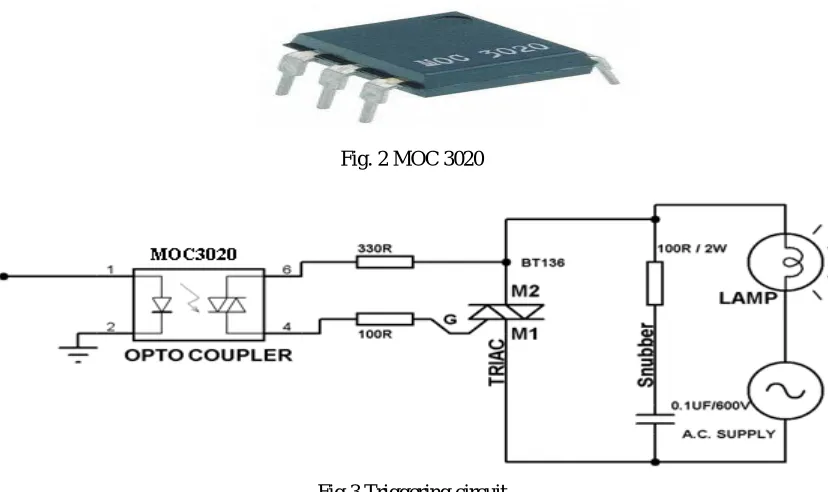
Fig. 2 MOC 3020
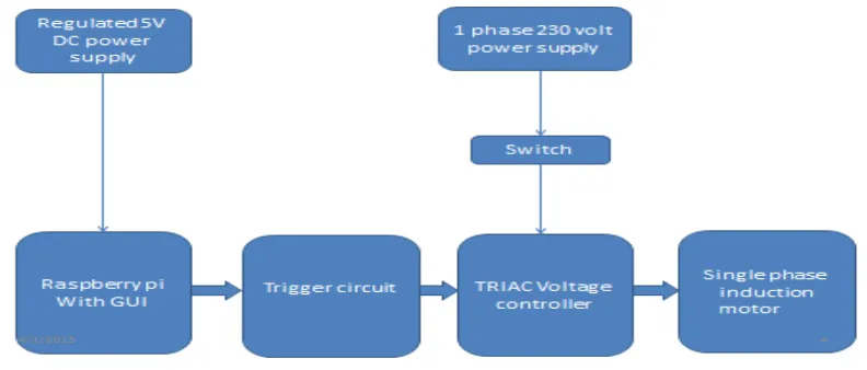
Fig 3 Triggering circuit Triac
A triac has a complex multiple-junction structure and it is an integration of a pair of phase-controlled thyristors connected in inverse-parallel on the same chip. In this figure the triac symbol and its volt-ampere characteristics has been shown. The three-terminal device can be triggered into conduction in both positive and negative half-cycles of supply voltage by applying gate trigger pulses. In I+ mode, the terminal T2 is positive and the device is switched on by positive gate current pulse.
Fig 4 Triac symbol Single Phase Induction Motor
III.HARDWARE DESIGN
Hardware consists of several prime sections which are as follows: DC power supply
A 5 V DC power supply is supplied to the Raspberry Pi to turn ON the Raspberry Pi circuit.
Raspberry PI
This device plays an important role in controlling the whole system.
It acts as a heart of the system which is then interfaced with triggering circuit. This interfacing between both circuits shares or transmit the data in the form of PWM signals to the triggering circuit.
Triggering Circuit (MOC 3020)
The input of the opto- coupler which also known as a triggering circuit (moc 3020) is connected with the output signals supplied through the raspberry pi circuit. This output signals make this triggering circuit
In conduction mode, it turned on and its output is then given to the triac section for further operation.
Triac as voltage controller
This is the voltage controlling section and plays a prime role in the hardware. This triac is out of conduction mode until the output of triggering circuit is given to the triac (i,e to the gate terminal).
A separate single phase ac supply is also given to the triac .
Single Phase AC supply
A separate Single phase 230ac, 50Hz supply is requirement of the triac section and to operate the single phase induction motor (the load to be varied).
Single Phase Induction Motor
The motor is used as a load in the hardware. The ac supply is given to the motor through the triac section .the output terminals of the triac is given to the motor for controlling the speed of motor through the snubber circuit.
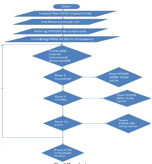
Fig. 5 Block Diagram of Hardware
IV.PROGRAMING OF RASPBERRY PI
Fig. 6 Flowchart
V. EXPERIMENTAL RESULTS
We select the percentage of duty cycle from the GUI of Raspberry Pi, according to that gate current and thus firing angle of Triac changes which further gives the variation in stator voltage of single phase Induction motor. Due to the change in stator voltage to the single phase IM, speed of the motor changes accordingly which is required
Output Table and graphs
Table No. 1
Sr. No Duty Cycle (%) Voltage (volt) Speed (RPM)
1 100 229.1 2660
2 90 228.5 2252
3 80 217 1968
4 70 207 1638
5 60 188 1436
6 50 171 1240
7 40 162 1000
8 30 154 377
9 20 81 22
10 10 54 15
11 0 2.72 0
We can draw a graph between
1) The voltage applied and the duty cycle. 2) The speed of IM and duty cycle. 3) The speed of IM and voltage applied.
The following plot shows the variations of stator voltage of motor with respect to the variation of duty cycle applied
Fig.7 Plot of voltage Vs Duty cycle
Above plot shows the variation in speed of motor with respect to the variation of duty cycle
Fig.8 Speed Vs Duty cycle
Above plot shows the variation in speed of motor with respect to the variation of duty cycle
VI.CONCLUSION
REFERENCES
1. M.Syed Jarnil Asghar,” Smooth Speed Control of Single-phase Induction Motors by Integral-Cycle Switching”, IEEE Transactions on Energy Conversion, Vol. 14, No. 4, December 1999.
2. Rabisankar Roy, Susmita Das, Jayanta Kumar Ray, Shreyashi Barat, Biswarup Neogi,” Automatic Speed Control of Single Phase Induction Motor with the Variation of Ambient Temperature”, International Journal of Scientific and Research Publications, Volume 2, Issue 11, November 2012.
3. K. Sandeep kumar, K. Pritam satsangi,” MICRO-CONTROLLER BASED CLOSED LOOP CONTROL OF INDUCTION MOTOR USING V/F METHOD”, IET-UK International Conference on Information and Communication Technology in Electrical Sciences (ICTES 2007), Dr. M.G.R. University, Chennai, Tamil Nadu, India. Dec. 20-22, 2007. pp.340-342.
4. Divya Asija,”Speed Control of Induction Motor Using Fuzzy-PI Controller”, 2010 2nd International Conference on Mechanical and Electronics Engineering (ICMEE 2010).
5. Mr. Aung Zaw Latt, Dr. Ni Ni Win,” Variable Speed Drive of Single Phase Induction Motor Using Frequency Control Method”, 2009 International Conference on Education Technology and Computer.
6. Puja Talukder, Prashant Kumar Soori, and Benetta Aranjo,” Speed Control of Induction Motor Drive Using Universal Controller”, 2012 IEEE International Power Engineering and Optimization Conference (PEOCO2012), Melaka, Malaysia: 6-7 June 2012.
7. Altan Gencer,” A Novel Microcontroller Based Speed Control Method Employing Current Controller for TWUSM”, 2013 3rd International Conference on Electric Power and Energy Conversion Systems, Yildiz Technical University, Istanbul, Turkey, October 2-4, 2013.
8. Muhammad.H.Rashid,” Power electronics circuits devices and applications”,3rd edition 2012. 9. Ashfaq Husain,”Electric Machines”, Dhanpat Rai & Co.,2nd edition 2011.
10. Ned Mohan,“Power Electronics Converters, Applications and Design”, John wiley and sons Inc., New Delhi, 3rd Edition 2006. 11. Deodatta Shingare, “Industrial and Power Electronics”, Electrotech publication, Satara, 4th Edition 2009.
12. P.S.Bhimra,”Power Electronics”, Khanna publication,3rd edition 2003.