GIRISH CHANDRA, HARSHA. Remote Data Collection and Analysis using Mobile Agents and Service-Oriented Architectures. (Under the direction of Dr. Frank Mueller).
The ubiquity of wireless systems have ushered us into a new era of mobile com-puting. With the emergence of superior input/output, communication hardware and cheap data services, mobile phones have become a bed for offering new and exotic services. Su-perior GUI and remote connectivity make mobile phones and PDAs good candidates for data collection, but lacking battery life and computational prowess, they are poor com-putational devices. We introduce a novel architecture that builds on agents on mobile phones as the front end and a service-oriented architecture composed of high performance devices as the back end. Agent-based computing, which has proved to be advantageous for desktops/servers, can also encompass handheld devices to provide us with new service management capabilities.
A thesis submitted to the Graduate Faculty of North Carolina State University
in partial fulfillment of the requirements for the Degree of
Master of Science
Computer Science
Raleigh, North Carolina
2008
APPROVED BY:
Dr. Helen Gu Dr. Nagiza Samatova
DEDICATION
ACKNOWLEDGMENTS
LIST OF TABLES . . . vii
LIST OF FIGURES . . . viii
1 Introduction . . . 1
1.1 Agent-Oriented Programming . . . 2
1.2 Service-Oriented Architectures . . . 3
1.3 Mobile Agents . . . 7
1.3.1 Mobile Agents as a Fluid SOA . . . 8
1.4 Remote Data Collection and Analysis . . . 8
1.4.1 Related Approaches to Remote Data Collection and Analysis . . . . 9
1.5 Mobile Agents Criticism . . . 13
1.6 System Overview . . . 14
1.7 The Main Contributions . . . 15
1.8 Thesis Hypothesis . . . 15
2 Design and Implementation . . . 18
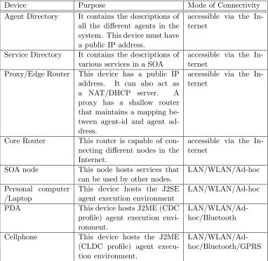
2.0.1 Description of the Network . . . 18
2.0.2 Agent Architecture Design of Ubimac . . . 21
2.0.3 Security Considerations . . . 22
2.0.4 Itinerant Agent Structure . . . 24
2.0.5 Agent Host Structure . . . 24
2.0.6 Design of Agent Directory . . . 26
2.0.7 Different Types of Agents. . . 27
2.1 Protocols . . . 28
2.1.1 Mobile Agent Creation . . . 28
2.1.2 Mobile Agent Arrival . . . 30
2.1.3 Mobile Agent Communication . . . 30
2.1.4 Mobile Agent Departure . . . 31
2.1.5 Exception Handling . . . 31
2.2 J2ME Technology . . . 32
2.2.1 J2ME Configurations and Profiles . . . 34
2.2.2 J2ME Development Environment . . . 36
2.3 Implementation of Mobile agents . . . 36
2.4 Interfacing with a Service-Oriented Architecture . . . 38
2.4.1 Comparison of Messaging Technologies . . . 39
3 High Performance Kernels on the Cell Processor . . . 43
3.1 Cell Broadband Engine Architecture . . . 43
3.1.1 Scaling the Performance-Limiting Walls . . . 44
3.2 Cell BE Architecture Elements . . . 45
3.2.1 Power Processing Element . . . 46
3.2.2 Synergistic Processing Elements . . . 46
3.2.3 Element Interconnect Bus . . . 47
3.2.4 DMA Transfers and Interprocessor Communication. . . 48
3.2.5 Run Time Environment . . . 49
3.3 Cell Application Affinity . . . 50
3.3.1 Cell Affinity Areas . . . 50
3.3.2 Cell Non-Applicable Areas . . . 50
3.4 Cell Programming Approach . . . 51
3.4.1 Bag-of-Tasks Paradigm . . . 53
3.4.2 Double Buffering Technique . . . 53
3.5 Text Mining Problem . . . 54
3.5.1 TF-IDF Algorithm . . . 56
3.5.2 Parallelization Technique . . . 57
3.5.3 Memory Handling . . . 59
3.5.4 Performance Gain. . . 59
3.6 Mersenne Twister . . . 61
3.6.1 Parallelizing the Original Algorithm . . . 63
3.6.2 Parallelizing Using Dynamic Creation Library . . . 66
3.7 Smith Waterman . . . 68
3.7.1 The Algorithm . . . 68
3.7.2 Approach . . . 69
3.7.3 Performance Gain . . . 69
4 Experimental Validation . . . 71
4.0.4 Experimental Results . . . 72
5 Related Work . . . 77
6 Conclusion and Future Work . . . 79
Table 1.1 Mobile agent solution for remote data collection . . . 10
Table 1.2 Mobile Agent Issues . . . 16
Table 1.3 Mobile Agent Issues... continued . . . 17
Table 2.1 Different devices in the system . . . 20
Table 2.2 Java Profiles . . . 35
Table 2.3 J2ME Development Environment . . . 37
Table 2.4 Comparison of various Messaging Technologies . . . 40
Table 3.1 Communication mechanisms . . . 47
Table 3.2 Cell Affinity [25] . . . 52
LIST OF FIGURES
Figure 1.1 Generic Agent Interpreter[1]. . . 3
Figure 1.2 Canonical view of an agent-based system [7] . . . 4
Figure 1.3 Basic service-oriented architecture . . . 6
Figure 1.4 Service Composition[6] . . . 7
Figure 1.5 Panoramic view of the system . . . 14
Figure 2.1 Transport Level Diagram . . . 19
Figure 2.2 Agent Architecture . . . 21
Figure 2.3 Itinerant Agent Structure . . . 25
Figure 2.4 Sequence Diagram of the operation . . . 29
Figure 2.5 Java Editions and their target markets . . . 33
Figure 2.6 Interfacing Mobile Agents with SOA . . . 41
Figure 3.1 Cell Architecture . . . 44
Figure 3.2 Bag of tasks paradigm . . . 53
Figure 3.3 Double Buffering [22]. . . 54
Figure 3.4 Text Mining . . . 55
Figure 3.5 TF-IDF algorithm. . . 58
Figure 3.6 Memory Handling Techniques . . . 60
Figure 3.7 TF-IDF Performance . . . 61
Figure 3.8 Mersenne Twister code (original) . . . 64
Figure 3.9 Mersenne Twister (divided into three loops) . . . 64
Chapter 1
Introduction
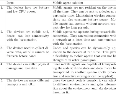
a high-level software abstraction that explains the software behavior in a specific context. Theweak notion of an agent is that it is reactive (responds to the environment), proactive (ability to act in anticipation of future goals) and autonomous (not centrally controlled). A strong notion of an agent is that it is any entity whose state is viewed of consisting of mental components ( e.g.,beliefs, capabilities, decisions and commitments) [1] . The actions of the agent are determined by its decisions. The decisions are constrained by beliefs that refer to
• states of the world,
• mental states of other agents, and
• capabilitiesof this and other agents
Thedecisionsare constrained by previous decisions. Capabilitiesdefine what an agent can do
at a particular time. Commitmentsdefine guarantees of an agent to another agent regarding a proposition. Adecisioncan be viewed as acommitmentto yourself. The basic interpreter inside an agent is as shown in Figure 1.1.
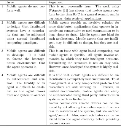
When adopting an agent view of the world, it becomes apparent that a single agent cannot do everything. We have many agents with different beliefs and capabilities that influence their decisions. The agents have to interact with each other to achieve their individual objectives and coordinate with other agents. The view of an agent system can be seen as in Figure 1.2. The agents communicate with each other using the Agent Commu-nication Language (ACL). An agent commuCommu-nication language consists of primitives (called performatives) that allow agents to communicate their beliefs,capabilitiesandcommitments
Initialize Mental state and capabilities. Define rules for
making new commitments
Update Mental State
Execute Commitments for
the current time
Representation of mental states and Capabilities Data
Control
Incoming Message
Outgoing Message
Figure 1.1: Generic Agent Interpreter[1]
• query another agent about the value of some proposition,
• inform an agent of some proposition and receive an acknowledgment (of belief and /or receipt),
• synchronize data with another agent about the value of some proposition, and
• ask an agent if it will undertake some action, and, if it is agreeable, to tell (command) it to do that action. The final communication will be the result of executing the action (if it succeeds or fails).
1.2
Service-Oriented Architectures
Environment
Sphere of visibility And influence
Figure 1.2: Canonical view of an agent-based system [7]
services are expected to be reusable and interoperable in different environments, the follow-ing characteristics are attributed to a SOA [2]:
• Technology neutral: Protocols, descriptions and discovery mechanisms should comply with widely accepted standards.
• Loosely coupled: They must not require knowledge, internal structures or conventions at the client or service side.
• Support location transparency: Services should have their definitions and location information stored in a repository such as UDDI and be accessible by a variety of clients that can locate and invoke services irrespective of their location.
The service-oriented approach is independent of specific programming languages or operating systems. It allows organizations to expose their core competencies over the Inter-net or a variety of Inter-networks including LAN, mobile ad-hoc Inter-networks, GPRS, and Bluetooth. Web services are the most promising technology based on service-oriented computing. This is because web services are composed of many services that are distributed over the network and are available via standard interfaces and protocols. Four common protocols that are used in web service-based SOC are
• Simple Object Access Protocol (SOAP): A platform-independent protocol for exchang-ing XML-based messages normally usexchang-ing HTTP/HTTPS.
• Web Service Description Language (WSDL): An XML-based protocol that allows web services to describe the capabilities, the interfaces, and addresses of end points.
• Universal Description, Discovery and Integration (UDDI): A platform-independent, XML-based registry for businesses to register their services on the Internet.
• Business Process Execution Language (BPEL): A protocol used to orchestrate ser-vices, i.e., discover and compose services.
In this thesis a SOA will be built to provide services that are not related to e-commerce. However, the services that are described in this thesis can be easily extended to operate as or with web services.
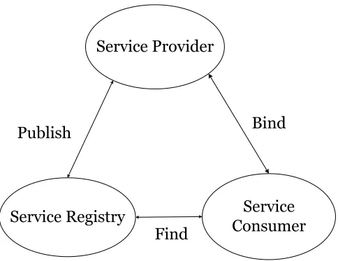
A simple service-oriented architecture is composed of producer (of services), con-sumer (of services) and a directory (of services). Optionally, many service-oriented technolo-gies also have a broker, which helps in building scalable and distributed directory services. A simple service-oriented architecture is based on three interactions: publishing a service, finding a service and binding to a service provider. Figure 1.3 illustrates a basic SOA architecture.
The basic SOA architecture does not capture the various facets of this vast field. A new extended SOA has been proposed by [8]. The components of this extended SOA are divided into three planes.
Service Registry ConsumerService
Publish Bind
Find
Figure 1.3: Basic service-oriented architecture
UMTS, GPRS, and Bluetooth etc. This layer describes basic interactions involving
description, publishing,finding and bindingof services.
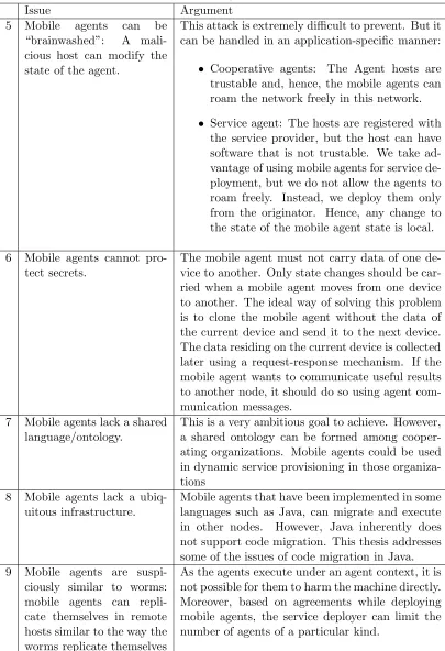
• Service composition: The middle plane defines roles and functionality for aggregation of multiple services into a single composite service. The steps of a service composition are as shown in Figure 1.4. The idea is that, based on a particular problem, services are chosen from a repository and among these services, some are provisioned to be used based on the domain knowledge/trust model. Finally, the services are invoked in a certain order as defined by the problem.
• Service management: The top plane defines mechanisms to monitor the health of systems that implement the services.
Apart from these, there are service characteristics that cut across all three planes. These include semantics, non-functional service properties and quality of service (QoS). Quality of service encompasses important functional and non-functional service quality attributes, such as performance metrics (response time, for instance), security attributes, (transactional) integrity, reliability, scalability, and availability [8].
Service Registry Domain Knowledge/Trust Model
Workflow-Selection Match-Making Provisioning Invocation
Success Repository/
Planner
Figure 1.4: Service Composition[6]
1.3
Mobile Agents
A mobile agent is an agent that can migrate from one machine to another, interact with other agents in that environment, and take new decisions based on that interaction. A mobile agent has the following characteristics and brings the following advantages to the table:
• It can roam the network, connect to different devices, discover new services in those devices and, hence, help in better service provisioning.
• It can interact with other agents in the system and arrive at new decisions faster than static agents that rely on message passing over the network, inducing delay.
• It can roam the network without a specific itinerary based on the intelligence obtained in the current environment and, hence, assimilate data in a manner that was not pos-sible in previous distributed computing paradigms. Mobile agent can choose different migration strategies depending on its task and current network conditions.
agents are not always resident in a system, which may potentially help in power conservation.
• It enables flexible service deployment on heterogeneous devices and on-the-fly code updates for the running services.
• It enables load balancing and fault tolerance for the service by replicating itself in new environments.
• It can monitor the health of the system and self heal the affected system based on intelligence acquired from the environment.
1.3.1 Mobile Agents as a Fluid SOA
The primary goal of a service-oriented architecture is to create a number of loosely coupled, reusable services. These services could then be dynamically assembled and re-assembled into any number of different applications based upon ever changing business requirements. Mobile agents provide a superior solution to building a SOA compared to the currently used distributed component object models that are based upon application servers. By deploying mobile agents from one node to another, we are introducing services close to the data, which improves execution time. Also, it increases the number of services available for provisioning.
1.4
Remote Data Collection and Analysis
particular problem. In addition, the traditional distributed algorithms solve a problem in the same manner every time, leaving less room for intelligent decisions. Apart from this, note that most distributed algorithms involve many interactions with the initiator, which makes them useless when the network is disconnected.
Consider a specific scenario of distributed data collection in a military opera-tion. Soldiers are equipped with devices that have various I/O capabilities like audio input/output, text input/output, video, image and other sensory input/outputs. These devices may also be equipped with advanced communication hardware like Wireless LAN (WLAN), General Packet Radio Service (GPRS), Bluetooth and Global Positioning System (GPS). These devices are needed to collect various kinds of data during runtime. Five major problems must be dealt with when using these devices:
• These devices have low battery and low CPU power.
• They are mobile and, hence, can lose connectivity with the base station.
• They need to collect diverse data; not all of it can be foreseen before hand.
• They can be damaged by physical impact and may also have unreliable firmware.
• They use various communication methods, have different GUI and, hence, we need interoperability.
Apart from this, there is one significant advantage of these devices. They are in the field for a long time and collect a lot of data. For this reason, the devices are valuable assets to the users as the devices themselves may provide intelligent suggestions to the user.
There could be many distributed computing paradigms that solve some of the above problems individually, but no paradigm solves all of the above problems. There has been no paradigm to solve the problem with intermittent connectivity and damageable hardware. A mobile agent solves the above problems in a very intuitive manner. We next discuss how it addresses each of the issues.
tivity can also consume battery power. Mo-bile agents can operate without network con-nectivity for long periods.
2. The devices are mobile and, hence, can lose connectivity with the base station.
Mobile agents can operate during network dis-connection. They can resume connection with a network at a later time and communicate with the base station.
3. The devices need to collect di-verse data, all of it cannot be foreseen before hand
Codes and queries can be dynamically up-loaded to the devices at run time. This gives a flexibility to mobile agents that can not be thought of in other paradigms.
4. The device can suffer physical damage and lose data.
Since mobile agents are capable of transport-ing the code with the state and data, it can be transported to another system (both proac-tive and reacproac-tive strategies can be applied). 5. The devices use many different
transports and GUI.
Since the agent code is generic, it can adapt to different environments and gain informa-tion about the environment and take decisions based on it.
a type of mobile agent called the itinerant agents. Itinerant mobile agents are programs, dispatched from a source computer, that roam among a predefined set of networked nodes until they accomplish their task. The approach taken in this thesis is to use Itinerant agents for remote data collection and service-oriented architecture for data analysis.
There are works similar to this in the areas of mobile agents, distributed objects, process migration, grid computing and service-oriented computing. Let us consider each of them in brief, and contrast them to this thesis work.
routes the mobile agent to other nodes. This work illustrates how to build a mobile agent architecture. However, this work does not include connectivity via wireless and does not consider connectivity with handheld devices. This thesis uses the concept of an itinerary from this paper and expands on it to include handheld devices and wireless connectivity. The work using D’Agents [11] also considers distributed information retrieval. This work is attractive as it considers many interesting facets in mobile agent computing. First, it discusses the improvement in retrieval time of documents compared to RPC, another tech-nology that competes with mobile agents. Second, the paper discusses how to plan an itinerary to traverse different nodes based on the probability of finding a document in a sys-tem. This probability is obtained by measuring some statistics of most common searches. Again, the work using D’Agents did not cover mobile phones and PDAs. There have been many other applications using mobile agents, such as those in distributed forensics, network management, mobile databases etc., but they all involve personal computers and servers.
JADE [13] is a Java agent deployment environment that is another popular mobile agent framework. JADE has been extended to support mobile phones with the addition of the LEAP[14] framework. JADE-LEAP (JADE powered by LEAP) has been used in some applications, but none of them have been deployed widely. The implementation in this thesis is built upon the ORMAC (Oak Ridge Mobile Agent community) that has been used in a variety of agent-based applications for the past ten years [18, 19, 20]. Moreover, JADE does not directly offer support for itinerant agents, which further complicates the software effort.
Distributed Objects (CORBA and DCOM): There are various distributed object-oriented client server platforms that have been commercially deployed and can also be used for distributed data collection. The main issue with using this technique is that it is built upon a client server type request-response model, which means the connection has to be maintained at all times during computation. This is not so suitable for remote data collec-tion operacollec-tion where intermittent non-connectivity is common. Apart from this, CORBA and DCOM do not offer code mobility, which means services cannot be dynamically de-ployed on those devices.
can migrate between similar devices. Migration is platform dependent. In a heterogeneous network of devices, process migration is not very useful, as the executable file formats of the devices may be incompatible.
Grid Computing: Grid computing [16] involves coordination, storage and network-ing of resources across dynamic and geographically dispersed organizations in a transparent way for users. What distinguishes grid computing from typical cluster computing systems is that grids tend to be more loosely coupled, heterogeneous, and geographically dispersed. In addition, while a computing grid may be dedicated to a specialized application, it is often constructed with the aid of general-purpose grid software libraries and middleware. Grid computing enables the creation of Virtual Organizations (VO) for sharing resources that are scattered across multiple geographically distributed organizations. Scheduling the accesses to resources is one of the main research areas in grid computing. A grid-based architecture is not a suitable paradigm for computation on mobile phones, as mobile phones do not have many I/O resources that can be used remotely and cannot take up computation for other nodes as they do not have computational power.
A new approach Mobile Agent + SOA:
Four main reasons to consider an architecture that integrates mobile agents with service-oriented architecture are:
• Mobile phones are good data collectors but poor compute devices. In addition, their battery power is precious. Hence, compute-intensive tasks must not be executed on the mobile device.
• Deployment of new services can be performed seamlessly using mobile agents.
• Even if the agent on the mobile phone could cooperate with other agents in the agent network, the performance of Java is significantly slower compared to its C counterpart in a high-performance application.
• By utilizing SOA to execute our compute intensive task, a whole new library of services can be used along with agents to solve specific problems.
1.5
Mobile Agents Criticism
Figure 1.5: Panoramic view of the system
1.6
System Overview
The high-level architecture of the system consists of two parts, the mobile agent system architecture and the service-oriented architecture. The mobile agent system is com-posed of a network of nodes on which the mobile agent can de deployed. These nodes can be mobile phones/PDAs, personal computers or servers. The mobile agent can roam freely on any of these nodes and communicate with other mobile agents and agents in the local system. In this mobile agent design, we consider the itinerant agents (mobile agents with an itinerary), that follow an itinerary in order to traverse the nodes in the network but can decide to take certain run-time decisions based on the environment.
PS3), in a platform and language neutral manner. Moreover, we also demonstrate how ser-vices can be described, advertised and composed. Even though the mobile agent platform can be made platform-independent, it is difficult to make it language-independent. Not all languages are suitable for all services. Having a SOA-based architecture provides us both with platform and language neutrality. Fig 1.5shows the high-level view of the system. The system consists of many devices that can be interconnecting with each other by different transport mechanisms.
1.7
The Main Contributions
This thesis has two main contributions
• Design and implementation of a intelligent communication middleware (mobile agent) that saves bandwidth, power, CPU on the mobile device, while efficiently collecting the relevant data from remote devices. The thesis discusses the protocol of operation of an itinerant agent framework, and the challenges of implementing it in J2ME. The author also describes the method of integrating the mobile agent with a service-oriented architecture using platform neutral protocols such as XML-RPC
• Implementation of high-performance kernels on Cell broadband engine, for efficient analysis of data. The thesis measures the performance speedup obtained for solving certain non-regular scientific kernels and attempts to provide reasons for the speedup.
1.8
Thesis Hypothesis
Table 1.2: Mobile Agent Issues
Issue Argument
1 Mobile agents do not per-form well.
This is not necessarily true. The work using D’Agents [11] has shown that mobile agents per-form better than RPC in a general scenario and in particular, data retrieval applications.
2 Mobile agents are difficult to design: Most distributed systems have a complex-ity that can be addressed using normal distributed computing paradigms.
Mobile agents provide an intuitive solution for some distributed applications that operate in in-termittent connectivity or need computation to be done closer to data. Mobile agents are ideal for such applications. Mobile agents that are intelli-gent may be difficult to design, but they are scal-able.
3 Mobile agents are difficult to develop: It is hard to foresee the heteroge-neous environments that the agent operates in.
This is an issue with agent-based computing, not mobile agents in specific. All agents involve se-mantics by which they take intelligent decisions. Formulating the semantics is not an easy task. However, once developed the system is highly scal-able.
4 Mobile agents are difficult to authenticate and con-trol: The Identity of an agent is difficult to estab-lish as the agent moves from one system to another
It is true that mobile agents are difficult to au-thenticate in a completely new environment. Trust management is a very complicated problem that researchers are still working on. However, in trusted environments, mobile agents can easily be authenticated using third party authentication systems, such as Kerberos.
Table 1.3: Mobile Agent Issues... continued
Issue Argument
5 Mobile agents can be
“brainwashed”: A mali-cious host can modify the state of the agent.
This attack is extremely difficult to prevent. But it can be handled in an application-specific manner:
• Cooperative agents: The Agent hosts are trustable and, hence, the mobile agents can roam the network freely in this network.
• Service agent: The hosts are registered with the service provider, but the host can have software that is not trustable. We take ad-vantage of using mobile agents for service de-ployment, but we do not allow the agents to roam freely. Instead, we deploy them only from the originator. Hence, any change to the state of the mobile agent state is local.
6 Mobile agents cannot pro-tect secrets.
The mobile agent must not carry data of one de-vice to another. Only state changes should be car-ried when a mobile agent moves from one device to another. The ideal way of solving this problem is to clone the mobile agent without the data of the current device and send it to the next device. The data residing on the current device is collected later using a request-response mechanism. If the mobile agent wants to communicate useful results to another node, it should do so using agent com-munication messages.
7 Mobile agents lack a shared language/ontology.
This is a very ambitious goal to achieve. However, a shared ontology can be formed among cooper-ating organizations. Mobile agents could be used in dynamic service provisioning in those organiza-tions
8 Mobile agents lack a ubiq-uitous infrastructure.
Mobile agents that have been implemented in some languages such as Java, can migrate and execute in other nodes. However, Java inherently does not support code migration. This thesis addresses some of the issues of code migration in Java. 9 Mobile agents are
suspi-ciously similar to worms: mobile agents can repli-cate themselves in remote hosts similar to the way the worms replicate themselves
Chapter 2
Design and Implementation
This chapter describes an abstract framework for itinerant mobile agents that can be used to implement secure, remote applications in large intranets and public networks such as the Internet. Itinerant mobile agents are programs dispatched from a source computer that roam among a set of networked nodes until they accomplish their task. An additional feature of itinerant agents is their ability to migrate from node to node, perhaps seeking one that can help with the user’s task or perhaps collecting information from all of them. A major focus of this work is the design of a middleware to enable the agents to discover other nodes, move from one node to another and communicate with other agents in the system.
We start by describing the network in which the mobile agent runs, i.e., description of various nodes in the system, followed by design of the mobile agent architecture, followed by the protocol of operation for the Itinerant mobile agents.
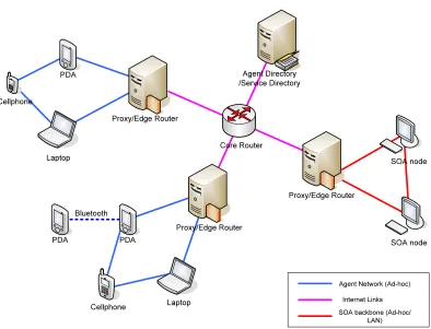
2.0.1 Description of the Network
Agent Network (Ad-hoc) Internet Links SOA backbone (Ad-hoc/
LAN)
Bluetooth
Agent Directory /Service Directory
Proxy/Edge Router PDA
Laptop Cellphone
Core Router
Proxy/Edge Router
Proxy/Edge Router PDA
PDA
Cellphone Laptop
SOA node SOA node
Figure 2.1: Transport Level Diagram
proxy are invisible to the outside world, but they can see the nodes that have a public IP address. In order to connect to these devices, messages must be sent to the proxy, which will forward the messages to the devices. There are special sockets called JXTA (Juxtapose) sockets in Java for peer-to-peer systems. While using JXTA sockets, the nodes that do not have a public IP address rely on super peers to forward the messages to them. We are, however, not going to consider using JXTA sockets in our thesis.
Apart from this, we may also have DHCP issues. Every time a node behind the DHCP reconnects to the network, it may have a different IP address that it must notify the agent directory and the proxy. The agents must be addressed by an agent-id. All communications must be done using this identifier because the agent may not have the same IP address and may not be associated with same proxy all the time. When an agent enters a system, the agent directory and the proxy associated with that node need to be notified to update their tables.
a public IP address.
Service Directory It contains the descriptions of various services in a SOA
accessible via the In-ternet
Proxy/Edge Router This device has a public IP address. It can also act as
a NAT/DHCP server. A
proxy has a shallow router that maintains a mapping be-tween agent-id and agent ad-dress.
accessible via the In-ternet
Core Router This router is capable of con-necting different nodes in the Internet.
accessible via the In-ternet
SOA node This node hosts services that
can be used by other nodes.
LAN/WLAN/Ad-hoc
Personal computer /Laptop
This device hosts the J2SE agent execution environment
LAN/WLAN/Ad-hoc
PDA This device hosts J2ME (CDC
profile) agent execution envi-ronment.
LAN/WLAN/Ad-hoc/Bluetooth
Cellphone This device hosts the J2ME
(CLDC profile) agent execu-tion environment.
LAN/WLAN/Ad-hoc/Bluetooth/GPRS
GPRS, WLAN (Access point and Ad hoc), UpNp, to name a few. Apart from this, there are a number of transport protocols that can be used for connection, namely stream (TCP), datagram (UDP), HTTP (Even though HTTP is not a transport protocol, the devices han-dle HTTP request/responses in a different manner than stream/datagram sockets. Many operators prefer to block datagram connections to the mobile phones), SMTP (same expla-nation as HTTP). Bluetooth, by itself, cannot be used to connect to the network. However, it can connect via another device in the network. Therefore, the handheld devices can be connected in a variety of ways, so it is necessary for the Agent Host on the device to indicate how it would like to get connected when it starts up.
2.0.2 Agent Architecture Design of Ubimac
Agent UI
Message Authentication Layer
Transport Providers Agent Host
Roles Role Specific Context
RMI
Datagram J2SE Datagram J2ME
TCP HTTP
Application Specific UI
Figure 2.2: Agent Architecture
The agent architecture designed as a part of this thesis is called Ubimac (Ubiqui-tous Mobile Agent Community) .The design of Ubimac is as illustrated in the Figure 2.2. There are three layers: transport layer, core components, and application-specific UI. The application-specific UI is not a part of Ubimac, the user is free to register his own UI and have agent-specific functionality here. The users can also register their own transport layer. Right now, Ubimac supports two transports, the DatagramTransport J2SE and Datagram-Transport J2ME, but the user can add other transports such as RMI and TCP if these transports supports the target devices.
Design Motivations: The design of Ubimac considered the following important factors:
• Modularity: Modularity addresses the separation of concerns and supports quick
is called a transport provider. The user of Ubimac can register his choice of transport provider. In the same lines, the Agent UI can be implemented separately for different devices.
• Open/closed principle: The open/closed principle is a popular concept in software
engineering. This means that certain components (for e.g., UI and Transport) must be open while keeping the interfaces to the core components closed because accidental changes to core components can result in unpredictable results.
• Enable greater code reuse via conditional compilation: To facilitate greater code reuse
across platforms, Ubimac considers having one code for all platforms and conditionally add/remove certain blocks (which use a platform-specific API) from the code by using preprocessor directives.
2.0.3 Security Considerations
The security goals of the agent system can be as follows:
• Protect the system: agent must not be able execute code that is harmful to the machine ;
• Protect other agents: execution of one agent must not disturb other agents ;
• Protect a group of machines: The agent must not consume infinite resources ;
• Protect the agent: A malicious node should not be able to modify the state of the agent. This is impossible to achieve on a malicious node, but once the agent returns to a trusted node, the state must be reverted to a harmless state.
The system is protected in three ways.
run through a preverifier designed specifically for Ubimac. This preverifier checks if the class uses some I/O classes directly. The preverifier can be written using the ASM library[17], which allows you to look through the bytecode for instances of specific classes. On finding an I/O class in the field section or inside a method, precompilation is deemed to have failed.
• Controlled execution of instructions: The agents run in their own context and, hence, cannot influence the execution of other agents. Access to resources is controlled via the context. Whenever the agent is created/moved, its agent host must communicate with the remote agent host and request a specific set of roles (such as file accessor, socket writer, data generator etc). Based on the agreed set of roles, the remote agent host creates a context specific to the agent. This context allows accesses to particular resource types based on the roles the agent is playing.
• Role-based access management: Some components of the system (such as the locator daemon and agent host) are trustworthy whereas the agents that come from the network may not be trustable. Trustworthy resources get full access to the system whereas agents must execute within their own context and any exceptions caught while running the agent should not affect the execution of other agents.
Message-authentication layer: As in Figure 2.2, the message-authentication layer applies to all components of the system, i.e., agent host, agents, locator daemon (program at the agent directory) and locator client. When two nodes talk for the first time, a authentication session is established between them. The responsibility of doing this authentication lies with the agent hosts. This establishes a private key with which the messages are encrypted at the sender side and decrypted at the receiver side. The method of doing this authentication is by using a trusted third party authentication system, such as Kerberos. This security feature has been widely explored in research communities, and has been successfully deployed in many systems, hence, it is less exposed in this thesis.
comprised of class name and a random number generated by the agent directory. The proxy address is the public IP address of the proxy to which the agent is connected. If the agent moves to a different location, then the proxy address will also need to be updated. The proxy address is needed for the sake of bi-directional connectivity. As most nodes either are behind NAT or receive a dynamic DHCP address, they are not visible to the outside world. However, they can access nodes with public IP via the proxy and can also receive messages from the outside world via the proxy that maintains a table of agent-ID to local -IP address mapping.
The agent has an itinerary, which consists of a list of nodes that needs to be accessed. If a node is reachable, then the node is marked as covered, and the code (with the modified itinerary) is sent to next node. If the node is not reachable, then the node is marked as uncovered, and the next node in the itinerary is checked for connectivity. The itinerary can be modified dynamically if new nodes are discovered and are reachable via the current node. This typically happens if the node receives connections via other means of communication, such as the Bluetooth.
The agent can have some roles, such as file accessor, file writer, UI accessor etc., based on which it can be decided if the agent can run on that device. If it can run, then a specific agent context is created at the agent host permitting those accesses. The agent can have certain attributes through which it can be queried in the agent directory. It can relate to agent functionality, capabilities and beliefs. Also, collection of these attributes can be used to infer new decisions.
The agent has a main execute() function that is invoked on its arrival at an agent host after its credentials are checked. Apart from these, there are functions in the agent that aid the communication. The agent can carry other application-specific functions.
2.0.5 Agent Host Structure
Figure 2.3: Itinerant Agent Structure
• Agent Context Manager: When an agent arrives at an agent host, the roles assigned to
the agent are checked to decide if this device can satisfy them. If so, then a specific agent context is created that allows resource access required by that role. Agents must not be allowed direct access to any resource; the agent will send a message to the context that accesses the resource on the behalf of the agent. The agent context can check any suspicious activity of the agent. This may slow down the processing, but is very important from the point of view of security.
• Resource Manager: There can be many agents running in the system at the same
time, and they may request the same resource. The resource manager can arbitrate the requests to the resource. Deadlocks can be avoided by mandating the agents to request all resources it needs before starting and relinquishing the same on exit.
• Mobility Manager: As the devices are mobile, the devices can be associated with
different networks. The way the device is associated with a new network is out of the scope of this thesis. This can be done either manually or automatically. The agent host must track this change and respond. The agent host must notify the agent directory of the current proxy it is associated with (if it is associated with a proxy) of the new IP address. This is necessary as any node that wants to communicate with agent host/agents on this device will need to contact it via the new address.
• Authentication Manager: When two nodes talk for the first time, an authentication
which messages received from different agent systems can be mapped to some other well-known messages (if possible), or to at least partially understand the message and derive some facts that can later be used to infer some decisions.
2.0.6 Design of Agent Directory
The agent directory must be available on the Internet so that any node can access it. The agent directory consists of agent descriptions and host descriptions. Sometimes, a host can be contacted via more than one transport method, say via GPRS and WLAN. The host description provides all the addresses associated with the node and transport-specific attributes. The agent description gives the agent name, host address, and agent attributes. The entries for host and agent are:
Directory Entry for Host A:
Host-Name: A Host-Locator:
Transport-Type: HTTP
Proxy-Address:http://sys01.csc.ncsu.edu:8080
Local-Address:http://192.168.0.11:8080
Transport-Specific-Property:none
Transport-Type: Datagram
Proxy-Address:datagram://sys08.csc.ncsu.edu:8005
Local-Address:http://192.168.2.11:8005
Transport-Specific-Property:none
Host-Attributes:
Device-Type:PDA
Java-Profile:CDC
Has-File-Support:Yes
Has-Bluetooth:Yes
Using the host information from the agent directory, other nodes can make an informed decision whether the agent needs to move to that device. If a particular service needs to access the file but the device has a Java installation that does not support file access, then there is no point in sending the agent to that device.
Directory Entry for Agent X:
Agent-ID:edu.ncsu.ubimac.agent.DataCollector@768768
Host-Name: A
Agent-Attributes:
Type: Data-Collector
Roles: FileAccessor, FileWriter, UIAccessor
The program running on the agent directory is called a locator daemon that listens on a dedicated port number. Every host that wants to communicate with the locator daemon starts a locator client that is common to all agents running in the system.
2.0.7 Different Types of Agents.
• Meta-agent: A meta-agent is an agent that creates other agents. The agent does not run on the device itself but is sent to other devices. The meta-agent is also a part of the service-oriented architecture. It offers certain services (in this case the data collection service) to the world. In providing this service, it utilizes the capability of other agents in the network.
• Data collector: This agent identifies the context-specific information and stores it in the file system if file writing is allowed, or it carries the information to another node if file writing is not allowed. Once the data collection operation is completed, the data collector agent moves to the next node in the itinerary. If the next node does not respond, it marks the node as non-responsive and moves to another node in the itinerary. Later, if the data is requested by another agent, it either accepts or rejects to send the collected data to the device (based on its credentials).
• Proxy agent: The proxy agent is a static agent installed on a proxy device. The proxy agent enables a bidirectional communication with the agents behind a NAT and other devices in the Internet. A proxy agent has a mapping of host names of all agents in its network and their local IP addresses. When it gets a message from the outside network for a device in the local network, it forwards the message to it. It also forwards all the messages sent by a device in the local network to the outside world.
• Relay agent: A relay agent is an agent that forwards messages for another device on its behalf. This agent is helps to connect to devices via Bluetooth.
• Service agent: A service agent connects the mobile agent to the SOA. It receives the information from the mobile agent, creates a XML-RPC request and invokes a data analysis service on a SOA node.
2.1
Protocols
The Figure 2.4 shows the sequence diagram of the normal operation of data col-lection and analysis.
2.1.1 Mobile Agent Creation
On the creation of a mobile agent, the following steps are undertaken:
• Create an agent context based on the roles requested and allocated for the agent ;
• Set the agent state to AGENT CREATED ;
• Register the agent with the agent directory ;
• Register the agent with the proxy ;
It should store the data and expect it to get connected another node in the near future. The mobility manager in the agent host will notify all the agents in the system when the node gets associated with a new network. If this happens, the mobile agent should try to connect to other nodes in the itinerary. From time to time, the originator of the agent tries to handle exceptions and this scenario in section 2.1.5.
If a mobile agent finds that another node is reachable and has the same proxy as itself, then it does not need to do authentication. It marks the next node in the itinerary as covered, creates a clone of itself and jumps to the next node. On moving to the next node, it need not carry the data with it, but it needs to carry the itinerary with it.
If there is already an agent of the same kind running there, the agent terminates without doing anything. If there is no agent of the same kind running there, then the same steps as mobile agent creation are followed. If the agent is migrating to an un-trusted domain, it should request the agent host to start an authentication session with the remote node. If the authentication session succeeds, then the agent moves to the new node. If the authentication fails, then the node is marked as uncovered, and the agent migrates to the next node in the itinerary. If no node can be authenticated from this node, the the mobile agent takes no action. From time to time, the originator of the agent tries to handle exceptions and this scenario will be covered in section 2.1.5.
2.1.3 Mobile Agent Communication
As Shoham [1] put it, a computation in an agent-based system consists of these agents informing, requesting, offering, accepting, rejecting, competing, and assisting one another. A mobile agent system differs from conventional agent-based system where there is extensive cooperation among agents. The problems mobile agent computing addresses are mostly those that involve disconnected operation and asynchronous responses to requests. Therefore, this thesis mainly restricts agent communication to:
“comple-tion of activity”, “unable to authenticate”, “aborted uncondi“comple-tionally”, “register” and “unregister” (to proxy agent and locator daemon).
• Request: An agent can request another agent to perform some activity for it, e.g., return the collected data to a destination or relay a message on its behalf etc.
• Accept: Response to the requests can be an accept or a reject. In case of an accept, the response contains some data specific to the request.
• Reject: In case of a reject, the reason for reject will be specified.
2.1.4 Mobile Agent Departure
Usually, after the data collection, the mobile agent is still resident in the system. In order to move to another node, it creates a clone. The mobile agent departs from a system when it receives a inform message containing “completion of activity” from the originator of the mobile agent. On departure, the agent context that is used to run the agent is destroyed, and the agent sends an inform message containing “deregister” to the proxy agent and the locator daemon.
2.1.5 Exception Handling
The following exceptions may occur in the system:
case, the agents itinerary is still marked as uncovered. At a later time, other agents will attempt to connect to it. Each time the host is unreachable, a note will be made recording the number of retries. If the number of retries is above a threshold, the other agents will stop trying to connect to it, and the data collected by that node is lost.
2.2
J2ME Technology
Mobile phone applications can be written using two development platforms [35]:
• Native code: Native code development is usually done in C or C++. Native code is useful when one needs the absolute maximum performance from a system or one needs low-level access to the hardware. Native code is processor dependent. Hence, deployment of the code has to be processor and compiler dependent. Usually, the native code developers manage their own memory, provide their own libraries, and have application-specific security mechanisms.
• Managed code: Managed code development is usually performed using the J2ME or the .NET compact frameworks. These platforms run the code in a managed run-time environments that manage memory usage, security, and use a rich set of libraries and components that are available for all processor platforms. Managed code development right now dominates the mobile phone applications as the focus of most mobile ap-plications is not to be compute intensive but rather to be interoperable with a wide range of devices.
provides users with a working environment that mirrors what users are used to seeing on PCs. Due to the fact that the majority of companies’ applications are in a Microsoft environment, back end interoperability is easier. Both J2ME and .NET have a great IDE and support emulators to ease development and installation of the code. The main difference between J2ME and .NET however, is that J2ME supports a wider range of devices whereas .NET is supported by Pocket PCs under a Windows OS. In order to be interoperable with a maximum number of devices, this thesis chooses Java as the core technology.
Figure 2.5: Java Editions and their target markets
limited capability (e.g., memory size, CPU power, system design, availability of keypad etc.), the J2ME consists of 3 layers (virtual machine, configuration and profile) that can be customized to the specific hardware needs of the used mobile platform.
2.2.1 J2ME Configurations and Profiles
A configuration consists of a virtual machine that implements some portion of the Java language, virtual machine specifications, and a minimal supporting set of class libraries and APIs. These libraries are built for all devices of a particular segment. Profiles are built on top of configurations to support device-specific features, such as networking and UIs. Each valid combination of configuration and profile targets a specific type of device.
• Connected Limited Device Configuration (CLDC): addresses devices with a significant resource limitations, such as cell phones and pagers.
• Connected Device Configuration (CDC): addresses devices with a higher set of physical resources, like PDAs or set top boxes.
The list of devices that support J2ME and their Java configuration and supported profiles can be obtained from [39].The main profiles that are used in J2ME are listed in the Table 2.2.
CDC is backward compatible with Java 1.2. It has support for more classes and operations than CLDC. CLDC has the following limitations, that are not present in the CDC environment:
• No floating point support,
• No serialization and reflection: This means that we cannot transmit objects over the network.
Table 2.2: Java Profiles
Profile Description
MIDP This profile is used with CLDC. The MIDP
specification addresses issues, such as user in-terface, persistence storage, networking, and application life cycle on CLDC devices. The programs written in MIDP are called Midlets. Foundation Profile (JSR-219) This profile is used with CDC. It provides ap-plication supported classes like network and I/O support without a GUI API
Personal Basis Profile (JSR-217)
This profile is used with CDC. It pro-vides a standards-based GUI framework with lightweight components.
Personal Profile (JSR-216) This profile is used with CDC. It provides an AWT-based GUI toolkit. It support the de-velopment of applets.
File Connection (JSR 75) This is an optional package used with CLDC configuration. It gives access to the local file systems on devices like PDAs. It allows read and/or write access to the file system of the PDA.
The Remote Method Invoca-tion (RMI) OpInvoca-tional Package (JSR-66)
It provides a subset of the J2SE RMI API for networked devices based on Java technology.
The Java Database Connectiv-ity (JDBC) Optional Package (JSR-169)
• Threading features. CLDC provides threads, but it does not allow the creation of a daemon thread (a thread that is automatically terminated when all non-daemon threads in the VM terminate) or thread groups.
• Java Native Interface. CLDC does not provide the J2SE JNI feature, which allows native code to be called from Java classes.
2.2.2 J2ME Development Environment
The mobile agent code was tested on three JVMs NSICom CreME JVM (CDC), Esmertec Jbed (CLDC 1.1) and Symbian CLDC (CLDC 1.1). There are various tools that are available for J2ME development. Table 2.3 summarizes the various development tools that are used for the development of J2ME code.
2.3
Implementation of Mobile agents
There are some unique challenges to developing mobile agents on mobile phones, i.e., supporting multiple devices, developing a serialization framework and writing Midlets.
Serialization Framework: As discussed above, one of the main hurdles to deploying mobile agents on mobile phones is absence of a serialization framework (both in CDC and CLDC), which prompted the author to use third-party libraries, such as J2ME Polish to support serializable code. With some additional effort, even the ASM library can be used for serialization.
Table 2.3: J2ME Development Environment
Tool Description
Eclipse ME Eclipse ME is an Eclipse plugin to help de-velop J2ME MIDlets. It helps various ac-tivities, such as compilation, running build scripts, signing midlets and deployment of jar files.
Netbeans Mo-bility Pack
Netbeans has an IDE for CDC code develop-ment. It is a CDC counterpart of Eclipse ME Sun Wireless
Toolkit
A toolbox for developing Wireless applica-tions that is mainly used as a cell phone em-ulator
Apache Ant Ant scripts are counterparts of Make in Java. ObjectWeb
ASM
ASM is an all-purpose Java byte code manipu-lation and analysis framework. It can be used to modify existing classes or dynamically gen-erate classes, directly in binary form.
Antenna Antenna provides a set of Ant tasks suitable for developing wireless Java applications tar-geted at the Mobile Information Device Pro-file (MIDP). Antenna is mainly used to pre-compile Java code for specific devices.
loaded using byte code. This feature is absent in the CLDC version of J2ME. However, CDC versions have support for dynamic class loading. In order to load classes dynamically, custom class loader is required that reads serialized object (byte code) from the network and loads a new class.
2.4
Interfacing with a Service-Oriented Architecture
As discussed in the previous sections, data computation can be a performance-intensive task that may not be done using Java. C is better than Java in compute performance-intensive tasks. In addition, special architectures such as the Cell Broadband Engine are well suited for executing certain algorithms. A mechanism is required to call the services offered by third party software in a platform neutral manner. A service-oriented Architecture, which uses platform and language neutral protocols for communication, publishing and composition, is an ideal choice to accomplish this work. This thesis considers integration of a Java-based agent platform on a Windows machine on the x86 platform with C-based data analysis programs on Linux running on Cell Broadband Engine platform.
Remote Procedure Call (RPC) is one of the ideal ways of invoking a service on a remote machine. RPC is attractive as it allows the service interface to be published for any system to invoke it. RPC has been implemented by various technologies. Among those, CORBA, DCOM, SOAP and XML-RPC have been deployed. CORBA and DCOM have been around for more than ten years. They have been widely deployed in distributed object environments. However, with the emergence of web services, two new protocols, XML-RPC and SOAP, are being adopted by many companies as a promising technology. Here is a brief description of the messaging technologies
together. CORBA uses an interface definition language (IDL) to specify the interfaces that objects will present to the outside world. The CORBA specification dictates that there shall be an Object Request Broker (ORB) that understands the IDL, through which the application interacts with other objects.
• DCOM: DCOM is similar to CORBA and is developed by Microsoft.
• XML-RPC: XML-RPC is a specification for making RPC calls using HTTP as the transport and XML as the encoding scheme. The greatest advantage of XML-RPC is its simplicity. There is support for simple data types, but it does not allow the user to define complex data types. In addition, XML-RPC does not have names for the parameters.
• SOAP: SOAP was built as an extension to XML-RPC. SOAP’s greatest feature is its ability to step past XML-RPC’s limitations, build complex message and customize every portion of the message, e.g., providing names for parameters. This ability to customize allows developers to describe exactly what they want within their message. The downside of this is that the more you customize a message, the more work it will take to make a foreign system do anything beyond simply parsing it.
2.4.1 Comparison of Messaging Technologies
A performance study of various messaging technologies was done in [43]. Table 2.4 summarizes the results from that work. It can be seen that the SOAP and XML-RPC messages are just over 14 times as large as the binary CORBA messages. In addition, as you can see from the test where you sent 5,000 integers to the server, SOAP and XML-RPC took 882 and 66 times longer than CORBA on the same machine, respectively. Although CORBA has the best performance, there are many downsides to it [44]:
• CORBA is too complex : There is a steep learning curve in order to program in CORBA.
Table 2.4: Comparison of various Messaging Technologies
Raw Sockets CORBA
XML-RPC
SOAP
Connect time (sec) 0.0022 0.00073 0.0070 0.0006
Time to send string of 21,000 characters (sec)
0.0014 0.0046 0.0827 0.2942
Time to receive string of 22,000 characters (sec)
0.0014 0.0022 0.0502 0.2793
Time to send 5,000 integers (sec)
6.74 1.52 100.33 1,324.29
Client lines of code (bytes)
57 37 29 32
Server lines of code (bytes)
25 18 17 10
Actual message size sending 1,000 char-acters (bytes)
2,279 2,090 4,026 4,705
Actual message size sending 100 inte-gers (bytes)
Figure 2.6: Interfacing Mobile Agents with SOA
• IIOP (CORBA’s transport protocol) does not work through firewalls or proxy web servers : CORBA’s transport protocol the IIOP is not allowed through many firewalls, as it is not recognized as a protocol, or connections to the requested port are denied.
• Readability: Human readability is considered by many as important for faster devel-opment of code.
One of the main reasons of choosing an XML-HTTP-based RPC is that most webservers are open to HTTP requests. SOAP or XML-RPC requests and responses can be tunneled via HTTP. Suppose we decide to use an XML-based RPC, we have a choice of using SOAP, which is a W3 standard. This thesis considers using XML-RPC as the messaging technology. The main reasons for doing so are:
• It is very simple to understand and implement;
• Any application written in XML-RPC can be easily ported to SOAP.
2.4.2 Integration with SOA Using XML-RPC
Chapter 3
High Performance Kernels on the
Cell Processor
3.1
Cell Broadband Engine Architecture
The Cell Broadband Engine (CBE) architecture designed by a partnership of Sony, Toshiba and IBM (STI) to be the heart of Sony’s recently released PlayStation3 gaming system among other consumer devices. The Cell architecture takes a radical departure from conventional multiprocessor or multi-core architectures. Instead of using identical cooper-ating commodity processors, it uses a conventional high-performance Power PC core, the Power processing element (PPE), that controls eight simple SIMD cores called synergistic processing elements (SPEs), where each SPE contains a synergistic processing unit (SPU), a local memory, and a memory flow controller.
Element Interconnect Bus
DMA Cont
LS (256KB) SPE4 Dual Threaded, VMX
L1
(32KB) (512KB)L2
Memory Interface Controller (MIC)
IO Interface Controller
IO DMA Cont
LS (256KB) SPE5
DMA Cont
LS (256KB) SPE6
DMA Cont
LS (256KB) SPE7
Figure 3.1: Cell Architecture
store instructions that move data between main memory and a private register file, the contents of which may be cached. The SPEs, in contrast, access main memory with direct memory access (DMA) commands that move data and instructions between main memory and a private local memory called a local store or local storage (LS). An overview of Cell architecture is provided in Figure 3.1.
3.1.1 Scaling the Performance-Limiting Walls
Traditional processors have reached a point where greater investment is not yield-ing optimal performance gains. The Cell Broadband Engine overcomes three important limitations of contemporary microprocessor performance: power consumption, memory uti-lization, and processor frequency[23].
Power Wall Increasingly, microprocessor performance is limited by achievable power dissipation rather than by the number of available integrated-circuit resources. One way to increase power efficiency is to differentiate between:
• processors optimized to run an operating system and control-intensive code, and
The Cell Broadband Engine does this by providing a general-purpose PPE to run the operating system and other control-plane code, while eight specialized SPEs serve computing data-rich (data-plane) applications.
Memory Wall Currently, the program performance is dominated by the activity of mov-ing data between main memory (the virtual-address space that includes main memory) and the processor. The Cell Broadband Engine’s SPEs use two mechanisms to deal with long main memory latencies:
• a 3-level memory structure (main memory, local stores in each SPE, and large register files in each SPE), and
• asynchronous DMA transfers between main memory and local stores.
These features allow programmers to schedule simultaneous data and code transfers to cover long latencies effectively. Because of this organization, the Cell Broadband Engine can usefully support 128 simultaneous transfers between the eight SPE local stores and main memory. This surpasses the number of simultaneous transfers on conventional processors by a factor of almost twenty.
Frequency Wall Conventional processors require increasingly deeper instruction pipelines to achieve higher operating frequencies. Cell BE follows a different strategy:
• The PPE achieves efficiency primarily by executing two threads simultaneously rather than by optimizing single-thread performance.
• An SPE achieves efficiency by using a large register file, which supports many simulta-neous in-process instructions without the overhead of register-renaming or out-of-order processing.
3.2
Cell BE Architecture Elements
primarily for control processing, running operating systems, managing system resources, and managing SPE threads. It can run existing PowerPC architecture software and is well-suited to execute system-control code. The instruction set for the PPE is an extended version of the PowerPC instruction set. It includes the vector/SIMD multimedia extensions and associated C/C++ intrinsic extensions.
The PPE hardware supports two simultaneous threads of execution. All archi-tected and special- purpose registers are duplicated, except those that deal with system-level resources, such as logical partitions, memory, and thread-control . Most non-architected resources, such as caches and queues, are shared by both threads, except in cases where the resource is small or offers a critical performance improvement to multithreaded applications. Because of this duplication of state, the PPE can be viewed as a 2-way multiprocessor with shared data flow. The two hardware threads appear to software as two independent logical processors.
3.2.2 Synergistic Processing Elements
The eight identical SPEs are single-instruction, multiple-data (SIMD) processor el-ements that are optimized for data-rich operations allocated to them by the PPE. Each SPE contains a RISC core, 256KB software-controlled LS for instructions and data, and a 128-bit, 128-entry unified register file. The SPEs support a special SIMD instruction set—the Synergistic Processor Unit Instruction Set Architecture—and a unique set of commands for managing DMA transfers, interprocessor messaging and control. SPE DMA transfers access main memory using PowerPC effective addresses. The SPEs are not intended to run an operating system. The SPU is an in order processor with two instruction pipelines, referred to as the even and odd pipelines. The floating and fixed- point units are on the even pipeline, and the rest of the functional units are on the odd pipeline. Each SPU can issue and complete up to two instructions per cycle, one per pipeline.
Table 3.1: Communication mechanisms Mechanism Description
1. DMA transfers Used to move data and instructions between main memory and an LS. SPEs rely on asyn-chronous DMA transfers to hide memory la-tency and transfer overhead by moving infor-mation in parallel with synergistic processor unit (SPU) computation.
2. Mailboxes Used for control communication between an SPE and the PPE or other devices. Mailboxes hold 32-bit messages. Each SPE has two mail-boxes for sending messages and one mailbox for receiving messages.
3. Signal notifica-tion
Used for control communication from the PPE or other devices. Signal notification (also called signaling) uses 32-bit registers that can be configured for one-sender-to-one-receiver signalling or many-senders-to-one-receiver signalling.
instructions executed by the SPU can only access the LS. SPU software uses LS addresses (not main memory effective addresses) to do this. Each SPE’s memory flow controller (MFC) contains a DMA controller. DMA transfer requests contain both an LS address and an effective address, thereby facilitating transfers between the domains. Data transfers between an SPE’s LS and main memory are performed by the associated SPE, or by the PPE or by another SPE, using the DMA controller in the MFC associated with the LS.
3.2.3 Element Interconnect Bus
are implemented and controlled by the SPE’s memory flow controller (MFC). The three communication mechanisms are listed in Table 3.1
One of the functions of an MFC is to act as a specialized co-processor for its associated SPU. The MFC has the ability to execute operations from its command set, and it executes them autonomously. When possible and beneficial, the MFC will execute commands out-of-order.
DMA Transfers DMA commands initiate transfer data between the LS and main mem-ory. Main memory is addressed by an effective address (EA) operand in a DMA command. The LS is addressed by the local store address (LSA) operand in a DMA command. The size of a single DMA transfer is limited to 16 KB.
Each MFC can also autonomously manage a sequence of DMA transfers in response to a DMA list command from its associated SPU (but not from the PPE or other SPEs). Each DMA command is tagged with a tag group ID that allows software to check or wait on the completion of commands in a particular tag group. The MFCs support naturally aligned DMA transfer sizes of 1, 2, 4, or 8 bytes and multiples of 16 bytes with a maximum transfer size of 16 KB per DMA transfer. DMA list commands can initiate up to 2048 such DMA transfers. Peak transfer performance is achieved if both the effective addresses and the LS addresses are 128-byte aligned and the size of the transfer is an even multiple of 128 bytes.
length, such as buffer completion flags or program status. In fact, they can be used for any short data transfer purpose, such as sending of memory addresses, function parameters and command parameters. Mailboxes are useful, for example, when the SPE places computa-tional results in main storage via DMA. After requesting the DMA transfer, the SPE waits for the DMA transfer to complete and then writes to an outbound mailbox to notify the PPE that its computation is complete. If the SPE sends a mailbox message after waiting for a DMA transfer to complete, this ensures only that the SPE’s LS buffers are available for reuse.
Signals The PPE, other SPEs, and other devices use the signal notification registers to send information, such as a buffer-completion synchronization flag, to an SPE. An SPE has two 32-bit signal-notification registers, each of which has a corresponding memory mapped input output (MMIO) register that can be written with signal-notification data. The PPE sends a signal-notification message to the SPE by writing to a MMIO register in the SPE’s MFC. An SPE can also send a signal to another SPE by writing to MMIO register of the corresponing SPU.
Like mailboxes, signal-notification channels are useful when the SPE places com-putational results in main memory via DMA. After requesting the DMA transfer, the SPE waits for the DMA transfer to complete and then sends a signal to notify the PPE that its computation is complete.
3.2.5 Run Time Environment
![Figure 1.1: Generic Agent Interpreter[1]](https://thumb-us.123doks.com/thumbv2/123dok_us/1675526.1211035/13.612.157.493.108.356/figure-generic-agent-interpreter.webp)
![Figure 1.2: Canonical view of an agent-based system [7]](https://thumb-us.123doks.com/thumbv2/123dok_us/1675526.1211035/14.612.151.507.84.327/figure-canonical-view-agent-based.webp)
![Figure 1.4: Service Composition[6]](https://thumb-us.123doks.com/thumbv2/123dok_us/1675526.1211035/17.612.164.487.110.326/figure-service-composition.webp)