Volume 9, No. 3, May-June 2018
International Journal of Advanced Research in Computer Science
RESEARCH PAPER
Available Online at www.ijarcs.info
ISSN No. 0976-5697
A SINGLE BIT ERROR DETECTION AND CORRECTION BASED ON THEMRC
AND THE MP TECHNIQUES IN RRNS ARCHITECTURE
Yaw Afriyie
Department of Accountancy and Commerce School of Business and Law University for Development Studies
Wa, Ghana.
M.I. Daabo
Department of Computer Science Faculty of Mathematical Sciences Universityf for Development Studies
Navrongo, Ghana.
Abstract: This paper presents some results on single error detection and correction based on the Redundant Residue Number System (RRNS).The proposed technique utilizes the Mixed Radix Conversion (MRC) and the Modulus Projection (MP) algorithms that significantly simplifies the error correction process for integers. The MP considerably reduces the computational steps and hardware architecture and further improve the processing speed. This results in a considerable improvement in the speed by 𝟗𝟕% and tends to require about 𝟗𝟔% less hardware resources in the proposed scheme when compared with the existing scheme used in this work. The proposed scheme is built on simple adders in the design of the architecture which saw a considerable improvement in both area and speed in as compared to the work by Yangyanget. al [6] which used ROMs and latches for the design of their architecture.
Keywords: MP, MRC, Mixed Radix Digits, Residue Number System, Redundant Residue Number System (RRNS)
I. INTRODUCTION
The increasing demand for speed and accuracy in digital communication has led to the introduction of parallel computing. RNS is a form of parallel computing that was first introduced by Garner [1]. RNS provides a very fast arithmetic due to its capability of performing the carry-free operations, i.e. addition, subtraction and multiplication. RNS also possesses parallel and fault tolerant features, which are seen to be helpful for hardware implementation. Barsi and Maestrini [2] in their work posited that RNS offers a great speed as a result of its carry-free nature. Because of this, these have led to the increase in the development of a number of error detection and error correction algorithms based on RNS. When some redundant residues are added, the RNS has the possibility of error detection and correction, hence, the term Redundant Residue Number System (RRNS). Redundancy is achieved through various schemes in RNS. Behrouz [3] indicated that the ratio of the redundant bits to information bit is important to any scheme. There are significant works by Mandelbaum [4] and Szabo [5] concerning RRNS in the detection and correction of errors. Some concepts such as legitimate and illegitimate range for consistency checking related to error techniques are also studied. An algorithm that is based on the detection and correction of single bit errors by Szabo and Tanaka [4] allowed for scaling by a product moduli from the RNS based
on 𝑛 clock cycles. The main difficulty in their work was that the scaling reduced the processing speed. The clock cycles denotes the time required for the elementary operation. In the work by Yangyang et. al [6], a discussion of a single bit error correction algorithm that implements ROMs and latches were used. The cost of ROMs and latches are however expensive to build affecting both the area and delay of the architecture. Some useful investigations were conducted by Jenkins et. al [7] to detect and correct single bit errors based on the Mixed Radix Conversion (MRC) and the Base Extension (BEX) techniques to RRNS application in digital filters and residue number error checkers due to
efficient pipeline architectures. Goldreichet. al. [8], proposed a performance evaluation of Residue number based on the Chinese Remainder Theorem (CRT) in the detection and correction of errors in RRNS. The resulting effects of the schemes in [5]-[8] when compared to the MRC and the MP proposed in this work offer a low complexity and detects and corrects single bit errors faster. To this effect, the proposed scheme offers a great advantage in terms of area cost, delay and would be able to detect and correct single bit errors faster.
In this paper, we propose a new scheme that will show the effectiveness of the RRNS based on MRC and the MP that will detect and correct bit single errors.
II. RESIDUE ARITHMETIC FUNDAMENTALS
RNS is characterized by a set of k pairwise relatively prime positive integers, i.e. the greatest common divisor gcd(𝑚𝑖, 𝑚𝑗) =1
with 𝑖 ≠ 𝑗, 𝑚1, 𝑚2…𝑚𝑘−1, 𝑚𝑘 called the moduli, that is formed in
increasing, i.e., 𝑚1< 𝑚2< ⋯ < 𝑚𝑘−1< 𝑚𝑘[3]. Their products
represent the interval [0, M) called the legitimate range that defines the useful computational range of the number system, that is,
𝑀 = 𝑚𝑖 𝑁
𝑖=1
… … … (1)
To represent positive and negative numbers, the dynamic range is defined as −( 𝑀 − 1 2 , ((𝑀 − 1) 2 if 𝑀 is odd and 𝑀/2 if 𝑀
is even. Every natural integer 𝑋 in the legitimate range can be represented by a set of residues 𝑟1, 𝑟2 …,𝑟𝑘−1, 𝑟𝑘 where
𝑟𝑖≡ 𝑋(𝑚𝑜𝑑)𝑚𝑖 ……….. (2)
With i ϵ [1, k] and |X |𝑚𝑖 denotes X modulo 𝑚𝑖. Due to the
carry-free property, the three operations namely addition, subtraction and multiplication can be operated with respect to the moduli independently, i.e.
𝑥1, 𝑥2… 𝑥𝑘 * 𝑥𝑘∗ 𝑦1, 𝑦2… 𝑦𝑘= 𝑧1, 𝑧2 … 𝑧𝑘, 𝑧𝑖≡|𝑥𝑖∗ 𝑦𝑖 |𝑚𝑖
(3)
III. CONVERSION
It is well known that MRC and CRT are approaches that are often applied in conversion. This can be seen in the work of Mandelbaum [4]. This study will be limited to the MRC and the MP techniques because the real time implementation of the CRT involves a modular operation with a large integer 𝑀 which results in large complexities. Daabo [9] indicated that to prevent the computations with such larger M, the CRT satisfies the real-time signal processing time due to its parallel means of computation and there is a constant limit to this approach. The process of converting from conventional representations to RNS is known as forward conversion whilst converting from the RNS to the conventional representations is known as the reverse conversion. The residue to conventional number representation is done mainly by the MRC or the CRT as seen in the work of Mohahosseini [10]. The MRC is carried out by a weighted approach. The MRC is expressed by the following equations;
X = 𝑎1+ 𝑎2𝑚1+ 𝑎3𝑚1𝑚2+ 𝑎𝑛𝑚1𝑚2𝑚3… 𝑚𝑘−1(4)
where 𝑎𝑖,𝑖=1,𝑘 is the Mixed Radix Digits (MRDs) can be computed
as:
𝑎1= 𝑥1
𝑎2= (𝑥2− 𝑎1) 𝑚1−1 𝑚2𝑚2 𝑎3= ( 𝑥3− 𝑎1 𝑚1−1𝑚3−𝑎2) 𝑚2
−1 𝑚3 𝑚
3 ⋮
𝑎𝑘 =
( 𝑥𝑘− 𝑎1 𝑚1−1 𝑚𝑘− 𝑎2) 𝑚2
−1
𝑚𝑘− … − 𝑎𝑘−1 𝑚𝑘−1
−1 𝑚𝑘 𝑚𝑘
(5)
This paper presents an efficient algorithm for detection and correction of single bit errors for the moduli set 2n− 1, 2n, 2n+ 1, 22n−3, 22n+1+1. The rest of this paper is organized as follows: Section 4 presents the proposed method. In Section 5, the hardware implementation of the proposed scheme is presented, a simplified algorithm with numerical illustrations are also presented. The performance of the proposed scheme is evaluated in Section 6 whiles the paper is concluded in Section 7. IV. PROPOSED METHOD This section provides a new method for detecting and correcting single bit errors in RRNS in the given moduli set. a. Proposed Algorithm The algorithm for the proposed scheme is given below; 1. Compute the integer message 𝑋 using the MRC. 2. Perform iterations using 𝐶𝑡𝑛= 𝑛! 𝑛−𝑡 !𝑡! by discarding a residue at time 3. An error occurs if the integer message 𝑋 falls within the illegitimate range but not found within the legitimate range. 4. Declare the error in the residue digit In the course of computing the MP into integers, the decoding algorithm is used. The algorithm is premised on the MP and the MRC. For the MP, we have; 𝑋𝑖= 𝑋 𝑚𝑜𝑑 𝑀𝑚 𝑟 𝑀𝑖 (6)
For the given moduli set 𝑆 = 2n− 1, 2n, 2n+ 1, 22n− 3, 22n+1+ 1 where 𝑚1=2𝑛−1, 𝑚2=2𝑛, 𝑚3=2𝑛+1, 𝑚4=22𝑛−3 𝑎𝑛𝑑 𝑚5= 22𝑛+1+ 1the respective 𝑚𝑖− 𝑝𝑟𝑜𝑗𝑒𝑐𝑡𝑖𝑜𝑛𝑠 are; 𝑀1= 2𝑛 2𝑛+ 1 22𝑛− 3 22𝑛+ 1 (7)
𝑀2= 2𝑛− 1 2𝑛+ 1 22𝑛− 3 22𝑛+ 1 (8)
𝑀3= 2𝑛− 1 2𝑛 22𝑛− 3 22𝑛+ 1 (9)
𝑀4= 2𝑛− 1 2𝑛 2𝑛+ 1 22𝑛+ 1 (10)
𝑀5= 2𝑛− 1 2𝑛 2𝑛+ 1 22𝑛− 3 (11)
The projections for the respective moduli are given as; 𝑋1= 𝑋 (2𝑛)(2𝑛+1)(22𝑛−3)(22𝑛+1) (12)
𝑋2= 𝑋 (2𝑛−1)(2𝑛+1)(22𝑛−3)(22𝑛+1) (13)
𝑋3= 𝑋 (2𝑛−1)(2𝑛)(22𝑛−3)(22𝑛+1) (14)
𝑋4= 𝑋 (2𝑛−1)(2𝑛)(2𝑛+1)(22𝑛+1) (15)
𝑋5= 𝑋 (2𝑛−1)(2𝑛)(2𝑛+1)(22𝑛−3) (16)
The multiplicative inverses for the MRC based on the same moduli set are computed as follows; 𝑚1−1 𝑚 2= (2𝑛− 1)−12𝑛 = −1 (17)
𝑚1−1 𝑚 3= (2𝑛− 1)−12𝑛+1= −2𝑛−1 (18)
𝑚2−1 𝑚3= (2𝑛)−1 2𝑛+1= 1 (19)
𝑚4−1 𝑚 5= (22𝑛− 3)−122𝑛+1= 22𝑛 (20)
Now the 𝑎𝑖′𝑠 can be computed using the MRC as follows; 𝑎1=𝑥1 (21)
𝑎2= | (𝑥2− 𝑥1)|𝑚−11 |𝑚2|𝑚2= | (𝑥2− 𝑥1)(−1)|𝑚2= 𝑥1− 𝑥2 2𝑛 (22)
𝑎3= | (𝑥3− 𝑥1)|𝑚1−1|𝑚3 –𝑎2) |𝑚2−1|𝑚3|𝑚3 = (𝑥3− 𝑎1)(−2𝑛−1) − 𝑎22𝑛+1 (23) The decimal equivalent for the non-redundant part is thus; 𝑋 = 𝑎1+ 𝑎2𝑚1+ 𝑎3𝑚1𝑚2 (24)
= 𝑎1+ 𝑎2(2𝑛− 1)+ 𝑎3 2𝑛− 1 2𝑛 (25)
The redundant part is; 𝑎4=𝑥4 (26)
𝑎5= | (𝑥5− 𝑥4)|𝑚4−1|𝑚5|𝑚5= | (𝑥5− 𝑥4)(22𝑛)|𝑚5= 22𝑛(𝑥 5− 𝑥4) 22𝑛+1 (27)
The decimal equivalent for the redundant part is thus; 𝑋 = 𝑎4+ 𝑎5𝑚4 (28) = 𝑎4+ (22𝑛 𝑎5− 𝑥4 22𝑛− 3 ) (29) V. HARDWARE IMPLEMENTATION For the considered moduli set for the non-redundant part 𝑚 = 2𝑛− 1, 2𝑛, 2𝑛+ 1 with its corresponding residues (𝑥 1, 𝑥2, 𝑥3). We let the binary representations of the residues be; 𝑥1= 𝑥1,𝑛−1… 𝑥1,1𝑥1,0 (30)
𝑥2= 𝑥2,𝑛−1… 𝑥2,1𝑥2,0 (31)
𝑥3= 𝑥3,𝑛… 𝑥3,1𝑥3,0 (32)
and the redundant part as; 𝑥4= 𝑥4,2𝑛−1,𝑥4,2𝑛−2,… 𝑥4,0 (33)
𝑥5= 𝑥5,2𝑛,2𝑛−1,2𝑛−2… 𝑥5,0 (34)
Thus by the MRC technique, 𝑎1= 𝑥1 (35) 𝑎2= 𝑥1+ 𝑥 2 2𝑛 = 𝑥1,𝑛−1𝑥1,𝑛 −2… 𝑥1,1𝑥1,0+ 𝑥 2,𝑛−1𝑥 2,𝑛−2… 𝑥 2,1𝑥 2,02𝑛 = 𝑥 1,𝑛−1𝑥1,𝑛−2… 𝑥1,1𝑥1,0 𝑛 𝑏𝑖𝑡𝑠 + 𝑥 2,𝑛−1𝑥 2,𝑛−2… 𝑥 2,1𝑥 2,0 𝑛 𝑏𝑖𝑡𝑠 2𝑛 (36) 𝑎3= 2𝑛−1(𝑎1+ 𝑥 3) − 𝑎22𝑛+1 = 2𝑛−1𝑎 1+ 𝑥 32𝑛−1− 𝑎22𝑛+1 = 2𝑛−1 𝑥 1,𝑛−1… 𝑥1,0 𝑛 𝑏𝑖𝑡 + 2𝑛−1(𝑥3,𝑛…𝑥3,1𝑥3,0)𝑛+1−(𝑥1,𝑛−1…𝑥1,1𝑥1,0)𝑛 𝑏𝑖𝑡𝑠− (𝑥2,𝑛−1… 𝑥2,1𝑥2,0)𝑛 𝑏𝑖𝑡𝑠2𝑛+1 (37) Implementation of equations (30) – (37) gives the correct output of 𝑎3 whenever an error occurs in the non-redundant part. The decimal representation of the architecture for the non-redundant from equations (28) and (29) is; 𝑋 = 𝑥1+ 2𝑛𝑎2− 𝑎2+ 22𝑛𝑎3− 2𝑛𝑎3 (38) = 𝜏 + 22𝑛𝑎 3 (39) = 𝜏 2𝑛 −1…𝜏 0000 … 0 𝑛+1 𝑏𝑖𝑡 + 𝑎3,𝑛… . 𝑎3,0… 000. . .0
2𝑛
3𝑛 +1 𝑏𝑖𝑡
(40)
𝜏 = 𝜌 − 2𝑛𝑎 3− 𝑎2
=
𝜌 ,2𝑛−1… 𝜌0 2𝑛 𝑏𝑖𝑡
+ 𝑎 3,𝑛𝑎 3,𝑛−1… 𝑎 3,0+
2𝑛 𝑏𝑖𝑡
111 … 1
𝑛 𝑏𝑖𝑡
+
𝑎2,𝑛−1, 𝑎2,𝑛−2… 𝑎2,0
2𝑛 𝑏𝑖𝑡
111 … 1
𝑛 𝑏𝑖𝑡
= 𝜏 (41)
and,
𝜌 = 000 … 0
𝑛 𝑏𝑖𝑡
𝑥1,𝑛−1… 𝑥1,0
𝑛 𝑏𝑖𝑡
⋈ 𝑎 2,𝑛−1, 𝑎2,𝑛−2… 𝑎2,0 𝑛 𝑏𝑖𝑡
000 … 0
𝑛 𝑏𝑖𝑡
= 𝑥 1,𝑛−1… 𝑥1,0𝑎2,𝑛−1, 𝑎2,𝑛−2… 𝑎2,0 𝑛 𝑏𝑖𝑡
(42)
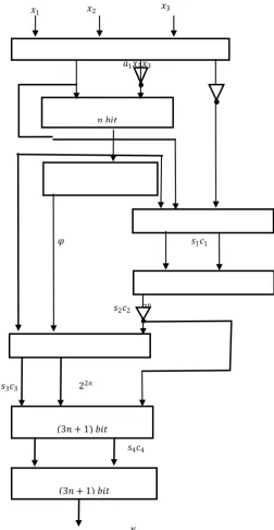
VI. Proposed Architecture
The residue number is converted to the Mixed Radix System (MRS) in parallel with the computation of the MRS, which detects and corrects primarily based on the non-redundant part. In the event of an error in any of the channels, the redundant part will be employed in the detection and correction of the residue digit error.The Mixed Radix Digits (MRDs) are computed according to equation (24) where all the MRDs 𝑎1, 𝑎2and 𝑎3 are computed
individually in equations (21) to (23). The 𝑎𝑖𝑠 which are the
MRDs for the non-redundant part are computed separately which is seen in Figure 1. As shown in Figure 1, 𝑎3 is computed using
Carry Save Adders (CSAs) 1, 2 and 3 and two regular (𝑛 + 1) bit Carry Propagate Adders (CPAs) 1 and 2 respectively. All the CSAs require an area of (𝑛 + 1)∆𝐹𝐴 each whilst CPAs 1, 2 and 3 require
an area of 𝑛 each. In order to obtain the MRD 𝑎3 will require a
total area of (11𝑛 + 4)∆𝐹𝐴. Regarding the delay, CSA (i.e. CSAs
1, 2 and 3) impose a delay of 𝐷𝐹𝐴 each in the reverse convertor.
CPAs 1 in the reverse convertor require a delay of (4𝑛 + 2)𝐷𝐹𝐴.
CPAs 2 and 3 in the reverse convertor require a delay of 6𝑛 +
2𝐷𝐹𝐴 each. The reverse convertor for the MRC also has one CSA that also impose a delay on the system. The total delay needed for the proposed scheme is (10𝑛 + 7)𝐷𝐹𝐴. The schematic diagram for
the proposed scheme is shown in Figure 1.
The schematic diagrams for the proposed scheme are shown below.
𝑎1𝑥2𝑥3
𝜑 𝑠1𝑐1
𝑠2𝑐2 2𝑛
𝑠3𝑐3 22𝑛
𝑠4𝑐4
[image:3.595.315.568.83.570.2]𝑋
Figure 1: Block Diagram of RC for the non-redundant part
VII. Numerical Results
Let us now consider some numerical illustrations with the proposed scheme.
Consider an (𝑛, 𝑘) code where n is the length of the code and k is the dimension of the code with the moduli set
𝑚1,𝑚2 , 𝑚3, 𝑚4, 𝑚5= (3,4,5,13,17) where 𝑚1, 𝑚2 and 𝑚3 are
non-redundant moduli, 𝑚4, 𝑎𝑛𝑑 𝑚5 are the redundant moduli. We
consider the integer message X=57, for its residue digits are 𝑥𝑖=
(0, 1, 2, 5, 6). The legitimate range = 𝑀𝑅= 3*4*5=60 and the
illegitimate range = 𝑀𝐾= 13*17 =221. Assume that during storage
or computation, an error occurs in the second residue digit such that 𝑟2=3. Therefore, the received codevector will be 𝑥 𝑖= (0, 3 , 2,
5, 6).
66873= 6687 4420 = 2267
66874= 6687 3315 = 57*
66875= 6687 2652 = 1383
𝑥1 𝑥2 𝑥3
Operand Preparation Unit(OPU)
𝑛 𝑏𝑖𝑡
CPA 1
Concatenate
CSA 1 (𝑛 + 1 𝑏𝑖𝑡)
CPA 2 (𝑛 + 1 𝑏𝑖𝑡)
CSA 2 𝑛 + 1 𝑏𝑖𝑡
(3𝑛 + 1) 𝑏𝑖𝑡
CSA 3
(3𝑛 + 1) 𝑏𝑖𝑡
668713= 6687 1020 = 567
668717= 6687 780 = 447
From the above calculation, it can be observed that there is only one legitimate projection with respect to the second moduli
𝑚2= 4 which falls within the legitimate range and it is the word
most likely sent. It can be seen and concluded from the above projections that the second residue (𝑟2) is in error and hence,
anytime it is involved in computation an erroneous output will be executed.
Using the same illustration given above, we now consider detecting and correcting the error using the moduli set.
The result for the iterative processes are shown below;
𝑟1, 𝑟2, 𝑟3, 𝑟4 =𝑋1234 = 447
𝑟1, 𝑟2, 𝑟3, 𝑟5 = 𝑋1235 = 747
𝑟1, 𝑟2, 𝑟4, 𝑟5 = 𝑋1245 = 1383
𝑟1, 𝑟3, 𝑟4, 𝑟5 = 𝑋1345 = 57*
𝑟2, 𝑟3, 𝑟4, 𝑟5 = 𝑋1345= 2272
From these results, it could be observed that whenever 𝑟2 is
involved in the computation it gives an illegitimate value i.e.
𝑋1234, 𝑋1235,𝑋1245 and 𝑋1345. When 𝑟2 was discarded in the 𝑋1345,
the recovered data is 57 which clearly indicates that 𝑟2 is the
erroneous digit. The conclusion is that the correct result is 57 and the error, which occurred in, 𝑟2 can be corrected by computing
𝑟2= 57𝑚𝑜𝑑4 = 1.
VIII. PERFORMANCE EVALUATION
The ability to detect and correct errors in a digital system improves its reliability and integrity. In this work, the MRC decoding technique is compared with the MP. It is found that the MRC decoding processes result in more computational steps in detecting and correcting errors in RRNS by dropping a residue at a time. The MP on the other hand detects and corrects single bit errors without going through more iterative steps in its implementation. A theoretical analysis shows that the MP recovers integer messages faster and improves computational speed than the MRC decoding processes as shown in Figure 2.
To evaluate the performance of the proposed scheme, the work is compared with Yangyang et. al [6]. Theoretically, the proposed scheme has less delay and computational complexity without compromising on accuracy as shown in Figures 3 and 4. Also, the proposed design employs simple adders (CSAs and CPAs) for its implementation. In the scheme of Yangyang et. al [6], twenty (20) latches which has an area of 9𝑛 and nine (9) ROMs with an area of
4𝑛2 were employed and that resulted into a total area requirement
[image:4.595.314.534.196.305.2]of (40𝑛2+ 20𝑛)∆ 𝐹𝐴.
Table 1: Area, Delay Comparison
Scheme Area(∆𝐹𝐴) Delay(𝐷𝐹𝐴)
Yangyang et. al [6] 40𝑛2+ 20𝑛 72𝑛2+ 40𝑛
Proposed 11𝑛 + 4 10𝑛 + 7
Figures 3 and 4 show the graphical illustrations of the area and delay comparisons.
Figure 2: Graph of Comparison between Modulus Projection and MRC Iterative Steps
Figure 3: Graph of area comparison of proposed scheme with Yangyang et. al [6] scheme
Figure 4: Graph of delay comparison of proposed scheme with Yangyang et. al [6] scheme
IX. CONCLUSION
The need to have efficient and faster algorithm in detecting and correcting errors cannot be ignored in digital systems. The algorithm presented is premised on both the Modulus Projection and the Mixed Radix Conversion. The MP considerably reduced the iterative steps and improved the speed of the architecture. Generally, the proposed scheme was built using simple adders instead of ROMs and latches that are associated with high cost of implementation. An area/delay analyses showed that there is a considerable improvement in the speed by 97% and tends to require about 96% less hardware resources in the proposed technique.
X. REFERENCES
[1] H. L. Garner, (1959), “The residue number system,” IRE Trans. Electronic Computers, Vol. 8, pp. 140-147. [2] F. Barsi & P. Maestrini, (1973), “Error Correcting
Properties of Redundant Residue Number Systems. IEEE Transactions of Computers, Vol. 22, No. 3, pp. 307–315. [3] A.F Behrouz, (2008). Data Communications and
Networking. Fourth Edition. Error Detection and Correction Computer, Vol. 23, No. 7, pp. 267-306. [4] D. M. Mandelbaum, (1972), “Error correction in residue
arithmetic,” IEEE Trans. Comput., Vol. 21, No. 6, pp. 538-545.
2267
57
1383
567 447
447 747
1383 57
2272
0 5000
1 2 3 4 5
Iterative Steps for the MRC and the MP
The MP The MRC
Numbe
r of
Int
ege
r
V
alue
0 5000
1 2 3 4 5 6 7 8 9 10
Comparison of Area
(Yangyang et al, 2008) Proposed
𝑛
0 10000
1 2 3 4 5 6 7 8 9 10
Comparison of Delay
(Yangyang et al, 2008) Proposed
De
lay
𝑛
[image:4.595.315.534.341.452.2] [image:4.595.36.287.583.663.2][5] Szabo, N. & Tanaka, R. (1967). Residue Arithmetic and its Application to Computer Technology. MC-Graw-Hill, New York.
[6] Yangyang T., Boutillon E., Jégo C., & Jézéquel M. (2008). A new single-error correction scheme based on Self-Diagnosis Residue Number Arithmetic. Conference on Design and Architectures for Signal and Image
Processing (DASIP) pp. 27–33. doi:
10.1109/DASIP.2010.5706242
[7] W. K. Jenkins, C. Radhakrishnan, & S. Pal (2007), Fault Tolerant Signal Processing for Masking Transient Errors in VLSI Signal Processors,” Proceedings IEEE International Symposium on Circuits and System (ISCAS), pp. 2570 – 2573
[8] O. Goldreich, D. Ron & M. Sudan (2000). Chinese Remaindering with Errors”, IEEE Trans. Infor. Theory, Vol. 46, pp.1330-1338.
[9] M.I. Daabo, & K.A. Gbolagade (2014). An Overflow Detection Scheme with a Reverse Converter for the Moduli set {2𝑛− 1, 2𝑛, 2𝑛+ 1}. Journal of Emerging
Trends in Computing and Information Sciences, ISSN 2079-8407, Vol. 5, No. 12, pp. 931-935.
[10] A.S. Molahosseini, & K. Navi (2007). New Arithmetic residue to binary Converters.
![Figure 3: Graph of area comparison of proposed scheme with Yangyang et. al [6] scheme](https://thumb-us.123doks.com/thumbv2/123dok_us/677285.1075021/4.595.315.534.341.452/figure-graph-area-comparison-proposed-scheme-yangyang-scheme.webp)
