University of Windsor University of Windsor
Scholarship at UWindsor
Scholarship at UWindsor
Electronic Theses and Dissertations Theses, Dissertations, and Major Papers
2014
Determination of Optimal Power for ZigBee-based Wireless
Determination of Optimal Power for ZigBee-based Wireless
Sensor Networks
Sensor Networks
Okhamila Yusuf
University of Windsor
Follow this and additional works at: https://scholar.uwindsor.ca/etd
Recommended Citation Recommended Citation
Yusuf, Okhamila, "Determination of Optimal Power for ZigBee-based Wireless Sensor Networks" (2014). Electronic Theses and Dissertations. 5135.
https://scholar.uwindsor.ca/etd/5135
This online database contains the full-text of PhD dissertations and Masters’ theses of University of Windsor students from 1954 forward. These documents are made available for personal study and research purposes only, in accordance with the Canadian Copyright Act and the Creative Commons license—CC BY-NC-ND (Attribution, Non-Commercial, No Derivative Works). Under this license, works must always be attributed to the copyright holder (original author), cannot be used for any commercial purposes, and may not be altered. Any other use would require the permission of the copyright holder. Students may inquire about withdrawing their dissertation and/or thesis from this database. For additional inquiries, please contact the repository administrator via email
i
Determination of Optimal Power for ZigBee-Based
Wireless Sensor Networks
By
OKHAMILA ALI YUSUF
A Thesis
Submitted to the Faculty of Graduate Studies
through the Department of Electrical and Computer Engineering
in Partial Fulfillment of the Requirements for the Degree of Master of Applied Science
at the University of Windsor
Windsor, Ontario, Canada
2014
ii
Determination of Optimal Power for ZigBee-Based
Wireless Sensor Networks
by
Okhamila Ali Yusuf
APPROVED BY:
______________________________________________
A. Asfour Department of Civil & Environmental Engineering
______________________________________________ M. Khalid
Department of Electrical & Computer Engineering
______________________________________________ J.Wu, Co-Advisor
Department of Electrical & Computer Engineering
______________________________________________ K.Tepe, Advisor
Department of Electrical & Computer Engineering
iii
DECLARATION OF ORIGINALITY
I hereby certify that I am the sole author of this thesis and that no part of this
thesis has been published or submitted for publication.
I certify that, to the best of my knowledge, my thesis does not infringe upon
anyone’s copyright nor violate any proprietary rights and that any ideas, techniques,
quotations, or any other material from the work of other people included in my thesis,
published or otherwise, are fully acknowledged in accordance with the standard
referencing practices. Furthermore, to the extent that I have included copyrighted
material that surpasses the bounds of fair dealing within the meaning of the Canada
Copyright Act, I certify that I have obtained a written permission from the copyright
owner(s) to include such material(s) in my thesis and have included copies of such
copyright clearances to my appendix.
I declare that this is a true copy of my thesis, including any final revisions, as
approved by my thesis committee and the Graduate Studies office, and that this thesis has
iv ABSTRACT
In designing WSNs, both the transmit power, network topology, and routing
scheme are considered. Transmitting at lower power affect the connectivity of the
network while transmitting at excessive power reduces the lifetime of nodes and
increases the network interference. Thus, determining the optimal power of the nodes that
will be necessary to guarantee network connectivity. In this work, a practical self-healing
and self-configuring real life prototype ZigBee Wireless Mesh Sensor Networks
(WMSNs) was design to evaluate the performance of IEEE 802.15.4/ZigBee. We showed
that increasing the transmit power of nodes from -6dBm to 0dBm in WMSNs leads to
improved packets delivery ratio and throughput improvement and the optimal power was
-2dBm for the studied topology. The testbed will aid wireless sensor network designer to
make an accurate decision on transmit power and mesh network topology using Ad-hoc
v DEDICATION
vi
ACKNOWLEDGEMENTS
All praises and adoration are due to the Almighty God for his inspiration,
guidance and blessings throughout my academic pursuit at the University of Windsor.
My immense gratitude to my Advisor Dr. K. Tepe, whose encouragement and assistance
helped achieved the completion of this research work and my Co-Advisor, Dr. J. Wu for
his assistant and advice throughout my studies.
I also wish to appreciate the invaluable support and assistance given to me by
Mrs. Andria Ballo, throughout my studies. My special appreciations to my mother, Mrs.
F. I Ali, for her love and care. May Almighty God grant you good health and long life
(Ameen). I also appreciate the effort of all my siblings throughout the course of my
program for their prayers; May Almighty Allah continues to assist you all (Ameen).
Finally, I would like to show my appreciation and regards to all the people in my
laboratory who contributed in one way or the other to the successful completion of this
vii
TABLE OF CONTENTS
DECLARATION OF ORIGINALITY ... iii
ABSTRACT ... iv
DEDICATION ...v
ACKNOWLEDGEMENTS ... vi
LIST OF TABLES ... xi
LIST OF FIGURES ... xii
LIST OF ABBREVIATIONS/SYMBOLS ... xiii
CHAPTER ONE - INTRODUCTION...1
1.1 Background ...1
1.2 Motivation ...3
1.3 Problem Statement ...3
1.4 Thesis Contribution ...4
1.5 Node Architecture ...4
1.5.1 The Sensing Subsystem ...5
1.5.2 The Communication Subsystem ...6
1.6 Objective ...6
1.7 Thesis Organization...7
CHAPTER TWO - LITERATURE REVIEW ...8
viii
2.2 ZigBee Stack ...9
2.2.1 Application Layer ...10
2.2.2 Network Layer ...10
2.3 Types of ZigBee Devices ...11
2.3.1 ZigBee Coordinator (ZC) ...11
2.3.2 ZigBee Router (ZR) ...11
2.3.3 ZigBee End Device ...12
2.4 ZigBee Network Topology...13
2.4.1 Cluster Tree Topology ...13
2.4.2 Mesh Topology ...14
2.5 ZigBee Addressing ...15
2.6 ZigBee Data Transmission ...15
2.6.1 Unicast Transmission ...16
2.6.2 Broadcast Transmission ...16
2.7 RF Packet Routing ...17
2.7.1 AODV Mesh Routing ...17
2.7.2 Many-to-One Routing ...19
2.7.3 Source Routing...19
2.8 Applications of ZigBee ...20
ix
3.1. Introduction ...21
3.2 Digi XBee Pro S2B RF Module ...21
3.3 Arduino Uno Board ...23
3.4 XBee Shield...23
3.5 XBee Explorer Dongle ...24
3.6 RF Module Operation...24
3.7 Firmware Description ...25
3.7.1 Forming a ZigBee Network ...26
3.8 XBee Pro S2B RF Operation Mode ...27
3.8.1 Transparent Operation (AT) ...27
3.8.2 Application programming Interface Operation (API)...27
3.9 Modes of Operation ...28
3.9.1 Transmit Mode ...28
3.9.2 Receive Mode ...29
3.9.3 Command Mode...29
3.9.4 Sleep Mode ...29
3.10 Programming XBee Pro S2B Modules ...30
3.10.1 Modules Configuration Using the API Operation ...30
3.10.2 API Frame Specifications ...30
x
3.10.4 API Frame Structure ...31
CHAPTER FOUR – TESTBED AND RESULTS ...41
4.1 Introduction ...41
4.2 Testbed and X-CTU Interface ...43
4.3 Network Deployment and Settings ...44
4.4 Performance Metrics ...46
4.4.1 Packet Delivery Ratio ...46
4.4.2 Network Throughput ...47
4.5 Experimental Procedure and Result Analysis ...47
4.5.1 Packets Delivery Ratio Vs Transmitted Power ...48
4.5.2 Throughput Measurement At Different Transmit Power...49
4.5.3 Graph of Throughput (Kbps) At Different Baud Rate ...51
CHAPTER FIVE – CONCLUSIONS AND FUTURE WORK ...52
5.1 Conclusions ...52
5.2 Future Work ...53
REFERENCES ...54
xi LIST OF TABLES
Table 1 - XBee Module Pin Description... 22
Table 2 - API Frame Names and Values. ... 33
Table 3 - API format for ZigBee TX request. ... 34
Table 4 - Explicit Addressing ZigBee Command Frame. ... 36
Table 5 - Transmit Status Frame. ... 38
xii LIST OF FIGURES
Figure 1 - A Typical Wireless Sensor Networks Architecture. ... 2
Figure 2 - Architecture Of Wireless Sensor Node. ... 5
Figure 3 - ZigBee Stack Architecture. ... 9
Figure 4 - ZigBee Node Types. ... 12
Figure 5 - ZigBee Network Topologies. ... 14
Figure 6 - Broadcast Data Transmission. ... 16
Figure 7 - Transmission Through A Mesh Network. ... 18
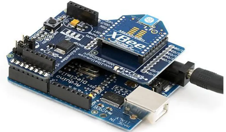
Figure 8 - XBee module attached to shield and Arduino Board. ... 24
Figure 9 - UART Data Frame Structure. ... 30
Figure 10 - UART Data Frame Structure -Escape Control Character ... 31
Figure 11 - UART Data Frame & API Specific Structure. ... 31
Figure 12 - X-CTU Modem Configuration Snapshot-1. ... 41
Figure 13 - X-CTU Modem Configuration Snapshot-2. ... 42
Figure 14 - Testbed and X-CTU Interface. ... 43
Figure 15 - Network Deployment and Setting. ... 45
Figure 16 - Graph of PDR at different values of transmit power. ... 48
Figure 17 - Graph of Throughput (kbps) vs Number of Hops. ... 50
xiii
LIST OF ABBREVIATIONS/SYMBOLS
AMR Advance Meter Reading
ADC Analog to Digital Converter
AODV Ad-hoc On-Demand Distance Vector
API Application Programming Interface
APS Application Support Sub-layer
FTDI Future Technology Devices International
GUI Graphical User Interface
HVAC Heating Ventilation and Air Conditioning
IEEE Institute of Electrical and Electronics Engineers
ISM Industrial Scientific and Medical
MAC Media Access Control
MEMS Microelectromechanical Systems
PAN Personal Area Network
PHY Physical Layer
ROM Read Only Memory
SCADA Supervisory Control and Data Acquisition
UART Universal Asynchronous Receiver/Transmitter
USB Universal Serial Bus
VLSI Very High Scale Integration
WSN Wireless Sensor Networks
ZC ZigBee Coordinator
1
CHAPTER ONE - INTRODUCTION
1.1 Background
A Wireless Sensor Network (WSN) is an ad-hoc network involving a spatially
distributed autonomous system that are capable with the help of sensors to monitor
physical or environmental situations, such as current, temperature, pressure, and they
cooperatively transmit the data to the main location of the application. These types of
sensors have both data processing and communication capabilities and are deployed both
in outdoors and indoors applications like; security and battlefield surveillance, industrial
monitoring and controls, machine health monitoring, traffic control and personal health
monitoring.
The WSN is made up of many tiny low power devices from several hundred to
thousands called "nodes" where each of the nodes is associated to one or several sensors
in the network by communicating with each other directly or through other nodes [1].
Each of the sensor nodes consists of a radio transceiver with an antenna, a
microcontroller, which is a circuit for interfacing with the sensors and a battery source.
Different resource constraints lead to the cost of a node and size, result in corresponding
energy constraints, communication's bandwidth, memory and computational speed of
sensor nodes. WSN topology can be a star network or multi-hop wireless mesh topology.
The hops network can also have different propagation technique as flooding or routing [1,
2]. Figure 1 shows typical Wireless Sensors Networks (WSN) with nodes transmitting
2
Figure 1: A Typical Wireless Sensor Networks Architecture [1]
A typical WSN have the following characteristics:
They have large number of nodes
A typical WSN node has the ability to withstand harsh operating conditions
It has the ability to contain node failures
Ease of deployment
In typical WSN, there is power consumption constraints for nodes using energy
harvesting or batteries
Node heterogeneity
They are data centric; which means that the communication be targeted to the
3
1.2 Motivation
Sensors capture and reveal real-world phenomena and transform these into a form
which can be stored and processed. Sensors provide several societal benefits as they are
integrated into devices, machines, and environments [1]. They can enhance security and
surveillance, improve productivity, prevention of catastrophic infrastructural decay or
failures and enable new applications such as Automatic Meter Reading (AMR), smart
agriculture and smart home applications. Advances in technologies like
Microelectromechanical Systems (MEMS), Very Large Scale Integrations (VLSI), and
wireless technology contributed immensely to the wide acceptance of distributed sensor
systems [3, 4]. For example, the miniaturization of sensing and computing technologies
leads to the development of low-power, and inexpensive sensors, actuators, and
controllers [3]. There is a great attention on systems that can monitor and protect bridges
and tunnels, pipeline infrastructure and power grid. Large networks of sensor nodes are
currently being deployed to monitor vast geographical areas for forecasting environment
pollution and flooding, to monitor pesticides to improve crop's health, monitoring water
usage, fertilizers, and structural health of bridges with the help of vibration sensors [4, 5].
1.3 Problem Statement
One of the most problematic issues in wireless sensor networks is conservation of
power, where nodes depend on limited battery power. Transmitting at low power can
affect the connectivity of the network while transmitting at excessive power not only
4
the network's lifetime. Thus, determining the optimal power of the nodes that will be
necessary to guarantee network connectivity is necessary.
1.4 Thesis Contribution
To properly design a robust mesh network system, is important to know the
communication components of the system. Hence, real life prototype ZigBee wireless
mesh sensor network is designed to evaluate the performance of IEEE 802.15.4/ZigBee.
The testbed will aid wireless network designer to make a proper decision on each of the
transmit power, network topology and the routing scheme.
1.5 Node Architecture
The sensor nodes (wireless) are the central devices in a WSN. A node can sense,
process and communicate. It also stores, executes the communication protocols and the
algorithm for data-processing. The physical resources of the node influenced the size,
quality, and sensed data frequency which can be extracted from the network [3]. Figure 2
display the diagram of a sensor node, which consists of sensing parts, processing,
5
Figure 2: Architecture of Wireless Sensor Node [1]
1.5.1 The Sensing Subsystem
This subsystem combines physical sensors to produce ADC converters and the
multiplexing mechanism to distribute them [1]. The sensors usually interface both the
virtual and the physical world. Sensing of the physical phenomena is not unfamiliar, but
the advent of MEMS made sensing a ubiquitous process. Physical sensor includes a
transducer, which converts from one form of energy into another, usually into an
electrical (voltage) [1, 2]. The transducer output is an analog signal, so ADC is needed to
6
1.5.2 The Communication Subsystem
The communication subsystem is an important energy intensive subsystem as such,
power consumption must be minimized. In most cases, all the commercially available
transceivers have a controlling functionality to regulate the transceiver between active
and inactive states (idle and sleep) [1]. With the help of this system, the sensor node
communicates with the base station and other nodes. To replace or change sensor nodes
that are battery powered is difficult, especially in cases where huge numbers of nodes are
deployed. Hence, every aspect of the network regarding sensing devices, communication
algorithms, and localization algorithms must be energy efficient [7].
The processor subsystem brings all other subsystems together. Its main aim is to
process instructions regarding sensing, communication and self-organization. It consists
of a processor chip, an internal flash memory to store program directions, memory that
temporarily stores the sensed data, and internal clock, among other things [1].
Wireless sensor node subsystems are communicated via peripheral interface (SPI),
inter-integrated circuit (12C) and universal serial bus (USB).
1.6 Objective
Evaluate the impact of transmit power on ZigBee WMSNs within a real testbed
and show that optimal transmit power leads to better network.
Determine how trasmit power affect wireless mesh networks topology using
ZigBee.
7
To implement a real life prototype ZigBee wireless mesh sensor network based on
AODV at different power level.
1.7 Thesis Organization
The rest of this thesis is organized as follows: In Chapter 2, we look into related work and
general overview of ZigBee technology. Chapter 3 will give detailed descriptions of both
the hardware and software used to achieve these results. Chapter 4 will discuss the
test-bed, methodology, results and discussion of results. While Chapter 5, will present the
8
CHAPTER TWO - LITERATURE REVIEW
2.1 Introduction
ZigBee is the IEEE 802.15.4 MAC and PHY layers designed for low bandwidth,
low-power, low-cost, wireless mesh network standard [8]. The mesh networking
capability provides high reliability and longer ranges applications while the low cost
enables the technology to be used in monitoring and controls of wireless applications, and
a low power consumption guarantee a longer life for the batteries [9]. ZigBee operates in
the Industrial, Scientific and Medical (ISM) radio bands which include; 868MHZ in
Europe, 915MHZ in both Australia and United States of America and 2.4GHZ frequency
band worldwide. Data transmission ranges from 20kb/s to 250kb/s in the 868MHZ to
2.4GHZ frequency band [8, 9].
ZigBee network layer supports peer-to-peer, cluster trees and generics mesh
network topologies. The IEEE 802.15.4 standard, defines both the "Medium Access
Control layer (MAC)" and "the physical layer" while ZigBee is built upon these two
layers. Thus, both standards complete the communication protocol stack which defined
WSN.
The ZigBee Alliance is a growing consortium of over 300 companies including
semiconductors, module, stack, and software developers [11] that came together to form,
maintain and published the ZigBee standards [10]. ZigBee is a trademark registered by
this group that helps multiple vendors to produce interoperable products. IEEE 802.11
9
general public has free access to the ZigBee specification for non-commercial purpose
[10].
2.2 ZigBee Stack
The ZigBee stack architecture includes the MAC, PHY, Network and the
Application support sub-layer (APS) blocks called "layers". Technically each of the
layers assists the layer above it. Figure 3 shows the typical ZigBee protocol stack
architecture which define the different layers
10
2.2.1 Application Layer
The ZigBee application layer is the top-level layer which consists of sub-layers
viz; the application support sub-layer (APS), the Application framework (AF), the
ZigBee Device Objects (ZDO) and the manufacturer defined application objects [14].
The application layer is the interface between ZigBee and users and the system
[10]. The ZigBee Device Object (ZDO) is responsible for device management and
advanced network management, and it also helps to define the role of the coordinator,
router or end device. It initiates and responds to binding requests and provides address
management of the device, security, discovering new devices on the network and their
services.
The application support sub-layer (APS) helps to maintain the binding tables
which define devices and services they can offer. The APS work as a bridge between
network layers, and other components of the application layer [10].
2.2.2 Network Layer
This layer provides routing functions to the network to enable data packets route
between devices (milt-hops) from the source to destination. Both the discovering and
storage of neighbor information on routing tables is done at this layer, and also
maintaining the routes between these devices. The network layer of a ZigBee coordinator
is responsible for assigning 16-bit network address to new devices joining the network
11
2.3 Types of ZigBee Devices
ZigBee has three types of devices that can participate in building a wireless sensor
network. There are; coordinator, router and end devices
2.3.1 ZigBee Coordinator (ZC)
This is the most capable device type and needs maximum memory as well as high
computing power. Every ZigBee network has only one coordinator.
ZC has the following characteristics
It stores and maintain network information
It act as both the repository for security keys and trust center [12]
Selects a personal area network identifier (PAN ID) and a channel to run the
network.
Permits both the routers and end devices access to join the network [11]
Assist in routing packets and can also be a source or destination for data packets
[11]
Does not sleep and help sleeping end device to buffer RF data packets.
2.3.2 ZigBee Router (ZR)
ZigBee router acts as a link between routers by transferring data from other
devices. However, it must have the same PAN ID with the network before it can receive,
transmit or route data [11]. It also stores and maintains network information and uses the
12
it allows other end devices and more routers to join the network, when the memory and
computing power improved, it can also function as a coordinator of the network.
2.3.3 ZigBee End Device
ZED has limited functions as compared to router and coordinator, it cannot route
data, and it transmit and receive RF data with the help of the coordinator and router. This
characteristic is done to allow the node to be asleep to prolong the battery life [9].
This node requires fewer amounts of memory and energy to reduce cost and complexity.
Figure 4: ZigBee Node Types [11]
Figure 4 shows a ZigBee network, displaying the coordinator(C), routers(R) and
end devices (E). The coordinator starts the network by selecting a PAN ID (64-bit and
16-bit) and channel. The end device joins the network through the coordinator or router
and any of these devices that permit it to join automatically becomes the “parent” of the
13
parent and the parent must help its device to buffer or retain incoming data packets when
it is asleep [9, 11, 15].
2.4 ZigBee Network Topology
ZigBee network supports star, cluster tree and mesh topologies [9, 11]. The
network in a star topology is controlled by the coordinator which is responsible for
starting and maintaining all the devices in the network. All the end devices communicate
with the coordinator directly. Hence, any exchange of packets between the end devices
must always pass through the coordinator which may leads to congestion at the
coordinator as there is no alternative route from source to destination.
2.4.1 Cluster Tree Topology
This type of network consists of a coordinator, End devices and several routers.
The router function is to extend the coverage of the general network. Routers use the
hierarchical routing strategy for data routing and to control messages across the network
[16]. In this type of network if either the coordinator or router is disabled, the end device
of the disable device is not able to communicate with other devices in the network. A
special case of tree topology is called a cluster tree topology where parent with its
children is called a cluster [17]. Figure 5 shows the structures of the different network
14
Figure 5: ZigBee Network Topologies [13]
2.4.2 Mesh Topology
This type of network consists of a coordinator, routers and end devices [18]. The
topology has multi-hop capability as it allows data packets route through several devices
called multi-hops to reach its intended destination. Multipath routing leads to high
reliability. This type of protocol is more robust and its uses a more complex routing
protocols compared to star or tree topology. Mesh topology is a form of ad-hoc network,
is self-healing and self-organizing. It also has high fault tolerance which is due to its
15
2.5 ZigBee Addressing
ZigBee devices have a bit and 16-bit address [11]. Each ZigBee node has a
64-bit unique address which is allocated during manufacturing and it is a permanent address
which uniquely identifies a node. Each ZigBee node is assigned a 16-bit address called
the network address when the node joins a network. This address is unique to all the
physical devices in a particular network. However, this type of address is not a permanent
address like the 64-bit address. Apart from the coordinator, which has a 16-bit address of
0x0000 all other devices is assigned a randomly generated address from the coordinator
or router node that allows the join [11, 15]. The 16-bit address can be changed, when it is
discovered that two devices in the same network have the same 16-bit address and when
a node leaves the network and rejoins the same network [9, 15]. ZigBee transmissions are
sent using both the source and destination 16-bit network addresses [11]. Since the 16-bit
address is not permanent, it is a non-reliable method to identify a device but the routing
tables on each node use the 16-bit address to determine how to route data across the
network. A 64-bit address must be included in the transmissions of data to guarantee that
data is delivered to the appropriate device [11, 9].
2.6 ZigBee Data Transmission
All ZigBee data packets are transmitted using the device and application layer
addressing field [20]. Data packets can be transmitted as either broadcast or unicast
16
2.6.1 Unicast Transmission
A unicast transmission routes data from source to destination device [8], where
the destination of the message can be nearest- neighbor or multi-hops away.
2.6.2 Broadcast Transmission
A broadcast message with a ZigBee network is a message sent to all the devices
in the network. To ensure the message gets to all the devices, the routers and the
coordinator must broadcast the message three times to other devices when they received
the message. This type of transmission is shown in figure 6.
17
When a node transmits a broadcast, it will create an entry in a broadcast
transmission table, which is used to keep track of each broadcast that is received to make
sure the packets are not endlessly transmitted [11]. The broadcast transmission table can
holds eight entries and each of the entry continue for only eight seconds. The broadcast
messages should be sparingly used since transmissions of broadcast are retransmitted by
each node in the network [20]. When a node transmits a broadcast transmission, it
confirms to ensure all neighbors also transmit the data message. If any of the neighbor
nodes do not also transmit the data packets, the node then re-send the broadcast message
and wait for its neighbor nodes to retransmit the broadcast message [15].
2.7 RF Packet Routing
ZigBee have three different ways of routing data, each of this technique has its
own advantages and disadvantages, which are; Ad-hoc On-demand Distance Vector
(AODV) mesh routing, many-to-one routing and source routing.
2.7.1 AODV Mesh Routing
ZigBee mesh network employs routing techniques to establish a link between a
source node and the destination. In this type of network, data packets pass through
several hops (multi-hops) to their intended destinations. The coordinators and end devices
uses a process called route discovery to find a link between source and destination. This
18
Figure 7: Transmission through a Mesh Network [11]
In AODV routing protocol, routing across the mesh is table driven, in this case
each node store the next hop for a link to the destination node. Usually, the network is
silent until a path is required to a particular destination. If a next hop is not known, route
discovery is used to determine the path to the node [11]. In this process, a node
requesting a connection, broadcasts a route request for connection and other nodes on the
same network forward the message and store the sender information there by establishing
a route back to the sender. When any of the nodes receive the message and have a route
to the needy node, it sends back a route reply to the node requesting the route and this
node select the more efficient route to the destination. In a more complex application
where a device need to send a message to several remotes devices, AODV routing will
need to perform a route discovery for each destination node to established a route. If there
are less routing table entries with more destination devices, the AODV routes already
19
This can leads to high delay of data packets and poor performance of the network. In this
type of condition, it is highly recommended to use many-to-one routing and source
protocols [11].
2.7.2 Many-to-One Routing
AODV mesh routing will need significant overhead where several devices will
have to transmit data to a central collector. The network will be flooded with messages if
each node had to discover a route before sending data to the collector [21].
Many-to-one routing will be an optimization for a network of this type [11]. A
single many-to-one broadcast transmission is sent from the data collectors in order to
establish a reply routes on all devices. In the routing, devices that receive the route
request message often establish a reverse many-to-one routing entry table to establish a
route to the collector [21].
2.7.3 Source Routing
Source routing is applied in a network where many-to-one routes have been
established from remote nodes to the data collector Centre. This routing algorithm
permits the collector to store and specify routes for several remotes unlike in
many-to-one routing that establishes routing paths from many devices to a single data collector
[11]. Generally, many-to-one routing is recommended in a network that have more than
20
2.8 Applications of ZigBee
ZigBee protocols are wireless technology designed for embedded applications
requiring low data rates and low power consumption [10]. To pass ZigBee certification,
each device must have a battery life of not less than two years.
Typical ZigBee application includes:
Building automation
Industrial control and monitoring
Medical application for patient and fitness monitoring
Embedded sensing
Wireless sensor networks
Automatic meter reading (AMR)
Traffic control, street lights control, and signal lights control and
Fire safety alarm and building monitoring
Heating ventilation and air conditioning (HVAC)
Security and surveillance
21
CHAPTER THREE -HARDWARE AND SOFTWARE DESCRIPTION
3.1. Introduction
For this experiment, XBee pro S2B, from Digi international, model
XBP24BZ7SIT were used. Each of the modules was equipped with a wire antenna with
Digi-key part number A24-HASM-450-ND, Arduino Uno board and an XBee shield
(Dev-08471) and an XBee explorer dongle.
3.2 Digi XBee Pro S2B RF Module
The XBee pro series 2B version is a robust RF module suitable for wireless sensor
networks and is loaded with ZigBee firmware. It is designed to support low power, low
cost wireless sensor networks. This module allows one to design a more complex and
robust mesh networks based on the XBee ZigBee mesh firmware. The module improves
reliability at minimal power and support communication between computers,
microcontrollers and similar devices. The modules operate within the Industrial,
Scientific and Medical (ISM) 2.4GHZ frequency band. Table 1 shows the XBee pro S2B
22
Table 1: XBee Module Pin Description [11]
Name Direction Default stat Description
1 VCC - - Power supply
2 DOUT Output Output UART Data Out
3 DIN/CONFIG Input Input UART Data In
4 DIO 12 Both Disable Digital I/O 12
5 RESET Both
Open-Collector with pull-up
Module Reset (reset pulse must be at least 200 ns)
6 RSSI PWM/DIO 10 Both Output RX Signal Strength Indicator/Digital IO
7 DIO 11 Both Input Digital I/O 11
8 [reserved] - Disable Do not connect
9 DTR/SLEEP_RQ/DIO8 Both Input Pin Sleep Control Line or Digital IO 8
10 GND - - Ground
11 DIO4 Both Disable Digital I/O4
12 CTS/DIO7 Both Output Clear-to-Send Flow Control or Digital
I/O7. CTS, if enabled, is an output
13 ON/SLEEP Output Output Module Status Indicator or Digital I/O 9
14 VREF Input - Not used for EM250. Used for
programmable secondary processor. For compatibility with clear XBEE modules, we recommend connecting this pin voltage reference if Analog sampling is desired.
Otherwise, connect to GND
15 Associate/DIO5 Both Output Associated Indicator, Digital I/O 5
16 RST/DIO6 Both Input Request-to-send Flow Control, Digital
I/O 6. RTS, if enabled, is an input
17 AD3/DIO3 Both Disable Analog input 3 or Digital I/O 3
18 AD2/DIO2 Both Disable Analog input 2 or Digital I/O 2
19 AD1/DIO1 Both Disable Analog input 1 or Digital I/O 1
20 Commissioning Button Both Disable Analog input 0 or Digital I/O 0, or
23
3.3 Arduino Uno Board
The Arduino Uno board is a portable microcontroller platform based on Atmega
328 with complementary parts to facilitate programming and incorporate into other
circuits with the aid of a universal serial bus (USB) port to connect any applicable device
to the computer. The open source nature and ease of use makes it a high demand device.
The board does not use the FTDI USB-to-serial driver chip, but it uses the
Atmega16U2 program as a USB-to-Serial connector [7]. It has fourteen (14) digital
input/output pins, USB connection, power jack, 16MHZ ceramic resonator, ICSP header,
and a reset button. It can be connected with the computer by connecting to a power
source or using a USB cable.
3.4 XBee Shield
The XBee shield is used with Arduino USB board to wirelessly communicate
with ZigBee Protocol using XBee module by Digi International. This module can be used
in a command mode or as a USB/Serial replacement. The shield jumpers are used to
determine how its serial communication can connect to that between how its serial
communication can connect to that between the microcontroller and FTDI USB-to-Serial
chip on the Arduino Uno board. When the jumpers are position in the USB position the
input pin (DIN) on the XBee pro module will be connected to the TX pin of the FTDI
chip and the output pin (DOUT) will be connected to the Rx pin of the FTDI chip [24].
Also, when the jumpers are in the XBee position, the DIN is connected to TX and DOUT
24
3.5 XBee Explorer Dongle
The XBee module can be attached to the explorer Dongle and plug directly into
the USB port without the need for a cable. It has an on-board voltage regulator up to
500mA
3.6 RF Module Operation
The XBee pro S2B RF module can communicate through its serial port with any
logic and voltage compatible UART device through a logic-level asynchronous serial
port [11]
25
Figure 8 comprises of an Arduino Uno board, an XBee shield attached, and XBee
module connected to a power source. This is acting as a sensor node. Asynchronous serial
signal enters the module through the DIN (pin3) and the signal should be idle when there
is no data transmission. Figure 8 shows the serial bit pattern of data passing through the
module [21].
Each of the data byte includes 8 data bits, start bit and stop bit. Both timing and
parity checking required for data communications are performed by the UART module.
Two UARTS are needed to be configured with compatible settings for serial
communications.
3.7 Firmware Description
Firmware is a software program or instructions programmed in the device’s
memory which controls the device and provides several instructions on how the devices
can communicates with the other computer hardware. Firmware is stored in flash ROM
that can be erased and rewritten. Examples of systems that contain firmware are
embedded systems, computers digital cameras, and mobile phones.
Digi International make available for free, the proprietary firmware for XBee
device with the provision of changing the behavior using a software called X-CTU with
graphical user interface by setting the parameters as desired and other variable of the
26
3.7.1 Forming a ZigBee Network
ZigBee Personal Area Network (PAN) is formed when the coordinator searches
for an available channel and select a PAN ID to start a network. Then after, the routers
and end devices can now join the network using the PAN ID (Personal Area Network
Identifier). The coordinator allocates a 16-bit network address to any router or end device
joining the network. The coordinator network address is usually 0x0000. The router has
ability to allow end devices join the network, when a particular node allows any node to
join a network, the node that allow it, is called the parent while the node joining is called
the child. Hence, joining a network, established parent and child relationships.
The new node need to first of all scans for channels that are free and identifies
which it will join. In some cases, multiple networks exist in the same channel; these
channels are distinguished by their PAN IDs. [21] A router or end device issue a beacon
request frame on the channel and listen to see multiple coordinators and routers with the
same PAN ID. A closer coordinator or router will reply to the beacon request by
transmitting a beacon which contains the device information, in which case it selects the
best one to connect to, usually one with best signal strength with valid PAN ID and send
an associate request frame. If it is accepted, the node finally joins the network. Routers
that join the network are able to route data packets unlike end devices that cannot allow
27
3.8 XBee Pro S2B RF Operation Mode
The XBee modules operate in two modes, which are; the application
programming Interface (API) and transparent mode operation.
3.8.1 Transparent Operation (AT)
In transparent mode (AT), the transmitting XBee radio relay serial data to the
receiving one as indicated by the Destination Address High (DH) and Destination
Address Low (DL) parameters [21]. This operation is a simple operation designed for
point to point communication between transmitting and receiving XBees. In other to
communicate with multiple XBees, a command mode needs to be activated each time to
change the destination address of the XBee. When UART data is received through the DI
pin is queued up for RF transmission but RF data received which is addressed to the
module’s 64-bit Address is sent out to the DO pin [15].
3.8.2 Application programming Interface Operation (API)
API operation is a more robust alternative to the transparent operation. In this
operation, packets are sent more quickly, predictably, and reliably using frames that have
a unique format of arrangement. This frame can be generated using the frame generators
in X-CTU. Thus, this frame improves the level a host application interacts with the
networking capabilities of the modules [23]. The send transmit data frames in API always
include; the command frame which is equivalent to the transparent mode operation (AT)
28
RF-received data frame, the command response and event notifications as associate,
disassociate or reset [11].
At the host application layer, API provides another way of configuring modules
and route data. In this process, instead of modifying addresses using the command mode
like in AT operation, the host application transmit data frames to the module that contain
the address and payload information. The module will transmit data frames to the
application which contains status packets, source and payload information from received
data packets [15]. API operation option help to facilitates transmitting packets data to
multiple destinations without the use of command mode like in AT operation, also,
receive acknowledgement (ACK) for each packet transmitted which indicate the packet
was successfully delivered. The transmitting XBee resend any packet if an
acknowledgement is not received. All receive packets (RX) contain the source address of
transmitting radio which identify the source address of each received packet and usually,
packets always include checksum for data integrity [11].
3.9 Modes of Operation
The RF module can operate in the Transmit Mode, Receive Mode, Sheep Mode
and Command Mode. The module always remains in idle mode when not transmitting or
receiving any data during this state, RF module constantly check for valid RF data.
3.9.1 Transmit Mode
RF module change from idle mode to transmit mode, immediately it receives
29
path to the destination and the 16-bit network address are known [11]. In the case where
both the destination and network address is not known, route discovery takes place to
determine both. If route discovery is not successful in the discovery both in the
destination and network address, the packet is immediately discarded until a route is
estimated. When message is sent from a source node to the destination node,
acknowledgement is send to the source node to confirm that the packet was received.
When an acknowledgement is not received, the source node will re-send the data packet.
3.9.2 Receive Mode
When an RF packet is received at the source, and the packet is valid then the data
is transferred to serial transmit buffer.
3.9.3 Command Mode
Command mode is a state when receiving serial characters are interpreted as
commands and to be able to read RF module parameters or modify RF data; it must go
into command mode [11].
3.9.4 Sleep Mode
Since routers and coordinators are involved in data routing they consume more
power than the end device, as such the routers and coordinators are mains powered. In
sleep mode, RF module remains in a state of low power consumption when not in use.
Only end devices are supported by the sleep mode. The end device parent must be able to
buffer incoming data packets sent to the end device when asleep until is awake to receive
30
command to its parent coordinator or router to inform it that is available. When the
command is received, it will forward any data packets that are designated for the end
device [15].
3.10 Programming XBee Pro S2B Modules
The module has a firmware in it which can be upgraded with X-CTU software
from Digi International to interface with the DIN and DOUT serial lines.
3.10.1 Modules Configuration Using the API Operation
In this operation, data is communicated in frames through a structured interface.
The API specifies how command responses, commands and module status message are
sent and received from the module using a UART Data Frame [9].
3.10.2 API Frame Specifications
In this specification, AP=1 (API Operation) and AP = 2 (API operation) with
escaped characters are supported, and they can be enabled by using the API enable
command.
API operation (AP parameter = 1)
The UART data frame structure when API mode is enabled (AP = 1) is
31
For this operation, prior to the start delimiter, any received frame is discarded. If
the checksum again fails or any frame not correctly received, the module will show the
nature of failure and reply with a module status frame [15].
3.10.3 API Operation with Escape Characters (API = 2)
When AP = 2 is enabled, the UART data frame structure is defined as
Figure 10: UART Data Frame Structure -Escape Control Character [15]
For the data frame sequencing not to interfere with when sending and receiving a
UART data frame, specific data values must be escaped [21]. Insert 0x7D followed by
the escaped byte, and XOR’d with 0x20 in other to escape an interfering data byte [11].
3.10.4 API Frame Structure
32
Start Delimiter: This indicates the starts of a frame, the XBee RF modules always
wait for the byte (0x7E) to know the start of any particular frame
Length: These bytes after the start delimiter described the total length of the data
frame.
In most cases the LSB contain the total length while MSB is usually zero
Frame Data: The frame data is specific about the message type received. Some of
the messages may contain just two bytes of data while others contain more bytes
of data.
Checksum: This indicates the last byte of the frame and is the total sum of all
bytes in a frame, which is used to detect any error at the receiving end of the
message.
To calculate the checksum which test for data integrity, and exclude the frame
delimiters and length, add all bytes, and keep only the lowest eight bits of the
result, then subtract the result from 0 x FF.
The API-identifier (cmdID frame) shows which of the API messages will be
retained in the Identifier-specific data (cmdData frame). The XBee modules
33
Table 2: API Frame Names and Values [11]
API frame names API ID
Modem Status 0x8A
AT command 0x08
AT command - queue parameter value 0x09
AT command response 0x88
Remote Command request 0x17
Create Source Route 0x21
Remote Command response 0x97
ZigBee transmit request 0x10
Explicit addressing ZigBee command frame
0x11
ZigBee transmit status 0x8B
ZigBee receive packet 0x90
ZigBee explicit Rx indicator 0x91
ZigBee IO Data Sample Rx Indicator 0x92
ZigBee sensor read indicator 0x94
Node identification indicator 0x95
Over-the-Air Firmware Update Status 0xA0
Route Record Indicator 0xA1
Many-to-One Route Indicator 0xA3
Table 2 shows dozen of API frame types. In this work, the ZigBee transmit request
frame which is represented by the code 0x10 in hexadecimal form was used. The frame is
used when an XBee RF radio intends to transmit data packet to another XBee on the
34
Table 3: API Format for ZigBee TX Request [11] - API Identifier Value - (0×10)
Frame fields Offset (Bytes) Description
Start delimiter 0 Indicates beginning of the frame
Length MSB 1
LSB 2
Number of bytes between the length and the checksum
Frame-specific data
Frame type 3 This is the types of frame. In the case, this would be 0 x
10 since it is TX request frame
Frame ID 4 Identifies the UART data frame for the host to correlate
with a subsequent acknowledgement. If set to 0, no response is sent.
64 – Bit destination address
MSB 5 ... LSB 12
Sets the 64-bit address of the destination device. The following addresses are also supported:
0x0000000000000000 – Reserved 64-bit address for the coordinator.
0x0000000000000FFFF – Broadcast addresses 16 – Bit
destination network address
MSB 13 LSB 14
Sets the 16—bit address of the destination device, if known. Set of 0xFFFE if the address is unknown, or if sending a broadcast.
Broadcast radius
15 Set maximum number of hops a broadcast transmission
can take.
If set to 0, the broadcast radius will be to te maximum hops value.
Options 16
Supported transmission options, which include: 0x01 – Disable ACK
0x20 – Enable APS encryption (if EE = 1)
0x40 – Use the extended transmission timeout for this destination.
Enabling APS encryption decrease the maximum number of RF payload bytes by 4 (below the value reported by NP).
Setting the extended timeout bit causes the stack to set the extended transmission timeout for the destination address.
All unused and unsupported bits must be set to 0.
RF data 17
... 24
Data that is sent to the destination RF module
Checksum 25 0xFF – the 8-bit sum of bytes from offset 3 to this byte.
This frame will allow the ZigBee module to send RF data as an RF packet to the
intended destination using the transmit request. To transmit a message to all devices in
35
broadcast transmission to all the devices present in the network. To message the
coordinator, the 16-bit network address should be set to 0×0000 or set the 64-bit address
to all 0×00s. When sending to multiple destinations in all transmission apart for the
coordinator, setting the 16bit address to the exact 16bit address can improve the network
performance [15].
Explicit Addressing ZigBee Command Frame
API Identifier Value: (0×11)
This frame described in table 4 permits ZigBee application layer fields to be
designated for data transmission. It is similar to the ZigBee transmit request described in
36
Table 4: Explicit Addressing ZigBee Command Frame[11]
Frame fields Offset Example Description
Start delimiter 0 0x7E
A PI Packe t
Length MSB 1 0x00 Number of bytes between the
length and the checksum
LSB 2 0x1A
Frame-specific Data
Frame type 3 0x11
Frame ID 4 0x01 Identifies the UART data frame
for the host to correlate with a subsequent ACK
(acknowledgement). If set to 0, no response is sent.
64 – Bit destination
address
MSB 5 0x00 Sets the 64-bit address of the
destination device. The following addresses are also supported: 0x0000000000000000 – Reserved 64-bit address for the
coordinator.
0x0000000000000FFFF – Broadcast addresses
6 0x00
7 0x00
8 0x00
9 0x00
10 0x00
11 0x00
12 0x00
16 – Bit destination
network address
MSB 13
0xFF Sets the 16—bit address of the
destination device, if known. Set of 0xFFFE if the address is unknown, or if sending a broadcast.
LSB 14 0xFE
Source Endpoint
15 0xA0 Source endpoint for the
transmission. Destination
Endpoint
16 0xA1 Destination endpoint for the
transmission
Cluster ID 17 0x15 Cluster ID used in the
transmission
18 0x54
Profile ID 19 0xC1 Profile ID used in the
transmission
20 0c05
Broadcast radius
21 0x00 Set maximum number of hops a
broadcast transmission can take. If set to 0, the broadcast radius will be to the maximum hops value.
Transmit Options
22 0x00
Bit field of supported
transmission options. Supported values include the following 0x01 – Disable retries and route repair
0x20 – Enable APS encryption (if EE = 1)
0x40 – Use the extended transmission timeout
37
presumes the source and destination have been authenticated
I also decreases the maximum number of RF payload bytes by 4 (below the value reported by NP). The extended transmission timeout is needed when
addressing sleeping end devices. It also increases the retry interval between retries to compensate for end device polling. See chapter 4, Transmission Timeouts, Extended Timeout for a description.
Unused bits must be to 0.
Data Payload
23 0x54
Data that is sent to the destination device
24 0x78
25 0x44
26 0x61
27 0x74
28 0x61
Checksum 29 0x3A 0xFF – the 8-bit sum of bytes
38
ZigBee Transmit Status
API Identifier Value: 0×8B
After completing a TX Request, TX message status is sent by the module. That
would show if the transmitted message was a success or failure as depicted in table 5.
Table 5: Transmit Status Frame [11]
Frame fields Offset Example Description
Start delimiter 0 0x7E
A
PI Packe
t
Length MSB 1 0x00 Number of bytes between the
length and the checksum
F ram e – spe ci fi c Data
LSB 2 0x07
Frame type 3 0x8B
Frame ID 4 0x01 Identifies the UART data frame
being reported. Note: If Frame ID = 0 in AT Command Mode, no AT Command Response will be given
16-bit address of destination
5 0x7D 16-bit Network Address the packet
was delivered to (if successful). If not successful, this address will be 0xFFFD; Destination Address Unknown.
6 0X84
Transmit Retry Count
7 0x00 The number of application
transmission retried that took place
Delivery Status 8 0x00
0x00 = Success
0x01 = MAC ACK Failure 0x02 = CCA Failure 0x015 = Invalid destination endpoint
0x21 = Network ACK Failure 0x22 = Not Jointed to Network 0x23 = Self-addressed
0x24 = Address Not Found 0x25 = Route Not Found
0x26 = Broadcast source failed to hear a neighbor relay the
message
0x2B = Invalid binding table index
0x2C = Resource error lack of free buffers, timers, etc.
0x2D = Attempted broadcast with APS transmission
39
0x32 = Resource error lack of free buffers, timers, etc. 0x74 = Data payload too large
Discovery status
9 0x01
0x00 = No Discovery Overhead 0x01 = Address Discovery 0x02 = Route Discovery 0x03 = Address and Route 0x04 = Extended Timeout Discovery
Checksum 10 0x71 0xFF – the 8 bit sum of bytes from
offset 3 to this byte.
ZigBee Receive Packet
API Identifier Value: (0×90)
When an RF packet is received, it will send out the UART using this message
40
Table 6: ZigBee Receive Packet [11]
Frame fields Offset Example Description
Start delimiter 0 0x7E
A PI Packe t
Length MSB
1
0x00 Number of bytes between the
length and the checksum
F ram e – spe ci fi c Data F ram e-sp ec if ic Dat a
LSB 2 0x11
Frame type 3 0x90
64 – Bit Source Address
MSB 4
0x00 Identifies the UART data frame
for the host to correlate with a subsequent ACK
(acknowledgement). If set to 0, no response is sent.
5 0x13
64-bit address of sender. Set to 0XFFFFFFFFFFFFFFFF (unknown 64-bit address) if the sender’s 64-bit addresses is unknown.
6 0XA2
7 0x00
8 0x40
9 0x52
10 0x28
LSB 11 0XAA 16-bit source Network Address MSB 12 0x7D
16-bit address of sender LSB
13
0x84
Receive Option
14 0x01
0x01 – Packet Acknowledged 0x02 – Packet was a broadcast packet
0x20 – Packet encryption with APS encryption
0x40 – Packet was sent from an end device (if known)
Note: Option values can be combined. For example, a 0x40 and a 0x01 will show as 0x41. Other possible values 0x21, 0x22, 0x41, 0x42, 0x60, 0x61, 0x62
Received Data
15 0x52
Received RF data
16 0x78
17 0x44
18 0x61
19 0x74
20 0x61
Checksum 21 0x0D 0xFF – the 8-bit sum of bytes
41
CHAPTER FOUR – TESTBED AND RESULTS
4.1 Introduction
X-CTU software was used to configured, update/upload the firmware for XBee
module used in this experiment. Figure 12 shows the X-CTU configuration screen. The
tab name modem includes all the available firmware for different types of XBee module.
The "function set" was used to configure the function, the XBee module work; as a
coordinator, router or end device as the case may be. For this experiment, the firmware
XBP24BZ7 was selected and configured to work in API mode.
42
PC Settings: This tab allowed us to select the desired COM port and configure
the port to suit the radios settings, for each of the node. This tab has three area of interest
viz; The COM port setup, Host setup, and User com port [9].
Terminal: This tab allowed access to the computer COM port with a terminal
emulation program and was used to read/view the received data with its ability to send
and receive data packets in either HEX or ASCII format. Most of the communications
occur in this tab, where the text in blue indicate message to be sent out to the radio's
serial port while the text in red is message received from the radio's serial port as shown
is figure 13
43
Modem Configuration: This tab allowed to program our XBee firmware settings
and to change firmware versions. Reading and writing firmware to the XBee radio's
microcontroller and it help in loading and saving a modem profile as well.
4.2 Testbed and X-CTU Interface
The testbed consists of ten nodes. Each of the node components comprises of an
Arduino as the microcontroller, an XBee shield, XBee pro S2B module and an antenna.
The X-CTU software was use to upgrade and upload the software to the module as either
as a coordinator, router, or end device as the case may be. Particularly, the network has
one coordinator, four routers and five end devices. The main reason of having more end
device as compared to the routers is to reduce the power consumption in the network, this
can prolong the network lifetime.
44
4.3 Network Deployment and Settings
In designing wireless sensor networks, a network designer needs to consider
certain design parameters amongst others; the optimal transmit power of the devices, the
network topology, and the routing protocol [17]. One of the most problematic issues in
wireless sensor networks is conservation of power, where nodes rely on limited battery
power. Transmitting at low power can affect the connectivity of the network while
transmitting at excessive power not only reduces the lifetime of nodes but increases the
network interference and decreases the network's lifetime. Thus, determining the optimal
power of the nodes that will be necessary to guarantee network connectivity is important.
The objective of this thesis is to evaluate the impact of transmit power on ZigBee
wireless sensor networks and show that optimal transmit power leads to better network
and to implement a real life prototype ZigBee wireless mesh sensor network based on
AODV at different power level. To properly design this system, is important to know the
communication components of the system. Hence, real life prototype ZigBee wireless
mesh sensor network is designed to evaluate the performance of IEEE 802.15.4/ZigBee.
The testbed will aid wireless network designer to make a proper decision on each of the
transmit power, network topology and the routing scheme. Specifically, in our work we
implement wireless mesh networks with transmit power control. The network uses
![Figure 1: A Typical Wireless Sensor Networks Architecture [1]](https://thumb-us.123doks.com/thumbv2/123dok_us/1416115.1174162/16.612.148.530.76.256/figure-typical-wireless-sensor-networks-architecture.webp)
![Figure 2: Architecture of Wireless Sensor Node [1]](https://thumb-us.123doks.com/thumbv2/123dok_us/1416115.1174162/19.612.150.527.67.334/figure-architecture-wireless-sensor-node.webp)
![Figure 3: ZigBee Stack Architecture [10]](https://thumb-us.123doks.com/thumbv2/123dok_us/1416115.1174162/23.612.122.552.350.602/figure-zigbee-stack-architecture.webp)
![Figure 4: ZigBee Node Types [11]](https://thumb-us.123doks.com/thumbv2/123dok_us/1416115.1174162/26.612.147.546.348.527/figure-zigbee-node-types.webp)
![Figure 5: ZigBee Network Topologies [13]](https://thumb-us.123doks.com/thumbv2/123dok_us/1416115.1174162/28.612.145.545.70.365/figure-zigbee-network-topologies.webp)
![Figure 6: Broadcast Data Transmission [11].](https://thumb-us.123doks.com/thumbv2/123dok_us/1416115.1174162/30.612.147.455.388.651/figure-broadcast-data-transmission.webp)
![Figure 7: Transmission through a Mesh Network [11]](https://thumb-us.123doks.com/thumbv2/123dok_us/1416115.1174162/32.612.152.480.71.288/figure-transmission-mesh-network.webp)
![Table 1: XBee Module Pin Description [11]](https://thumb-us.123doks.com/thumbv2/123dok_us/1416115.1174162/36.612.89.549.106.697/table-xbee-module-pin-description.webp)
![Figure 9: UART Data Frame Structure [11]](https://thumb-us.123doks.com/thumbv2/123dok_us/1416115.1174162/44.612.151.555.639.675/figure-uart-data-frame-structure.webp)
