Maximum Power Point Tracking Algorithm
for PV Systems using By-pass Diode
*
Sheshmani Tripathi, Dr. V. K. Jain
*
M. Tech. Scholar, Department of Electrical and Electronics Engineering, Bhopal Institute of Technology, Bhopal, India
Department of Electrical and Electronics Engineering, Bhopal Institute of Technology, Bhopal, India
ABSTRACT: The shading due to clouds, buildings, tree’s etc. may affect the performance of a photovoltaic array. Including this variation in temperature, solar separation is some more factors which affect the performance. The complete or partial shadowing of PV array tremendously affects its performance. In case of large PV array systems installed for distributed power generation schemes, the situation may get more complex under partially shaded condition. The multiple peaks generated due the shadowing affect may make PV characteristics more complex. It is significant to understand the maximum peak possibilities in order to extract the maximum possible power. This paper is an attempt to describe the MATLAB-based modeling and simulation scheme suitable for studying the I–V and P–V characteristics of a PV array under a non-uniform isolation due to partial shading. The present paper will explain a comparative study and give a glimpse on different method for maximum power point tracking system.
KEYWORDS: Photovoltaic (PV) array, MATLAB Simulink, Maximum Power Point Tracking (MPPT)
I. INTRODUCTION
step of the P&O method with storing the actual maximum power point and its corresponding duty cycle. As this obtained MPPT point is not the exact one due to the used large step, a second stage of the controller is designed to oscillate around the obtained MPP point by using the conventional P&O algorithm with a small step. In another word, the algorithm during the first stage operates with large step to reduce the scanning time of the I-V characteristic curve, then after obtaining the approximated MPP, the algorithm oscillates around this MPP with a small step (delta) to provide the exact point with a small oscillation.As mentioned above, electrical characteristics of PV module are affected by environmental conditions such as temperature, solar irradiation dusts accumulation and shadow caused by bird’s clouds and so on. To study the effects of the previous environmental factors a MATLAB model was proposed the model takes into accounts most of the environmental conditions that affect the electrical characteristics of the PV.
II.CHARACTERISTICSOFPVSYSTEM
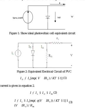
The photovoltaic cell converts the light energy intoelectrical energy depending on the irradiation of the sun andtemperature in the atmosphere. Basically PVC is a PNjunction diode [3] [4]. But in PN junction diode DCI ACsource is needed to work, but here light energy is used as asource to produce DC output. PVC is a current control sourcenot a voltage control source. The equivalent electrical circuitdiagram of PVC is shown in the Figure 2.
] 1 /
) [exp(
0
I V IR KT
ID S (1)
Therefore PVC output current is given in equation 2.
Sh D
L I I
I
I (2)
Sh S S L R IR V KT IR V q I I I / ) ( ] 1 / )) ( [exp( 0 (3)
Where
I
Dthe diode is current,R
sh is the shunt resistance,I
Lis the light generated current of solar array.Solar cell is basically a p-n junction fabricated in a thin wafer or layer of semiconductor. The electromagnetic radiation of solarenergy can be directly converted electricity through photovoltaic effect. Being exposed to the sunlight, photons with energy greater than the band-gap energy of the semiconductor are absorbed and create some electron-hole pairs proportional to the incident irradiation. Under the influence of the internal electric fields of the p-n junction, these carriers are swept apart and create a photocurrent which is directly proportional to solar insolation. PV system naturally exhibits a nonlinear I-V and P-V characteristics which vary with the radiant intensity and cell temperature.
III. MPPT ALGORITHM
Because of the lesser efficiency of photovoltaic array most of the energy, impacting over array gets wasted. The algorithm known as maximum power point tracking may be helpful to enhance the performance of solar panel. The MPPT algorithm works on principal of Thevenin, according which the power output of a circuit is maximum when impedance of circuit matches with the load of impedance. So now we have to match the impedance instead of tracking maximum power point.
There are different techniques used to track the maximum power point. Few of the most popular techniques are:
o Perturb and observe (hill climbing method)
o Incremental Conductance method
o Fractional short circuit current
o Fractional open circuit voltage
o Neural networks
o Fuzzy logic Perturb and observe
The P&O algorithm and “hill-climbing”, both names refer to the same algorithm depending on how it is implemented. The basic difference between these two is that Hill-climbing involves a deviation of the duty cycle of the power converter and in P&O anxiety on the operating voltage of the DC link between the PV array and the power converter takes place [3]. The deviation of duty cycle of the power converter is the modification of the voltage of DC link between the PV array and the power converter refer as Hill-climbing, so both names refer to the same technique. What should be the next perturbation is decided by considering the sign of the last perturbation and the sign of the last increment in the power.
The perturbation will remain in the same direction if power is incremented, and if power is decreased then next perturbation will be in the opposite direction. The process will be repeated until the point of maximum power will be reached. Then the operating point oscillates around the MPP.
Incremental conductance
The slope of the curve between power and voltage of PV module is the deciding factor in incremental conductance algorithm, if it is zero it shows point of MPP positive (negative) on the left of it and negative (positive) on the right.
∆V/∆P = 0 at the MPP
∆V/∆P > 0 on the left ∆V/∆P < 0 on the right
The change of MPP voltage is identified by comparing the change of the power to increment of the voltage of current curve.
Fractional short circuit current
Fractional short circuit current method states that the ratio between array voltage at maximum power VMPP to its open
circuit voltage VOC is nearly constant.
The constant K1 is having value between 0.71 to 0.78. Now the value of VMPP can be calculate by periodically
measuring VOC. This method is simple and cheap to implement but its efficiency is relatively low due to the utilization
of inaccurate values of the constant k1 in the computation of VMMP .
Photovoltaic cell
To convert the light energy supplied by sun the semiconductor solution is the photovoltaic cell it converts light energy to electrical energy by photovoltaic effect. The energy photons are available with light, if there energy is greater than the energy gap of atomic electronics, than the outer most electrons of atoms are get emitted because of the impact of these photon. These electrons get flow freely and cause current.
The construction of photovoltaic cell is similar as the construction of p-n junction diode. A photovoltaic cell is composed of two different layers of silicon one is P-type layer where negative ions are there with one less valence electron and other is N-type layer with positive ions with one extra valence electron. At the junction of these two layers extra electrons of N-layers get diffused with less electron space of P – layer and leave region with positive and negative ions only. This space is known as diffusion layer, the diffusion layer act as a protective layer and stops the transfer of electron across the junction when equilibrium is reached. When solar energy is imposed the energy of electrons available will increase and again transfer of electron get start. This will cause flow of current and convert solar energy into electric energy.
MatlabModelling of PV Array -
The equivalent circuit implementation of PV cell is shown in figure 3.
Figure 3: MATLB Model for PV array
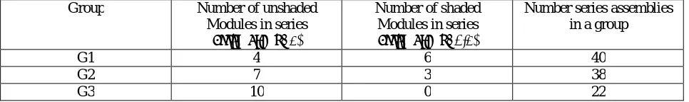
To simulate PV array first of all module of PV array is to be develop. For minimizing the shading effect the series connected PV modules with the same level insulation makes subassembly. To make large array several such series-connected subassemblies are series-connected where each will have same level of insulation. Series assemblies, whose shading pattern is similar form a group. Such various group are get connected in parallel to form a complete PV-array. The I-V and P-V characteristics of the various components of such PV array is given in Table 1.
Table 1: Shaded Pattern and Configuration
Group Number of unshaded
Modules in series
assembly (λ=1)
Number of shaded Modules in series
assembly (λ=0.1)
Number series assemblies in a group
G1 4 6 40
G2 7 3 38
Figure 4:PV Array
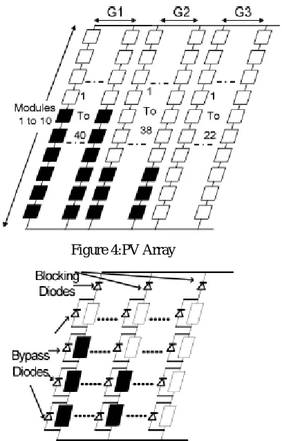
Figure 5: PV Array with bypass and blocking Diodes Effect of Bypass and Blocking Diodes on PV Characteristics
As mentioned in Figure 5 a PV array with bypass and blocking diodes connected in the array. It is important to note that the characteristics of and array with bypass and blocking diodes connected in the array. It is important to note that the characteristics of an array with bypass and blocking diodes differ from that of an array without these diodes.
IV. CONCLUSION
The shading effect is major cause of multiple peaks problem in PV-array system. The above given study is an attempt to discuss various cause and throes of this multiple peaks problem. In the Bypass and Blocking diode based MPPT scheme this problem can be overcome up to certain extent. The I-V and P-V characteristics of PV array having series and parallel combinations of modules. The study reveals that the magnitude of global peak depend on the pattern in which modules are connected and the pattern of shaded cells in each module.
REFERENCES
1. T. Noguchi, S. Togashi, and R. Nakamoto, “Short-current pulse-based maximum-power-point tracking method for multiple photovoltaic and converter module system,” IEEE Trans. Ind. Electron., vol. 49, no. 1, pp. 217–223, Feb. 2002.
2. Kun Ding, XinGaoBian, HaiHao Liu, and Tao Peng, “A MATLAB-Simulink-Based PV Module Model and Its Application Under Conditions of Nonuniform Irradiance”, IEEE Transactions on Energy Conversion, Vol. 27, No. 4, December 2012.
3. Salas, E. Olias, A. Barrado, and A. Lazaro, “Review of the maximum power point tracking algorithms for stand-alone photovoltaic systems,” Sol. Energy Mater. Sol. Cells, vol. 90, no. 11, pp. 1555–1578, Jul. 2006.
5. N. Fernia, G. Petrone, G. Spagnuolo, andM. Vitelli, “Optimization of perturb and observe maximum power point tracking method,” IEEETrans. Power Electron., vol. 20, no. 4, pp. 963–973, Jul. 2005.
6. T. Esram, J. W. Kimball, P. T. Krein, P. L. Chapman, and P. Midya, “Dynamic maximum power point tracking of photovoltaic arrays using ripple correlation control,” IEEE Trans. Power Electron., vol. 21, no. 5, pp. 1282–1291, Sep. 2006.
7. C. Dorofte, U. Borup, and F. Blaabjerg, “A combined two-method MPPT control scheme for grid-connected photovoltaic systems,” in Proc. Eur. Conf. Power Electron. Appl., Sep. 11–14, 2005, pp. 1–10.
8. K. H. Hussein and I. Muta, “Maximum photovoltaic power tracking: An algorithm for rapidly changing atmospheric conditions,” Proc.Inst. Electr. Eng.—Generation, Transmission Distribution, vol. 142, no. 1, pp. 59–64,Jan. 1995.
9. D. Sera, T. Kerekes, R. Teodorescu, and F. Blaabjerg, “Improved MPPT method for rapidly changing environmental conditions,” in Proc. IEEE Int. Ind. Electron. Symp., Jul. 2006, vol. 2, pp. 1420–1425.
10. N. Kasa, T. Iida, and H. Iwamoto, “Maximum power point tracking with capacitor identifier for photovoltaic power system,” Proc. Inst.Electr. Eng.—Electr. Power Appl., vol. 147, no. 6, pp. 497–502, Nov. 2000.
11. N. Kasa, T. Iida, and L. Chen, “Flyback inverter controlled by sensorless current MPPT for photovoltaic power system,” IEEETrans. Ind. Electron., vol. 52, no. 4, pp. 1145–1152, Aug. 2005.