Exploiting Safe Error based Leakage of RFID
Authentication Protocol using Hardware Trojan
Horse
Krishna Bagadia, Urbi Chatterjee, Debapriya Basu Roy, Debdeep Mukhopadhyay, and Rajat Subhra Chakraborty
[email protected],{urbi.chatterjee, debu.basu.roy, debdeep, rschakraborty}@cse.iitkgp.ernet.in Department of Computer Science and Engineering, Indian Institute of Technology Kharagpur
Abstract—Radio-Frequency Identification tags are used for several applications requiring authentication mechanisms, which if subverted can lead to dire consequences. Many of these devices are based on low-cost Integrated Circuits which are designed in off-shore fabrication facilities and thus raising concerns about their trust. Recently, a lightweight entity authentication protocol called LCMQ was proposed, which is based on Learning Parity with Noise, Circulant Matrix, and Multivariate Quadratic problems. This protocol was proven to be secure against Man-in-the-middle attack and cipher-text only attacks. In this paper, we show that in the standard setting, although the authentication
uses two m bit keys, K1 and K2, knowledge of only K2 is
sufficient to forge the authentication. Based on this observation, we design a stealthy malicious modification to the circuitry based on the idea of Safe-errors to leak K2 and thus can be used to forge the entire authentication mechanism. We develop a Field Programmable Gate Array prototype of the design which is extremely lightweight and can be implemented using four Lookup tables.
I. INTRODUCTION
Radio Frequency Identification (RFID) tag is the vital component of solutions to many recent problems, ranging from supply chain management to anti-counterfeiting. E-passports and RFID enabled bank notes are mere examples of a set of authentication and tracking applications where RFIDs are used routinely. As more and more organizations have accepted it as an integral part of almost every possible household gadget, they have started occupying a substantial part in this framework and therefore several lightweight authentication protocols and algorithms have been proposed for these low-cost, strictly resource-constrained devices.
Manufacturing of RFID tags is usually outsourced to poten-tially untrusted remote electronic manufacturing facilities. Any modification in the implementation of tag can lead to unau-thorized access, clandestine scanning, clandestine tracking, skimming and cloning which could prove to lethal in case of e-passports and RFID enabled bank notes. They could be used to track the foot prints of an eminent personality or as an easy entry into a nation. Hardware Trojan Horses (HTHs) are surreptitious-by-design, malicious modifications to integrated circuits which have the capability to evade traditional post-manufacturing testing, and once deployed, can cause disastrous functional failure or information leakage ( [1], [2], [3]). Once a HTH-infected circuit is deployed, usually they cannot be
neutralized by any hardware or software updates. Hence, they are regarded as one of the foremost threats to security and privacy.
HTHs have been leveraged in multiple works in the past to launch side-channel attack [1] and fault attack ( [2], [3]) on hardware implementation of cryptographic algorithms such as Advanced Encryption Standard(AES), leading to the recovery of the secret key. In this paper, we focus on lightweight authentication protocols which are rigourously analysed for RFID applications, and their vulnerability to HTH-induced fault attack. In [4], Avoine et al. have provided a survey of the most prominent ultralightweight authentication protocols for RFID tags and their common flaws. Among them, one of the significant family of protocols had its origins in ”HB” which is a secure identification scheme based on Learning Parity with Noise (LPN) problem designed in [5] by Hopper and Blum. Subsequently several HB-like protocols such as HB+ [6], GHB# [7], LAPIN [8], LCMQ [9] have been pro-posed. Several cryptanalysis techniques proposed in [10], [11] have successfully attacked most of these HB-family protocols. Moreover, researchers have also started to realize the impact of side channel based attacks on the physical implementation of these protocols. In [12], Carrijo et al. proposed a fault analytic model which can lead to a cogent attack against HB-like protocols. Similarly in [13], Gaspar et al. illustrated a DPA-like attack on the hardware implementation of Masked Lapin algo-rithm. In 2013, Li et al. presented a novel entity authentication protocol titled LCMQ which is not direct descendant of HB protocol, rather a consolidation ofLPN,Circulant Matrixand Multivariate Quadratic (MQ) problem that has been proved to be secure against mathematical cryptanalysis. In this paper, our two major contributions are:
• We first propose a lightweight hardware architecture of RFID tag involved in the LCMQ authentication proto-col.To the best of our knowledge, no hardware imple-mentation based analysis of LCMQ protocol has been reported so far.
• Secondly, we demonstrate the use of HTH to exploit
an attack in which a stuck-at-0 or stuck-at-1 fault induced at an internal state-bit helps to reveal the actual state-bit value through analysis of the obtained output [14].
This paper is organized as follows. In Section II, we have briefly presented the mathematical background necessary to understand the LCMQ protocol. Its hardware architecture have been described in Section III. Next, in Section IV, we have presented the designed HTH and described how it is leveraged to launch the key leakage safe error attack on the protocol and the implementation and attack results are presented in Section V. Finally the paper has been concluded in Section VI.
II. BACKGROUND
In this section we provide the basics of the LPN problem, Circulant Matrices, Multivariate Quadratic Polynomials and finally, the LCMQ protocol.
A. LPN Problem
Suppose both the tag and the reader share an already agreed
m-bit keyKfor the successive authentication rounds. Initially, the reader randomly selects a set of m-bit binary vectors
a0,a1,...,al−1 and sends them as a challenge to the tag. To
generate the response, the tag computeszi =<ai,K>for all
i∈ {0,· · ·, l−1}, where<ai,K>denotes the dot product modulo-2 ofaiandK. Now, the reader will only accepts the tag if<ai,K>=zi. But this scheme is simply vulnerable as
an adversary can eavesdropmlinearly independent challenge-response pairs(ai, zi)and retrieve the secret keyKby solving
a linear system of equations modulo-2. But the determination of the key becomes difficult in the presence of noise. Hence the LPN problem can be defined as:
Definition 1: (LPN Problem) Let A be a random (l ×m) -binary matrix, K be a random m-bit vector, ∈ (0,1
2) be a noise parameter, and V be a random l-bit vector such that Hwt(V)≤×l. where Hwt(V)denotes theHamming Weight of a binary vectorV, i.e., the number of bits which are 1 in a binary vectorV. GivenA, , andz=< A· Kt>
⊕Vt, find a
k-bit vectoryt such that Hwt(< A
·yt >
⊕z)≤×l. This problem is proven to be NP-Hard [15] and the key length
m and the noise level decides the security of the problem instances. As stated in [9], for 80-bit security,mandare set to 512 and 0.25.
B. Circulant-P2 Matrix
Definition 2: (Square Circulant Matrix) A square circulant matrix M of order (m×m) is a matrix with first row =
[α0 α1 . . . αm−1] and the next rows are generated by right circular rotation of the previous row.
Now, as given in [9], the circulant-P2 matrix can be defined as:
Definition 3: (Circulant-P2 Matrix) Givenn < m, a circulant-P2 matrix is an(m×m)square circulant matrix, or an(n×m)
landscape circulant matrix, or an (m×n) portrait circulant matrix, satisfying the below criteria.
1) It must be a binary matrix.
b∈R{0,1}m
v∈R{{0,1}n| Pr[vi=1] =ǫ, where 0≤i≤n−1}
y=b·C[m×n]
k1 ⊕v
r∈R{0,1}m−n−1 Tag(k1,k2)
whereθ∈(ǫn,n/2)
Calculates: (y||r) =Decode(z,k2⊕a)
Accepts the tag if Reader(K1,k2)
a
a∈RE
b,z
z= (y||r)·C[n×m] k2⊕a
Hwt((b·C[m×n]
k1 )⊕y)≤θ
ˆ
Fig. 1. The LCMQ protocol.
2) m is a prime number such that that 2 is a primitive element of the finite field Fm. . Here, m is defined as
aP2 number.
3) No row vector and column vector of a Circulant-P2 matrix can be all zeroes or all ones.
It is to be noted that all row vectors in a landscape circulant matrix are linearly independent to each other. Similarly, all column vectors in a portrait circulant matrix are linearly independent.
C. LCMQ Problem
LetE = {a|a∈ {{0,1}m
r{{0}m, {1}m}} andHwt(a) is
even} and given an m-bit binary vector α, Cα denotes the
square circulant matrix of order m×mwith first row as α. Then we can define LCMQ problem as below.
Definition 4: (LCMQ problem) Let m be a P2 number,
n < m, ∈(0,1
2) be the noise parameter,K1 ∈R {0,1}m,
parity of Hamming weight of K1 is publicly known and
K2∈RE. Givenlpairs of(bi,zi= (((bi·C
[m×n]
K1 )⊕vi)||ri)·
CK[(m−1)×m]
2 ), ∀i ∈ {0,· · · , l−1}, where bi ∈R {0,1}
m,
Pr[vi[j] = 1]=, Pr[vi[j] = 0]= (1−)∀0≤j≤n−1 and
ri∈R{0,1}m−n−1, determineK1 andK2.
If we considern=m−1 and there is no noise in the system, then this problem reduces to findingK1 andK2 such that:
(bi∈R{0,1}m,z0i= (bi·C [m×n] K1 )·C
[(m−1)×m]
K2 )
As shown in [9], this problem is an instance of multivariate quadratic (MQ) problem in2(m−1)variants. This is another problem known to be NP-complete [16] and stated as below: Definition 5: (MQ Problem) Given a system ofdmultivariate quadratic equations in t variables over a finite field, find a valid solution satisfying all equations.
D. The LCMQ Protocol
Let parameterθ∈(×n,n2) be a threshold value, similar to the LPN problem. The steps for the LCMQ Protocol are as follows:
• Both Tag and the Reader shares two m-bit secret keys
K1 andK2. For80-bit security, the authors proposedm
to be163 bit in [9].
• First the reader selects anm-bit random binary vectora
from the set E and sends it to the tag.
• The tag randomly selects anm-bit binary vectorb and
• Then it generates the circulant matrix CK[m×n]
1 using K1
as the first row and multiplies with b. The final n-bit output is XOR-ed with vand thusy is generated.
• Next, it chooses another random variablerof length(m− n−1)and appends it toy. This is finally multiplied with the matrixCK[(m−1)×m]
2⊕a to producez.
• The tag then sends (b,z) to the reader.
• The reader first decodes y||rfrom zand K2⊕a using the algorithm described in [9]. Finally it checks whether the Hamming weight of ((b·CK1)⊕y) is less than or
equal to the thresholdθor not. If yes, then it accepts the tag.
Observation: In this paper, we make a major observation on the protocol, which to the best of our knowledge was not reported earlier: the recovery of K2 is sufficient for the adversary to enable successful authentication attempts. Suppose that the adversary is able to monitor the communica-tion network between a tag and a reader. She eavesdrops to ob-tain a tripletac,bc,zcthat leads to a successful authentication as shown in Fig. 1. Suppose, she also knows the correct key
K2. Using this, she can calculateyc=Dec(zc,K2⊕a).Dec
is the decryption algorithm where polynomial multiplication of zc andK2⊕a−1 modulo xm+ 1is used to calculateyc
as mentioned in [9]. Now, the adversary interacts with the reader. Reader sends her the challenge, let it beaw. Adversary calculates zw = yc ·CK2⊕aw and sends zw,bc over the
network. The reader decrypts using the Dec algorithm and obtains yc which was already authenticated by the reader for bc. Hence, if the adversary obtains the key K2, it can impersonate as a valid tag, without even having the knowledge of key K1. Hence, an HTH is designed in the subsequent sections to exploit the safe error and obtain this key K2. This observation plays a crucial role in the design of HTH described in Section IV, but before that, we will explain the hardware architecture of the tag in case of LCMQ protocol.
III. ARCHITECTURE OF THELCMQ HARDWARE IMPLEMENTATION
As shown in Fig. 2, the components involved in the hardware architecture of the tag are m-bit random number generator (RN G),(m−n−1)-bit registerReg r,m-bit registerReg b,
n-bit registerReg vfor the variablesr,b,vrespectively. The two blocksB1,B2, each consists of an Inner Product Module (IP), a 2×1 multiplexer, 1 right shift module (RS) and 1 shift register (SR). Block B2, also contains a permutation module which is used to convert the initial input keyK2⊕a
into the first column of circulant matrix CK[(m−1)×m]
2 . Since,
the random numbers are needed at different stages in an authentication round, control signals load r, load b, load v
are provided to load values into Reg r, Reg b, Reg v re-spectively. An Finite State Machine (FSM) is also designed to control the clock and other control signals. The various components are explained as follows.
A. RN G
The RN G module produces an m-bit random number using an 32-bit LFSR. This LFSR is run for d[m/32e cycles to produce an m-bit output. An LFSR-based RNG might not provide sufficient entropy in a practical situation; however, we do not base our attack on the source of randomness, we use an LFSR as a source of entropy required to imitate the tag.
B. Generate v
Generation ofn-bitvis based on Bernoulli trials with param-eterη. An7-bit binary random number simulates1-bit ofv. If this number is less thanη∗128/100, then the corresponding bit is 1, otherwise 0. Therefore, anm-bit random number can generate dm/7e bits of v. Hence, total number of random numbers required areldm/n7em.
C. Matrix Multiplication
Typical matrix multiplication requires us to store the whole matrix, but it is almost impractical for a RFID tag because of sever area constraints. According to [4], an RFID protocol must not take more than 1000 Lookup Tables (LUTs) for a Field Programmable Gate Array (FPGA) implementation. To solve this problem, we exploit the property of circulant matrices to perform the matrix multiplication with less mem-ory and a relatively small computational overhead. There are two multiplication blocksB1andB2. The first multiplication block B1, is for the multiplication of a portrait circulant matrix with a vector,(b·CK[m×n]
1 ). Similarly, the second block
B2, is used to calculate the multiplication of a landscape circulant matrix with a vector,((y||r·CK[(m−1)×m]
2⊕a )). InB1,
b along with secret key K1 are inputs. Multiplexer along with the right shift module imitates ith column in ith clock
cycle. IP is the module which calculates the inner product modulo-2 of its inputs, thus in ith clock cycle, it calculates
the < b, CK[m1×,in] > whereCK[m×n]
1,i is the i
th column of the
circulant matrix CK[m×n]
1 . The output of IP is stored in a shift
register which does a left circular shift at every clock cycle. Initially, sel signal is 0, which inputs the secret key as it is. Afterwards,selis 1, which inputs a right circular shifted value of the previous output. These simulate the behavior of the circulant matrixCK[m×n]
1 . It requiresnclock cycles to generate
the n-bit vector. Similarly, y||r, and K2 are inputs to B2
which calculates the value ofz.
D. Overall Hardware Module Operation
Initially, the RN Ggenerates am-bit random number that is loaded intoReg b. This binary vector is then fed into block
B1. In the meanwhile, the modulegenerate v generates the random vector v following a Bernoulli distribution. After
n clock cycles, the output of block B1, is XOR-ed with
Reg v to produce y which similarly calculates z after its concatenation withrand multiplication of concatenated result withCK[(m−1)×m]
RNG
Reg r Reg b
. . .
v
Register
U
(m−n−1)bits
Reg v seed enable
K2out[0] load b load v clk
clk
Shift Generate v
m bits b
n bits NI
N E R
P R O D U
T C B1
K1
clk
Sel
Right Shift
r
y XOR
P E R M
T A T I O N
Sel
(θ0, θm−1, θm−2, ..., θ1) T C U D O R P R E N NI
append(y||r)
a
(θ0, θ1, θ2...θm−1)
clk Right Shift B2
a[0:6]
Trigger
Comparator
K2in[80]
K2in[0]
K2in[1:79]
K2out[81:m−1]append
K2out[80]
Counter
Actual Design
load r
K2in M
U X
M U X
M U X
M U X
Implanted Trojan
K2in[81:m−1]) K2out[80]|| K2in[1:79]|| (K2out[0]|| m bits
m bits
a[7]
K2
m bits XOR m bits
seed
load b clk
Counter load r
enable
load v Trigger
Shift Register
clk
z b
m bits FSM
1′b1
Fig. 2. Architecture of LCMQ - tag.
IV. HTH INDUCEDSAFEERRORATTACK ON THELCMQ PROTOCOL
An HTH design usually comprises of two phases:Payloadand Trigger. Payload is the portion of the HTH circuitry that is responsible for inducing the functional failure or information leakage, while the trigger is the portion of the HTH used to activate the HTH. In an effective HTH, payload should have very low power overhead, ideally zero. Moreover, the HTH should be rarely triggered so that it can easily pass the verification test done after manufacturing of the chips or circuits. In this section, we mainly focus on the design of payload, but before that, we give a brief overview of the adversarial model and the trigger condition of HTH.
A. Adversary Model
As shown in [2], nexus between two or more stages of RFID manufacturing and deployment can be easily exploited in order to launch an impersonation of tag attack. In our adversary model, we assume that the adversary is herself the malicious designer and maintains a malicious nexus with a personnel at a fabrication facility of the RFID tags. It is this personnel in the fabrication facility who injects a HTH designed by the adversary in order to reveal secret information to her. Hence,
we can say that only these persons know the mechanism to activate the HTH.
As the HTH in an Intellectual Property (IP) core renders com-parison with a golden model extremely difficult, it is highly unlikely to detect the HTH using Side Channel Analysis (SCA) [17]. However, one must ensure that the gate count difference between actual design and the infected design should not be very high. In order to ensure this, we implement the HTH using the LUTs on the FPGAs directly, which provides almost negligible overhead in terms of power as well as gate. The adversary uses the HTH to retrieve the key K2 and then successfully impersonates according to the observation mentioned earlier. The triggering of HTH will be explained in the next subsection.
B. Activation of HTH
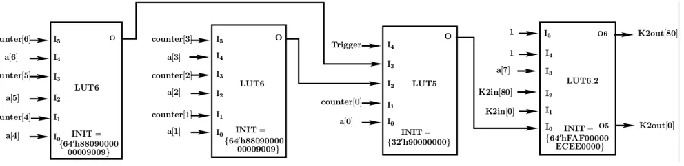
Fig. 3. LUT Diagram of Implanted HTH in architecture wherem= 163.
low as the protocol is lightweight. Since, many RFID tags that are deployed for security purposes contain some sort of sensor, external triggering is feasible. For example, an active tag usually has a temperature sensor which monitors the tem-perature [18]. Let us assume that they have an ideal working range from 0◦C to 30◦C and then raising the temperature to
35◦C should trigger the Trojan without comprising with other
security concerns like reset feature of tag etc as shown in [17]. Since, this rests entirely in the hands of adversary, it is rarely activated in the testing phase, making it utmost difficult to detect making the attack extremely effective.
Once the HTH is activated, the circuitry then modifies some bits of the register by producing a safe error which will be discussed next.
C. Payload of HTH
We present an ultra-low hardware footprint HTH which occu-pies only 4 LUTs. Since, we are trying to obtain the secret key K2, it is necessary for us to inject a safe error in all the m bits. However, if we add a multiplexer separately for all the bits, then that would lead to an linear increase in the overhead. In order to counter act this, we exploit the property of circulant matrices. Since, the input key is right shifted at each clock cycle, as explained in Section III-C, a safe error induced at1stbit of right shift register in tth clock cycle is equivalent in inducing a safe error in tth bit of initial input key. We exploit this to induce safe error in all bits of input key by inducing safe error at a single position of right shift register in different clock cycles.
The malicious circuit is shown in the Fig.2. The whole malicious circuit can be incorporated in the design using only 4 LUT’s. The truth table for inputs a[7 : 0], counter,
K2in[0] and K2in[80] to the malicious circuit in the Fig 2 was constructed and mapped to LUTs available in Virtex-5 FPGA board. The LUT diagram along with the INIT value is shown in Fig 3. We will demonstrate the payload mechanism on a protocol architecture where the P2 number is 163.
D. Low Overhead Implementation of HTH on Xilinx FPGA
In our design, the adversary does not need to externally give bit position at which safe error would be introduced. Let
counter be an 8-bit binary number that counts the163 clock cycles in B2 and a[7 : 0] corresponds to last 8-bits of a, the challenge send by the reader. Note that counter is a part
of the architecture of the tag and is not a modification of HTH. These two 8-bit numbers are compared in order to introduce a safe error at a particular cycle, thus removing the need of externally sending the target bit position. Once, the trigger is activated, the HTH synchronizes in the next authentication round. Depending upon the value of the last 8-bits ofavector, the HTH introduces a safe error by setting the bit toVdd, either at the1st bit ofK2in or 80thbit of it.
This mechanism can be explained using the LUT diagram in Fig 3. In case of 6-input LUT6 module (as available inXilinx Virtex-5and later series of FPGAs), the output will be 1 when
I5=I4, I3 =I2, I1 =I0. Therefore, the two 1-output LUT6 compares the last 6 bits of counter anda. LUT5 outputs 1 only whenI1 =I0, I2 =I3 = 1, I4 = 1. Hence, these three LUT’s combined introduces a fault in the clock cycle whose value equals a[6 : 0] when the HTH is triggered. In case of 2-output LUT6 ifa[7] = 0andI0= 1, the output O6 is same asK2in[80] and O5 is 1, whereas ifa[7] = 1andI0= 1, O6 is 1 and O5 is same asK2in[0]. In all other cases, the value
of K2in[0] andK2in[80] remains unmodified. After this the
HTH sleeps again waiting for an external triggering to take place. Hence, the 4 LUT’s together, depending upon the value of a[7 : 0] will inject a safe error into either the80th bit or
0thbit in the clock cycle whose value is equal toa[6 : 0]. It is
equivalent to inducing a safe error ina[6 : 0]thbit ifa[7] = 0
and ina[6 : 0]+80thbit ifa[7] = 1. Note that the safe error at
K2[0]andK2[80]is introduced in the0thclock cycle, i.e. at
the starting of the multiplication. After inducing the stuck-at-fault, if the authentication succeeds then the adversary infers that the corresponding bit was 1, otherwise that corresponding bit 0.
In the design, two 2×1 multiplexers are required because at least half of the bits ofzshould be faulty in order to correctly estimate the value of that bit. Since, the adversary has control over the network, she knows the value of a being sent and depending upon the result of authentication, she knows that corresponding bit. Also, the value ofa[7 : 0]rests in the hands of reader, and each bit ofawhen considered random is equally likely to produce all the values between 0to255. Hence, the adversary will be able to obtain all the bits of keyK2.
V. IMPLEMENTATION ANDRESULTS
TABLE I
HARDWAREOVERHEAD
Components Original
Design Design with HTH
Increase in Number %
LUT 714 717 0.4
SliceRegs 1507 1505 -0.13
Slices 589 589 0.0
TABLE II
POWER ANDTIMINGOVERHEAD
Overhead Original Design Design with HTH Increase inNumber %
Power 0.539 W 0.538 W -0.18 Timing 3.789 ns 3.794 ns 0.13
using Verilog HDL and executed on Virtex-5 FPGA board. The results are shown for 80-bit security with parameter values
m = 163, n = 162, θ = 18, η = 0.08. The designs were synthesized and implemented usingXilinx ISE 14.5, and simu-lated usingXilinx Isim. The power estimation of the circuit was carried out usingXilinx XPower Analyzerand delay estimation using Xilinx Timing Analyzer. Table I shows the comparison between the golden design and the overhead of the HTH circuit. Table II illustrate the percentage increase/decrease in the total power consumption and the critical path delays of the design before and after Trojan insertion. We have assigned theLUT combiningsub- property of theMap property to Area in the CAD software tool considering the reduced size of RFID tags. As shown in the result, two registers are reduced owing to the replacement of two registers byK2out[0] K2out[80]. Similarly, due to less switching activity, the power consumption has also reduced. Additionally, the HTH circuit requires4-LUTs, but due to the circuit’s optimization process, the actual implementation requires additional 3-LUTs only. Thus the overhead of the HTH is indeed minimal to evade standard detection techniques.
Theoretically163rounds of authentication should be sufficient to obtain all the163bits of the secret keyK2. But in simulated scenarios, the number of authentication rounds required were expected to be around 211. This happens because the value of a[7 : 0] is equally likely to produce all the bits between0
to 255. Hence, there will be some cases where the value of
a[7 : 0] will be greater than 163 and hence, will not result in information leakage. But since, the adversary controls the triggering of the HTH, this does not decrease the potential of the attack.
VI. CONCLUSION
This paper addresses the issue of exploiting Circulant Matrix property to insert a stealthy HTH that could use safe error to obtain all secret keys, thus making impersonation of tag viable. First, we made an key observation that in an LCMQ protocol an attacker can impersonate without the knowledge of key K1, thus motivating a HTH designer to just target key K2. Subsequently, we gave an effective and efficient architecture of tag part of the LCMQ problem. We provided an ultra-lightweight HTH design which can induce safe errors surreptitiously to leak K2 potentially. We summed up by providing the hardware implementation of the LCMQ protocol and the design overheads, which confirm that the HTH in this
type of setup is viable and efficient. Finally, this work re-establishes the importance of robustness again HTHs and other implementation-specific vulnerabilities for secure protocol im-plementations.
REFERENCES
[1] L. Lin, W. Burleson, and C. Paar, “MOLES: malicious off-chip leak-age enabled by side-channels,” in 2009 International Conference on Computer-Aided Design, ICCAD 2009, San Jose, CA, USA, November 2-5, 2009, 2009, pp. 117–122.
[2] S. Ali, R. S. Chakraborty, D. Mukhopadhyay, and S. Bhunia, “Multi-level attacks: An emerging security concern for cryptographic hardware,” in Design, Automation and Test in Europe, DATE 2011, Grenoble, France, March 14-18, 2011, 2011, pp. 1176–1179.
[3] A. P. Johnson, S. Saha, R. S. Chakraborty, D. Mukhopadhyay, and S. G¨oren, “Fault attack on AES via hardware trojan insertion by dynamic partial reconfiguration of FPGA over ethernet,” inProceedings of the 9th Workshop on Embedded Systems Security, WESS ’14, New Delhi, India, October 17, 2014, 2014, pp. 1:1–1:8.
[4] G. Avoine, X. Carpent, and J. Hernandez-Castro, “Pitfalls in ultra-lightweight authentication protocol designs,”IEEE Trans. Mob. Comput., vol. 15, no. 9, pp. 2317–2332, 2016.
[5] N. J. Hopper and M. Blum, “Secure human identification protocols,” inAdvances in Cryptology - ASIACRYPT 2001, 7th International Con-ference on the Theory and Application of Cryptology and Information Security, Gold Coast, Australia, December 9-13, 2001, Proceedings, 2001, pp. 52–66.
[6] A. Juels and S. A. Weis, “Authenticating pervasive devices with human protocols,” inAdvances in Cryptology - CRYPTO 2005: 25th Annual International Cryptology Conference, Santa Barbara, California, USA, August 14-18, 2005, Proceedings, 2005, pp. 293–308.
[7] P. Rizomiliotis and S. Gritzalis, “GHB #: A provably secure hb-like lightweight authentication protocol,” inApplied Cryptography and Net-work Security - 10th International Conference, ACNS 2012, Singapore, June 26-29, 2012. Proceedings, 2012, pp. 489–506.
[8] S. Heyse, E. Kiltz, V. Lyubashevsky, C. Paar, and K. Pietrzak, “Lapin: An efficient authentication protocol based on ring-lpn,” inFast Software Encryption - 19th International Workshop, FSE 2012, Washington, DC, USA, March 19-21, 2012. Revised Selected Papers, 2012, pp. 346–365. [9] Z. Li, G. Gong, and Z. Qin, “Secure and efficient LCMQ entity authentication protocol,”IEEE Trans. Information Theory, vol. 59, no. 6, pp. 4042–4054, 2013.
[10] H. Gilbert, M. J. B. Robshaw, and H. Sibert, “An active attack against HB+ - A provably secure lightweight authentication protocol,” IACR Cryptology ePrint Archive, vol. 2005, p. 237, 2005.
[11] H. Gilbert, M. J. B. Robshaw, and Y. Seurin, “Good variants of hb+ are hard to find,” in Financial Cryptography and Data Security, 12th International Conference, FC 2008, Cozumel, Mexico, January 28-31, 2008, Revised Selected Papers, 2008, pp. 156–170.
[12] J. Carrijo, R. Tonicelli, and A. C. A. Nascimento, “A fault analytic method against hb+,” IEICE Transactions, vol. 94-A, no. 2, pp. 855– 859, 2011.
[13] L. Gaspar, G. Leurent, and F. Standaert, “Hardware implementation and side-channel analysis of lapin,” inTopics in Cryptology CTRSA 2014 -The Cryptographer’s Track at the RSA Conference 2014, San Francisco, CA, USA, February 25-28, 2014. Proceedings, 2014, pp. 206–226. [14] S. Yen and M. Joye, “Checking before output may not be enough against
fault-based cryptanalysis,”IEEE Trans. Computers, vol. 49, no. 9, pp. 967–970, 2000.
[15] E. R. Berlekamp, R. J. McEliece, and H. C. A. van Tilborg, “On the inherent intractability of certain coding problems (corresp.),”IEEE Trans. Information Theory, vol. 24, no. 3, pp. 384–386, 1978. [16] M. R. Garey and D. S. Johnson,Computers and Intractability; A Guide
to the Theory of NP-Completeness. New York, NY, USA: W. H. Freeman & Co., 1990.
[17] D. B. Roy, S. Bhasin, S. Guilley, J. Danger, D. Mukhopadhyay, X. T. Ngo, and Z. Najm, “Reconfigurable LUT: A double edged sword for security-critical applications,” in Security, Privacy, and Applied Cryptography Engineering - 5th International Conference, SPACE 2015, Jaipur, India, October 3-7, 2015, Proceedings, 2015, pp. 248–268. [18] Sensor-enabled RFID tag handbook, 2008. [Online]. Available: http: