Black-Box Garbled RAM
Sanjam Garg∗ Steve Lu† Rafail Ostrovsky‡
Abstract
Garbled RAM, introduced by Lu and Ostrovsky, enables the task of garbling a RAM (Random Access Machine) program directly, there by avoiding the inefficient process of first converting it into a circuit. Garbled RAM can be seen as a RAM analogue of Yao’s garbled circuit construction, except that known realizations of Garbled RAM make non-black-box use of the underlying cryptographic primitives.
In this paper we remove this limitation and provide the first black-box construction of Garbled RAM with polylogarithmic overhead. Our scheme allows for garbling multiple RAM programs being executed on a persistent database and its security is based only on the existence of one-way functions. We also obtain the first secure RAM computation protocol that is both constant round and makes only black-box use of one-way functions in the OT-hybrid model.
∗
University of California, Berkeley. Computer Science [email protected]. Supported by NSF CRII Award 1464397.
†
University of California, Los Angeles. Department of Computer [email protected] ‡
1
Introduction
Alice wants to store a large private databaseD on the cloud in an encrypted form. Subsequently, Alice wants the cloud to be able to compute and learn the output of arbitrary dynamically chosen private pro-gramsP1, P2, . . .on private inputsx1, x2, . . .and the previously stored dataset, which gets updated as these programs are executed. Can we do this?
The above problem is a special case of the general problem of secure computation [Yao82,GMW87]. In the past three decades of work, both theoretical and practical improvements have been pushing the limits of the overall efficiency of such schemes. However most of these constructions work only for circuits and securely computing a RAM program involves the inefficient process of first converting it into a circuit. For example, Yao’s approach requires that the program be first converted to a circuit — the size of which will need to grow at least with the size of the input. Hence, in the example above, for each program that Alice wants the cloud to compute, it will need to send a message that grows with the size of the database. Using fully homomorphic encryption [Gen09] we can reduce the size of Alice’s message, but the cloud still needs to compute on the entire encrypted database. Consequently the work of the cloud still grows with the size of the database. These solutions can be prohibitive for various applications. For example, in the case of binary search the size of the database can be exponentially larger than execution path of the insecure solution. In other words security comes at the cost of a exponential overhead. We note that additionally even in settings where the size of the database is small, generic transformations from RAM programs with running timeT
result in a circuit of sizeO(T3logT)[CR73,PF79], which can be prohibitively inefficient.
Secure computation for RAM programs. Motivated by the above considerations, various secure com-putation techniques that work directly for RAM programs have been developed. However all known results have interesting theoretical bottlenecks that influences efficiency, either in terms ofround complexityor in theirnon-black-boxuse of cryptographic primitives.
- For instance, Ostrovsky and Shoup [OS97] show how general secure RAM computation can be done using oblivious RAM techniques [Gol87, Ost90, GO96]. Subsequently, Gordon et al. [GKK+12] demonstrated an efficient realization based on specialized number-theoretic protocols. In follow up works, significant asymptotic and practical efficiency improvements have been obtained by Lu and Ostrovsky [LO13a] and by Wang et al. [WHC+14]). However, all these works require round com-plexity on the order of the running time of the program.
- In another recent line of work [LO13b,GHL+14,GLOS14], positive results on round efficient secure computation for RAM programs have been achieved. However all these constructions are inherently non-black-box in their use of cryptographic primitives.1 These improvements are obtained by realiz-ing the notion of garbled random-access machines (garbled RAMs) [LO13b] as a method to garble RAM programs directly, a RAM analogue of Yao’s garbled circuits [Yao82].
In particular, we use the notationPD(x)to denote the execution of some RAM programP on input
x with initial memoryD. A garbled RAM scheme should provide a mechanism to garble the data
Dinto garbled dataD˜, the programP into garbled programP˜ and the inputxinto garbled inputx˜ such that givenD,˜ P˜andx˜allows for computingPD(x)and nothing more. Furthermore, up to only poly-logarithmic factors in the running time of the RAMPD(x) and the size ofD, we require that the size of garbled dataD˜ is proportional only to the size of dataD, the size of the garbled input ˜
xis proportional only to that ofxand the size and the evaluation time of the garbled programP˜ is proportional only to the running time of the RAMPD(x).
1
Starting with Impagliazzo-Rudich [IR90,IR89], researchers have been very interested in realizing cryp-tographic goals making just black-box use of underlying primitive. It has been the topic of many important recent works in cryptography [IKLP06,PW09,Wee10,GLOV12,GOSV14]. On the other hand, the problem of realizing black-box construction for various primitive is still open, e.g. multi-statement non-interactive zero-knowledge [BFM88, FLS99, GOS06] and oblivious transfer extension [Bea96].2 From a complex-ity perspective, black-box constructions are very appealing as they often lead to conceptually simpler and qualitatively more efficient constructions.3
Motivated by low round complexity and black-box constructions, in this work, we ask if we can achieve the best of both worlds. In particular:
Can we construct garbled RAM programs with only polylogarithmic overhead making only black-box use of cryptographic primitives?
1.1 Our Results
In this paper, we provide the first construction of a fully black-box garbled RAM, i.e. both the construction and the security reduction make only black-box use of underlying cryptograhpic primitives (one-way func-tions). The security of our construction is based on the existence of one-way functions alone. We state this as our main theorem:
Main Theorem (Informal). Assuming only the existence of one-way functions, there exists a secure black-boxgarbled RAM scheme, where the size of the garbled database is O˜(|D|), size of the garbled input is
˜
O(|x|)and the size of the garbled program and its evaluation time isO˜(T)whereT is the running time of programP. HereO˜(·) ignorespoly(logT,log|D|, κ) factors whereκ is the security parameter4. Since garbled RAM implies one-way functions, this can be stated as an equivalence of primitives.
Just as in previous works on garbled RAM [LO13b,GHL+14,GLOS14], our construction allows for maintaining persistent database across execution of multiple programs on the garbled memory. Also as in [GKP+13,LO13b,GHL+14,GLOS14], if one is willing to disclose the exact running time of a specific execution, then the running time of a garbled RAM computation can be made input specific which could be much faster than the worst-case running time.
Secure RAM computation. We also obtain the first one-round secure computation protocol for RAM programs that makes only black-box use cryptography in the OT-hybrid model. A very unique feature of this construction is that it allows for asymmetric load in terms of storage costs, i.e., only one party stores the encrypted database. To the best of our knowledge no previous solutions allowed for an encrypted database based of private information of both parties to be stored on just one party, and yet allow secure RAM computation on it using black-box methods alone. This makes our constructions particularly relevant in the context of secure outsourced computation. Our garbled circuit generation algorithms all simply rely on a key for a pseudo-random function, and therefore can be also outsourced and generated by an external party holding the key in a manner similar to the work of Ananth et al. [ACG+14].
2
Our Techniques
We start by recalling briefly the high level idea behind the previous garbled RAM constructions [LO13b,
GHL+14,GLOS14] and its follow up works. This serves as a good starting point in explaining the technical challenges that come up in realizing grabled RAM making onlyblack-boxuse of cryptographic primitives.
2
Interestingly for oblivious transfer extension we do know black-box construction based on stronger assumptions [IKNP03].
3
Additionally, black-box constructions enable implementations agnostic to the implementation of the underlying primitives. This offers greater flexibility allowing for many optimizations, scalability, and choice of implementation.
4
Although it is typically assumed thatκis polynomially related toM, one can redefine the security parameter to be as small as
What makes black-box grabled RAM hard? We view the programP, to be garbled, as a sequence of
T CPU steps. Each of these CPU steps is represented as a circuit. Each CPU step reads or writes one bit of the RAM, which stores some datasetD(that can grow dynamically at run-time though for simplicity we consider aD withM data elements). At a high level, known garbled RAM construction proceed in two steps. First a garbled RAM scheme is constructed under the weaker security requirement of unprotected memory access (UMA) in which we do not try to hide the database being stored or the memory locations being accessed (only the program and input is hidden). Next this weaker security guarantee is amplified to get full security by using oblivious RAM. Both these steps introduce a non-black-box use of cryptographic primitives. Besides some technical details, the second step can actually be made black-box just by using statistical oblivious RAM [Ajt10,DMN11,SCSL11,SvDS+13,CLP14], though these statistical schemes do not protect the memory contents which will need to be addressed. Next we describe the challenges we need to overcome in realizing a black-box construction with UMA security.
At a very high level, known garbled RAM constructions with UMA security construct the garbled mem-ory in the following way. For each memmem-ory locationi, containing valuebithe valueFs(i, bi)is stored in the “garbled” memory, wheresis a secret key for the PRFF. Let’s consider that a CPU step that wants to read memory locationithat needs to be fed into the next CPU step. Note that both these CPU step circuits will be independently garbled using Yao’s garbled circuit technique. Letlabel0 andlabel1 be the garbled input wire labels corresponding to the wire for the read bit of the second circuit. In order to enable evaluation of the second garbled circuit, we need to revealexactly oneof these two labels, corresponding tobi, to the evaluator. Note that the first garbled circuit needs to do this without knowing iandbi at the time of gar-bling. The idea for enabling the read is for the first garbled circuit to produce a translation gadget: the first garbled circuit outputs encryptions of labelslabel0andlabel1under keysFs(i,0)andFs(i,1)respectively. Since the evaluator holding the garbled memory only has one of the two valuesFs(i,0)orFs(i,1)at his disposal, he can only obtain eitherlabel0 orlabel1. This enables the evaluator to feed the proper bit into the next CPU step and continue the evaluation. Since the location to be read,i, is generated dynamically at run time the valuesFs(i,0)andFs(i,1)must be computed inside the garbled circuit. This is exactly where non-black-box use of the PRF is made.
More generally, there appears to be a fundamental barrier in this technique. Note that the data in the memory has to be stored in some encrypted form. In the above case it was stored as the output of a PRF evaluation. Whenever a bit is to be read from memory, it will need to be internally decrypted to recover what the value being read is, this makes the need for non-black-box use of cryptography essential. In fact, if we limit ourselves to black-box constructions then we do not know any garbled RAM solutions that are any better than the trivial solution of converting the RAM program to a circuit.
the input labels of its two children and so on. Finally the leaf garbled circuits, which areM in number, area such that each contains a bit of the database hardcoded in them. Our root garbled circuit takes as input two labelslabel0andlabel1and a location to be read. The root garbled circuit based on the location that needs to be read can activate its left or its right child garbled circuit, ultimately leading to the activation of a leaf garbled circuit which outputs either label0 orlabel1 based on whether the stored bit in it is0or1. This enables a black-box way of reading a bit from memory.
However, the key challenge in realizing the above setup is that after only one read a sequence of garbled circuits from the root to a leaf in the garbled memory have been consumed/destroyed. Hence if we are to continue using the garbled memory further then we must provide “replacements” for the used garbled circuits. To get better insight into the issues involved, we start by describing a very natural dynamic replace-ment solution for this problem which actually fails because of rather subtle reasons. We believe that this solution highlights the technical issues involved.
Providing “replacements” dynamically. Our first attempted solution for overcoming the above challenge is to provide “generic” garbled circuits that can replace the specific garbled circuits that are used during a read. As mentioned earlier, during a read, garbled circuits corresponding to a path from the root to a leaf are fired and in the process consumed. It is exactly these circuits that we need to replace. So corresponding to every read we could provide a sequence of garbled circuits to exactly replace these consumed garbled circuits. These replacement garbled circuits could be prepared to have the input labels of their new child already hardcoded in them, though some information needs to be provided at run-time.
Unfortunately this attempted approach has a very subtle bug — relating to a circularity in the parameter sizes. The problem is that the size of the additional inputs of the “replacements” provides the input labels for the “regular” input wires, but this information must be passed by the “regular” wires. In other words, if this scheme is to work, then we need to have the “replacement” garbled circuits be smaller than the garbled circuit that are being consumed which will leads to a blow up in the size of the first circuit. This appears to be a fundamental problem with this approach. We believe that black-box techniques cannot be used to fix this problem if only dynamic “replacements” are provided.
Providing “replacements” statically. Our second stab at the problem is to include for each node of the tree not just one garbled circuit but instead a sequence of garbled circuits. Of course we still need to respect the relationship that each garbled circuits needs to have the ability to activate its left and right child garbled circuits. Now that we have a sequence of garbled circuits for every node it is not clear which garbled circuits in its children sequences should a garbled circuit be connected with. A very simple strategy would be to haveT garbled circuits in each sequence corresponding to each node, whereT is the number of reads the garbled memory is designed for. We can connect theithgarbled circuit in each sequence with theithgarbled circuit in its children sequences. However, this leads to a garbled memory of sizeT ·M, something that is much larger than what we want, and defeating the purpose of this approach.
It is clear that if we want to haveT reads then we must have at leastT garbled circuits at the root node but we can hope to have fewer garbled circuits in the children sequences, finally having much fewer garbled circuits in any sequence at the leaf nodes. We will next describe a strategy for generating and connecting these garbled circuits such that the overall number of garbled circuits needed grows only linearly inT+M. The key insight is to notice that if the access pattern were uniformly random, each node will be visited half as often as the parent, in expectation. For now, we make this simplifying assumption of uniformity and it later turns out that when we apply statistical Oblivious RAM, we almost get this property for free.
uniform access, there is no strong guarantee of “balance” between the nodes. During the execution, the garbled circuits in a parent node would need to know exactly which child circuit to activate, but this is not known in advance and will depend on the read patterns. So instead of having just one left and one right child key hardcoded in a garbled circuit we will have hardwire keys for a window of garbled circuits in its left and right child sequences. Unfortunately the windows sizes needed for this solution is too large. In particular, if we have a total ofT reads happen at the root node then with a constant probability we expect a discrepancy of√T between the minimum number and maximum number of reads that go left. Similarly, the right child has the same issue. This means that we now need a window of size√Twhich is, which is still prohibitively large.
Defeating imbalances — having more circuits and fast-forwarding. Our main idea for dealing with the imbalances (which causes large window size) is to have more circuits in every sequence for each node. Indeed, these extra circuits serve two purposes. First, these extra circuits serve as a buffer in case we go beyond expectation. Secondly, when we are too far behind expectation, these extra circuits will be consumed fasterto enforce that we are always within the window of keys that the parent node has. The key insight is that instead of having a fixed additive factor, the child pointers dynamically moves beyond the expectation (and enough standard deviations to achieve exopnentially small probability of failure)relativeto the current location. As such, in earlier time steps there is less of a “stretch”, whereas in later time steps there is more stretch. This resolves the tension between having too many stretch circuits yet still having enough to make sure you do not run out.
More specifically, our goal is to shrink the key window size down from√T to a value that grows only with the security parameter. We shrink the window size using the following strategy: keep the window always well ahead of number of garbled circuits that could possibly be consumed (by the Chernoff bound), and provide a method to move into the window when lagging behind. In order to achieve this we introduce two new ideas, which when combined accomplish this strategy. First, each circuit has the option to “fast forward” or “burn” by passing on data to itssuccessorcircuit in the same node, specifically the next garbled circuit in the sequence. This “fast forwarding” is enough to ensure that the children garbled circuits always remain in the appropriate window. The second idea allows a parent garbled circuit to be able to evaluate old circuits that have fallen out of this window. Note that we only need the parent to be able to evaluate asingle old circuit since whenever the child node is activated it will burn garbled circuits within its own sequence pushing it back into the window. Thus, we pass from circuit to circuit the keys to the first unused left and right child garbled circuits (and when consumed, will be replaced by the next key inside the window).
Complications arise as this argument is needed for each node of the tree. We need to give more circuits than the expectation of a half to each child, but this causes a chain reaction as now each of them need to give their children another push beyond expectation and so forth. In particular, we need to provide a larger and larger ratio of extra garbled circuits away from expectation as we go down the tree. This causes a tension in the parameters: even though the number of circuits is roughly halving each time we go down, the factor by which we must push it back up by is also growing geometrically. Setting this growth rate to be even constant, sayc >1, is problematic. We run into difficulties since there will beT12icicircuits per node, and2i nodes per level, all the way up tologM — resulting inT Mlogccircuits, which is polynomial overhead in the size of the dataset. It turns out that even a very slow growth rate suffices and allows up to get desired efficiency properties. With a careful analysis, it turns out this is both efficient and will only run out of garbled circuits with negligible probability. The exact details will become apparent in the construction and proof.
dynamically to later circuits. Each garbled circuit will still maintain the same window of keys as were available to it earlier but now they are dynamically passed by it to its successor (the next garbled circuit in a sequence). Moving forward, new keys are collected and the old keys will be dropped so that the total number of keys being passed remains small. Using this mechanism we can ensure that a garbled circuit can dynamically “drop” keys that correspond to a child garbled circuit whose security needs to be relied on in the proof. Based on this, in the hybrid argument, we argue that whenever a garbled circuit is replaced by a simulated version, we have all instances of its keys have been “dropped.”
A technical issue also arises with the fact at the end some of the unevaluated garbled circuits remain. The problem lies in the fact that some of their input keys have also been revealed. We handle this issue by providing a generic transformation that ensures that garbled circuits are indistinguishable from noise as long as input keys for even one wire are not disclosed.
Final touches. In explaining the technical ideas above made several simplifying assumptions. We now provides some ideas on how to remove these limitations.
• Arbitrary Memory Access. As mentioned above, we can achieve a GRAM solution for programs with arbitrary access pattern by first compiling it with an ORAM that has uniform access pattern. Programs compiled with statistical ORAM do not actually have uniform memory access, but rather aleveleduniform access pattern, where the accesses in each level is uniformly distributed. We deal with this technicality by breaking our memory down into levels where access in each separate memory is uniform. Alternatively, we canbiasthe distribution where a leveled ORAM structure is flattened into memory: for example, we know that the a memory location corresponding to some tree node is accessed twice as often as its children, thus when we build our circuits we can incorporate and absorb this distribution into our scheme.
• Replenishing. Since we generate a fixed amount of garbled circuits for the garbled memory, this places a bound on the number of reads the memory can be used for. We observe that is we sent the number of reads to be equal the size of memory then this give us enough reads in parallel to with the entire memory can be replenished to allow for anther size of memory number of reads and so on. In our construction the garbled circuits are generated in a highly independent fashion and so more garbled circuits can be provided on the fly. Furthermore, this can be seamlessly amortized (the amortized overhead can be absorbed into the polylog factors) where the garbling algorithm for aT -time program can generate enough garbled circuits to supportT more steps in the future. Finally, this strategy can also be used to accommodate memory that is dynamically growing.
• Writing.Writing in our construction is achieved in a way very similar to the reading. Reading in our scheme involves having a leaf garbled circuit pass on the value to the main circuit and simultaneously pass on the stored data value in it to its successor, so that it could be read again. During writing a garbled circuits passes the value to be written to its successor instead of the value previously stored.
2.1 Roadmap
We now lay out a roadmap for the remainder of the paper. In Section3, we give necessary background and definitions for the RAM model, garbled circuits, and garbled RAM. In Section4we give the warmup heuristic construction of our result. We analyze the cost and correctness of the solution in Section5. We extend our construction to a secure one in Section6and prove the security in Section7(with the full proof in Section8).
3
Background
3.1 RAM Model
Notation for RAM Computation. We start by fixing the notation for describing standard RAM compu-tation. For a program P with memory of size M we denote the initial contents of the memory data by
D∈ {0,1}M. Additionally, the program gets a “short” inputx ∈ {0,1}n, which we alternatively think of as the initial state of the program. We use the notationPD(x)to denote the execution of programP with initial memory contentsDand inputx. The program canP read from and and write to various locations in memoryDthroughout its execution.5
We will also consider the case where several different programs are executed sequentially and the mem-ory persists between executions. We denote this process as(y1, . . . , y`) = (P1(x1), . . . , P`(x`))D to indi-cate that firstP1D(x1)is executed, resulting in some memory contentsD1 and outputy1, thenP2D1(x2)is executed resulting in some memory contentsD2and outputy2etc. As an example, imagine thatDis a huge database and the programsPi are database queries that can read and possibly write to the database and are parameterized by some valuesxi.
CPU-Step Circuit. Consider a RAM program who execution involves at mostT CPU steps. We represent a RAM programP via a sequence ofT smallCPU-Step Circuitwhere each of them executes a single CPU step. In this work we will denote one CPU step by:
CCPUP (state,data) = (state0,R/W, L, z)
This circuit takes as input the current CPU state stateand a block “data”. Looking ahead this block will be read from the memory location that was requested for a memory location requested for in the previous CPU step. The CPU step outputs an updated state state0, a read or write bit R/W, the next location to read/write L ∈ [M], and a block z to write into the location (z = ⊥ when reading). The sequence of locations and read/write values collectively form what is known as theaccess pattern, namelyMemAccess= {(Lτ,R/Wτ, zτ,dataτ) :τ = 1, . . . , t}, and we can consider the weak access patternMemAccess2 ={Lτ :
τ = 1, . . . , t}of just the memory locations accessed.
Note that in the description above without loss of generality we have made some simplifying assump-tions. First, we assume that the outputzwrite is written into the same location zread was read from. Note that this is sufficient to both read from and write to arbitrary memory locations. Secondly we note that we assume that each CPU-step circuit always reads from and write some location in memory. This is easy to implement via a dummy read and write step. Finally, we assume that the instructions of the program itself is hardwired into the CPU-step circuits, and the program can first load itself into memory before execution. In cases where the size of the program vastly differs from its running time, one can suitably partition the program into two pieces.
Representing RAM computation by CPU-Step Circuits. The computationPD(x)starts with the initial state set as state0 = x and initial read location L0 = 0 as a dummy read operation. In each stepτ ∈ {0, . . . T −1}, the computation proceeds by first reading memory locationLτ, that is by settingbread,τ :=
D[Lτ]ifτ ∈ {1, . . . T−1}and as0ifτ = 0. Next it executes the CPU-Step CircuitCCPUP (stateτ, bread,τ) = (stateτ+1, Lτ+1, bwrite,τ+1). Finally we write to the locationLτby settingD[Lτ] :=bwrite,τ+1. Ifτ =T−1 then we set stateto be the output of the program P and ignore the valueLτ+1. Note here that we have without loss of generality assumed that in one step the CPU-Step the same location in memory is read from and written to. This has been done for the sake of simplifying exposition.
5
3.2 Garbled Circuits
Garbled circuits was first constructed by Yao [Yao82] (see e.g. Lindell and Pinkas [LP09] and Bellare et al. [BHR12] for a detailed proof and further discussion). A circuit garbling scheme is a tuple of PPT algo-rithms(GCircuit,Eval). Very roughlyGCircuitis the circuit garbling procedure andEvalthe corresponding evaluation procedure. Looking ahead, each individual wire w of the circuit will be associated with two labels, namelylabw0,labw1. Finally, since one can apply a generic transformation (see, e.g. [AIK10]) to blind the output, we allow output wires to also have arbitrary labels associated with them. Indeed, we can classify the output values into two categories —plain outputsandlabeled outputs. The difference in the two cate-gories stems from how they will be treated when garbled during garbling and evaluation. The plain output values do not require labels provided for them and evaluate to cleartext values. On the other hand labeled output values will require that additional output labels be provided toGCircuitat the time of garbling, and
Evalwill only return these output labels and not the underlying cleartext. We also define a well-formedness test for labels which we callTest.
• C˜
←GCircuit 1κ, C,{(w, b,labwb)}w∈inp(C),b∈{0,1}
:GCircuittakes as input a security parameter
κ, a circuit C, and a set of labels labwb for all the input wires w ∈ inp(C) andb ∈ {0,1}. This procedure outputs agarbled circuitC˜.
• It can be efficiently tested if a set of labels is meant for a garbled circuit.
• y =Eval( ˜C,{(w,labwxw)}w∈inp(C)): Given a garbled circuitC˜ and a garbled input represented as a sequence of input labels{(w,labwxw)}w∈inp(C),Evaloutputs an outputyin the clear.
Correctness. For correctness, we require that for any circuitCand inputx∈ {0,1}n(herenis the input length toC) we have that that:
Pr h
C(x) =Eval( ˜C,{(w,labwxw)}w∈inp(C)) i
= 1
where
˜
C
←GCircuit 1κ, C,{(w, b,labwb)}w∈inp(C),b∈{0,1} .
Security. For security, we require that there is a PPT simulator CircSimsuch that for anyC, x,and uni-formly random labels {(w, b,labwb)}w∈inp(C),b∈{0,1}
, we have that:
˜
C,{(w,labwxw)}w∈inp(C) comp
≈ CircSim(1κ, C, C(x))
where
˜
C
←GCircuit 1κ, C,{(w,labwb)}w∈out(C),b∈{0,1}
andy=C(x).
3.3 Garbled RAM
Next we consider an extension of garbled circuits to the setting of RAM programs. In this setting the memory dataD is garbled once and then many different garbled programs can be executed sequentially with the memory changes persisting from one execution to the next. We define both full security and a weaker variant known as Unprotected Memory Access 2 (UMA2) (similar to UMA security that appeared in [GHL+14]), and we show how UMA2-secure Garbled RAM can be compiled with statistical Oblivious RAM to achieve full security.
Definition 3.1. A(UMA2) secure single-program garbled RAMscheme consists of four procedures(GData, GProg,GInput,GEval)with the following syntax:
• ( ˜D, s) ←GData(1κ, D): Given a security parameter1κ and memoryD∈ {0,1}M as inputGData
• ( ˜P , sin)←GProg(1κ,1logM,1t, P, s, m): Takes the description of a RAM programPwith memory-sizeM as input. It also requires a keysand current timem. It then outputs a garbled programP˜and an input-garbling-keysin.
• x˜ ← GInput(1κ, x, sin): Takes as inputx ∈ {0,1}n and and an input-garbling-keysin, a garbled “tree root” keysand outputs a garbled-inputx˜.
• y =GEvalD˜( ˜P ,x˜): Takes a garbled programP˜, garbled inputx˜and garbled memory dataD˜ and output a value y. We modelGEval itself as a RAM program that can read and write to arbitrary locations of its memory initially containingD˜.
Efficiency. We require the run-time ofGProgandGEvalto bet·poly(logM,logT, κ), which also serves as the bound on the size of the garbled programP˜. Moreover, we require that the run-time ofGDatashould beM ·poly(logM,logT, κ), which also serves as an upper bound on the size of D˜. Finally the running time ofGInputis required to ben·poly(κ).
Correctness. For correctness, we require that for any programP, initial memory dataD∈ {0,1}M and inputxwe have that:
Pr[GEvalD˜( ˜P ,x˜) =PD(x)] = 1
where( ˜D, s)←GData(1κ, D),( ˜P , sin)←GProg(1κ,1logM,1t, P, s, m),x˜←GInput(1κ, x, sin).
Security with Unprotected Memory Access (Full vs UMA2). For full or UMA2-security, we require that there exists a PPT simulatorSimsuch that for any programP, initial memory dataD ∈ {0,1}M and inputx, which induces access patternMemAccesswe have that:
( ˜D,P ,˜ x˜)comp≈ Sim(1κ,1M,1t, y,MemAccess)
where ( ˜D, s) ← GData(1κ, D), ( ˜P , sin) ← GProg(1κ,1logM,1t, P, s, m) andx˜ ← GInput(1κ, x, sin), andy=PD(x). Note that unlike UMA security, the simulator does not have access toD. For full security, the simulatorSimdoes not getMemAccessas input.
4
The Construction
In this section we describe our construction for garbled RAM formally, namely the procedures (GData, GProg,GInput,GEval). In order to make the exposition simpler, in this section we will describe our con-struction making four simplifying assumptions, which will be all removed in our final concon-struction.
1. UMA2-security: Here we will restrict ourselves to achieving UMA2-security alone Definition 3.1 (UMA2). We note that this construction can then be amplified to get full security satisfying Defini-tion 3.1 (full) using Lemma A.1in AppendixA. This is essentially the transformation from previ-ous works [LO13b,GHL+14,GLOS14] except that we need to restrict ourselves to using statistical ORAMs [DMN11,SCSL11,SvDS+13]. Note that this transformation is information theoretic and preserves the black-box nature of our construction.
2. Uniform memory accesses: We assume that the distribution of memory accesses of the programs being garbled are uniform. Then in Section8we will describe how this restriction can be removed and construction achieved even give any arbitrary probability distribution on memory reads. This will be essential for using LemmaA.1.
4. Bounded reads: We will describe our construction assuming that the total number of memory ac-cesses (both read and write) made to the garbled memory is bounded byM, the size of the memory. In Section8, we explain how this restriction can be removed. In particular we will describe a memory replenishing mechanism for refilling the garbled memory as it used. This replenishing will involve some additional communication for each garbled program, while ensuring that the overhead of this replenishing information sent with each garbled program is small.
Notation. We use the notation[n]to denote the set{0, . . . , n−1}. For any stringL, we useLi to denote theithbit ofLwherei∈[|x|]with the0thbit being the highest order bit. We letL0...j−1denote thejhigh order bits ofL. We will be using multiple garbled circuits and will need notation to represent bundles of input labels for garbled circuits succinctly. In particular, iflab = {labi,b}i∈|x|,b∈{0,1} describes the labels for input wires of a garbled circuit, then we let labx denote the labels corresponding to setting the input tox, i.e. the subset of labels{labi,xi}
i∈|x|. Similarly we will sometimes consider a collection of garbled circuits and denote the collection of labels for input wires of these garbled circuits withlab. Let ibe an index of a garbled circuit in this collection then we letlab[i]xdenote the labels corresponding to setting the input toxof theithgarbled circuit. Looking ahead, throughout our construction the inputs to the circuits we consider with be partitioned in into two parts, the red and the blue. We will use the colors red and blue to stress whether an input label corresponds to a red input wire or a blue input wire. We extend this coloring to collections of labels of the same color. We believe that this makes it much easier to read our paper and recommend reading it on a coloured screen or a colored printout.
4.1 Data Garbling: ( ˜D, s)←GData(1κ, D)
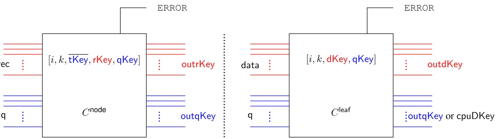
We start by providing an informal description of the data garbling procedure, which turns out to be the most involved part of the construction. The formal description ofGData is provided in Figure4. Our garbled memory consists of two parts.
1. Garbled Circuits: Intuitively our garbled memory will be organized as a binary tree and each node of this tree will correspond to a sequence of garbled circuits. For any garbled circuit itssuccessor is defined as the next garbled circuit in the sequence of garbled circuits corresponding to that node. Similarly we definepredecessoras the previous garbled circuit in the sequence. For a garbled circuit all the garbled circuits in its parent node are referred to as itsparents. Analogously we definechildren. These garbled circuits are obtained by fresh garblings of two separate circuits, one corresponding to the leaf nodes and the other corresponding to non-leaf nodes.
For each of these garbled circuits, we will divide its input wires (and corresponding keys/lables) into two categories, thered input wires and theblue input wires.
Each garbled circuit will containall input keys for its successor. Specifically this includes both the red and the blue input keys of its successor. Additionally each garbled circuit will contain asubsetof input wires for asubsetof its left and right children. Specifically, it will contain the blue input keys for a consecutiveκgarbled circuits among its left children and a consecutiveκgarbled circuits among its right children.
2. Tabled garbled Information:Additionally for each node in the tree as described above, the garbled memory consists of a table of informationTab(i, j), where(i, j)denotes a node in the tree.
ERROR
outrKey
outqKey rec
q Cnode
[i, k,tKey,rKey,qKey]
ERROR
outdKey
outqKeyorcpuDKey
data
q Cleaf
[i, k,dKey,qKey]
Figure 1:Memory circuits.
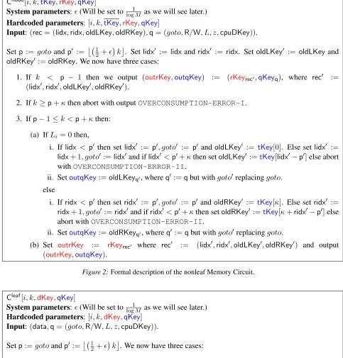
Circuits needed. Next we describe the two circuits, garblings of which will be used to generate the garbled memory. The circuits are described formally in Figures2 and3. The non-leaf node circuit takes as input somerecorded inforecand aqueryq. Garbled labels forrecwill be red and denoted asrKeyand garbled labels forqwill be blue and denoted asqKey. Although every single circuit will have its own uniquerKey
andqKey, when we refer to these in the context of some particular circuit, it will always refer to the keys of its successor and these values will be hard-coded in it. Additionally the circuit has hardcoded inside it its leveliin the tree, its own positionkwithin the sequence of garbled circuits at that node, garbled labels
rKey,qKeyfor its successor, and a collection of labels for the left and right child garbled circuits which we denote astKey. EachtKeyis a vector of exactly2κqKeys, the firstκcorrespond toqKeys for a contiguous block of κ of left child circuits (exactly which ones, we will describe later), and the last κ respectively correspond to labels for circuits in the right child.
The inputs are straightforward,reccontains indices to the first unused left and right child circuits as well as theirqKeys. This allows us to either go left or right, although we will need to update the index and key as soon as we consume it, and we will replace it with something inside oftKey. The queryqis simply a CPU query with one additional “goto” fieldgotothat informs where the first unused circuit in a node should be at to in order to fall inside the window of its parentstKey. If the current circuitk < goto−1, we “burn” the circuit and pass our inputs onto our successor until it is preciselygoto−1, so that the first unused circuit is now indeed located atgoto. In summary, we writeCnode[i, k,tKey,rKey,qKey](rec,q)for non-leaf circuits. Similarly, leaf circuits takes as input somememory datadataand aqueryq. Here, the red key isdKey
which corresponds to the garbled labels of data. A leaf circuit will have hardcoded inside it the current leveli=din the tree, its own positionkwithin the sequence of garbled circuits at that leaf, garbled labels
dKey,qKeyfor its successor. Since a leaf node has no further children, there is no need fortKey. We write
Cnode[i, k,tKey,rKey,qKey]
System parameters:(Will be set tolog1M as we will see later.)
Hardcoded parameters:[i, k,tKey,rKey,qKey]
Input:(rec= (lidx,ridx,oldLKey,oldRKey),q= (goto,R/W, L, z,cpuDKey)).
Setp := gotoandp0 := 1 2 +
k
. Setlidx0 := lidxandridx0 := ridx. Set oldLKey0 := oldLKeyand
oldRKey0:=oldRKey. We now have three cases:
1. If k < p − 1 then we output (outrKey,outqKey) := (rKeyrec0,qKeyq), where rec0 :=
(lidx0,ridx0,oldLKey0,oldRKey0).
2. Ifk≥p+κthen abort with outputOVERCONSUMPTION-ERROR-I.
3. Ifp−1≤k <p+κthen:
(a) IfLi = 0then,
i. Iflidx < p0 then setlidx0 := p0, goto0 := p0 andoldLKey0 := tKey[0]. Else set lidx0 :=
lidx+ 1, goto0:=lidx0and iflidx0 <p0+κthen setoldLKey0 :=tKey[lidx0−p0]else abort
withOVERCONSUMPTION-ERROR-II.
ii. SetoutqKey:=oldLKeyq0, whereq0 :=qbut withgoto0 replacinggoto.
else
i. Ifridx< p0 then setridx0 := p0, goto0 := p0 andoldRKey0 := tKey[κ]. Else setridx0 :=
ridx+ 1, goto0:=ridx0and ifridx0 <p0+κthen setoldRKey0 :=tKey[κ+ridx0−p0]else abort withOVERCONSUMPTION-ERROR-II.
ii. SetoutqKey:=oldRKeyq0, whereq0 :=qbut withgoto0replacinggoto.
(b) Set outrKey := rKeyrec0 where rec0 := (lidx0,ridx0,oldLKey0,oldRKey0) and output
(outrKey,outqKey).
Figure 2:Formal description of the nonleaf Memory Circuit.
Cleaf[i, k,dKey,qKey]
System parameters:(Will be set tolog1M as we will see later.) Hardcoded parameters:[i, k,dKey,qKey]
Input:(data,q= (goto,R/W, L, z,cpuDKey)).
Setp:=gotoandp0 := 12 +k. We now have three cases:
1. Ifk <p−1then we output(outdKey,outqKey) := (dKeydata,qKeyq).
2. Ifk≥p+κthen abort with outputOVERCONSUMPTION-ERROR-I.
3. Ifp−1≤k <p+κthen:
(a) If R/W = read then output (dKeydata,cpuDKeydata), else if R/W = write then output (dKeyz,cpuDKeyz).
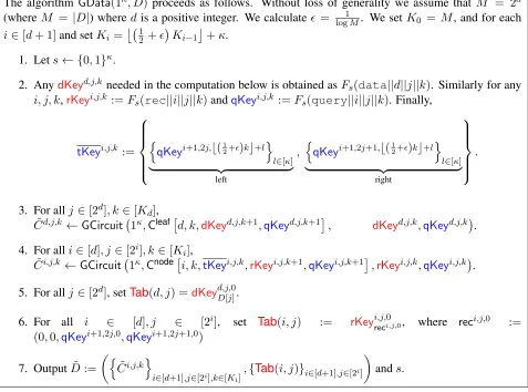
The algorithm GData(1κ, D) proceeds as follows. Without loss of generality we assume that M = 2d (where M = |D|) wheredis a positive integer. We calculate= log1M. We setK0 = M, and for each
i∈[d+ 1]and setKi= 1
2 +
Ki−1+κ.
1. Lets← {0,1}κ.
2. AnydKeyd,j,k needed in the computation below is obtained asFs(data||d||j||k). Similarly for any
i, j, k,rKeyi,j,k :=Fs(rec||i||j||k)andqKeyi,j,k :=Fs(query||i||j||k). Finally,
tKeyi,j,k := n
qKeyi+1,2j,b(12+)kc+l o
l∈[κ]
| {z }
left
,
n
qKeyi+1,2j+1,b(12+)kc+l o
l∈[κ]
| {z }
right .
3. For allj∈[2d], k∈[Kd], ˜
Cd,j,k ←GCircuit 1κ,Cleaf
d, k,dKeyd,j,k+1,qKeyd,j,k+1
, dKeyd,j,k,qKeyd,j,k .
4. For alli∈[d], j ∈[2i], k∈[Ki], ˜
Ci,j,k ←GCircuit 1κ,Cnode
i, k,tKeyi,j,k,rKeyi,j,k+1,qKeyi,j,k+1
,rKeyi,j,k,qKeyi,j,k .
5. For allj∈[2d], setTab(d, j) =dKeyd,j,0 D[j].
6. For all i ∈ [d], j ∈ [2i], set Tab(i, j) := rKeyi,j,0reci,j,0, where reci,j,0 := (0,0,qKeyi+1,2j,0,qKeyi+1,2j+1,0)
7. OutputD˜ :=
n ˜
Ci,j,ko
i∈[d+1],j∈[2i],k∈[K i]
,{Tab(i, j)}i∈[d+1],j∈[2i]
ands.
Figure 4:Formal description ofGData.
Actual data garbing. At a high level, we generate our garbled memory by garbling multiple instances of circuits described in Figures 2 and 3. The formal construction is provided in Figure 4. As men-tioned earlier, these garbled circuits actually correspond to the nodes of a tree. Specifically, if the size of the database is M = 2d, then the root node will contain roughly M κ circuits, each nodes in sub-sequent level will contain roughly half that amount. More specifically, any node at level i contains at most Ki =
j 1 2 +
i
(M +iκ)k + κ garbled circuits. In total, the garbled memory will consist of
Pd
i=0(1 + 2)
i(M +iκ) +κ garbled circuits. Looking ahead will be set to 1
d so that the this num-ber is linear inM+dκ. In order to simplify generation of garbled circuits, we generate all the labels needed for generation of these garbled circuits as the outputs of a PRF on appropriate input values under a fixed seeds. Looking ahead, this will be crucial in extending our construction to allow for generating memory replenishing information. This is elaborated upon in Section8.
4.2 Program Garbling: ( ˜P , sin)←GProg(1κ,1logM,1t, P, s, m)
from memory.
Cstep[t,rootqKey,cpuSKey,cpuDKey]
Hardcoded parameters:[t,rootqKey,cpuSKey,cpuDKey] Input:(state,data).
Compute (state0,R/W, L, z) := CCPUP (state,data). Set q := (goto = t+ 1,R/W, L, z,cpuDKey) and outputrootqKeyqandcpuSKeystate0, unless we are halting in which case only outputstate0in the clear.
Figure 5:Formal description of the step circuit.
TheGProg(1κ,1logM,1t, P, s, m)procedure proceeds as follows.
1. Any cpuSKeyτ needed in the computation below is obtained as Fs(CPUstate||τ), and any
cpuDKeyτ is obtained asFs(CPUdata||τ).
2. Forτ =m, . . . , m+t−1do:
(a) SetqKey0,0,τ :=Fs(query||0||0||τ).
(b) C˜τ ←GCircuit 1κ, Cstepτ,qKey0,0,τ,cpuSKeyτ+1,cpuDKeyτ+1,cpuSKeyτ,cpuDKeyτ
3. OutputP˜ :=m,{C˜τ}τ∈{m,...,m+t−1},cpuDKeym0 ,sin =cpuSKeym
Figure 6:Formal description ofGProg.
4.3 Input Garbling: x˜←GInput(1κ, x, sin)
Informally, theGInputalgorithm usesxas selection bits for the labels provided bysinand outputsx˜, which is just the selected labels. A formal description ofGProgis provided in Figure7.
The algorithmGInput(1κ, x, sin)proceeds as follows.
1. ParsesinascpuSKeyand outputx˜:=cpuSKeyx.
Figure 7:Formal description ofGInput.
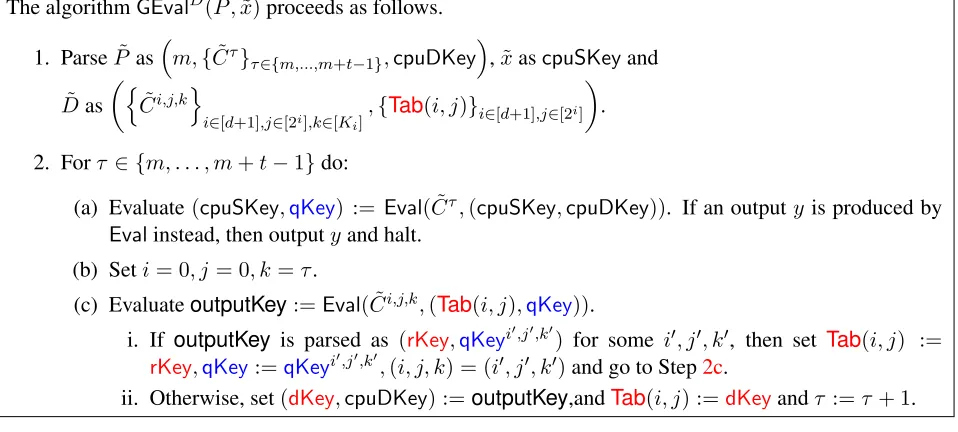
4.4 Garbled Evaluation: y←GEvalD˜( ˜P ,x˜)
The GEval procedure gets as input the garbled program P˜ = m,{C˜τ}τ∈{m,...,m+t−1},cpuDKey, the
garbled inputx˜=cpuSKeyand random access into the garbled databaseD˜ = ({C˜i,j,k}
The algorithmGEvalD˜( ˜P ,x˜)proceeds as follows.
1. ParseP˜asm,{C˜τ}τ∈{m,...,m+t−1},cpuDKey,x˜ascpuSKeyand
˜
Das
n ˜
Ci,j,k
o
i∈[d+1],j∈[2i],k∈[K i]
,{Tab(i, j)}i∈[d+1],j∈[2i]
.
2. Forτ ∈ {m, . . . , m+t−1}do:
(a) Evaluate(cpuSKey,qKey) := Eval( ˜Cτ,(cpuSKey,cpuDKey)). If an outputy is produced by
Evalinstead, then outputyand halt.
(b) Seti= 0, j= 0, k=τ.
(c) EvaluateoutputKey:=Eval( ˜Ci,j,k,(Tab(i, j),qKey)).
i. If outputKey is parsed as (rKey,qKeyi0,j0,k0) for some i0, j0, k0, then set Tab(i, j) :=
rKey,qKey:=qKeyi0,j0,k0,(i, j, k) = (i0, j0, k0)and go to Step2c.
ii. Otherwise, set(dKey,cpuDKey) :=outputKey,andTab(i, j) :=dKeyandτ :=τ + 1.
Figure 8:Formal description ofGEval.
5
Cost and Correctness Analysis
5.1 Overall Cost
Before we analyze the cost of the main algorithms, we first calculate the sizes of all the constituent variables and circuits. The database Dhas size|D| = M elements, and each data element is of|data| = B bits. Garbled labels for each bit of an input wire areλbits long. The complete garbled labels forninput bits takes up2λnbits. Furthermore, the current time stepmorτ we upper bound by the total combined running timeT. Of course,B, λ, T are allpoly(κ), and for the two former values we simply absorb them into the
poly(κ)term, whereas we keepT as a separate parameter for later use.
From this, we can compute|cpuSKey|= 2λ|state|and|cpuDKey|= 2λB. A queryqhas size|goto|+ |R/W|+|L|+|z|+|cpuDKey| ≤logT+ 1 + logM+B+ 2λB, and|qKey|= 2λ|q|. SincedKeyare just the labels for memory data,|dKey|= 2λB. Next, we compute the size ofrec. Observe thatoldLKeyand
oldRKeyare simplyqKeys, so we have|rec|=|lidx|+|ridx|+|oldLKey|+|oldRKey| ≤2(logT+|qKey|). Finally,tKeyconsist of2κqKeys and therefore have size|tKey|= 2κ|qKey|.
Now we calcluate |Cnode|. Observe that the calculations within the circuit are primarily comparisons, and overall is at most polynomial in the size of the input and hardwired values. Thus|Cnode|=poly(|i|+ |k|+|tKey|+|rKey|+|qKey|+|rec|+|q|) =poly(logM,logT, κ)and so is its garbled version.
Next, we calcluate|Cleaf|. We have|Cleaf[i, k,dKey,qKey](data,q)|=poly(|i|+|k|+|dKey|+|qKey|+ |data|+|q|) =poly(logM,logT, κ)and so is its garbled version.
Finally, we calcluate|Cstep|. We assume that the plain CPU has sizepoly(logM,logT, κ). Since the step circuit simply computes theCP U circuit and does a few selections, we have: |Cstep|=poly(logT+ |qKey|+|cpuSKey|+|cpuDKey|+|state|+|data|+|CP U|) =poly(logM,logT, κ).
We can now calculate the cost of the individual algorithms.
5.1.1 Cost ofGData
c=e2and let= log1M.
First, we show how to bound bound Ki ≤ 12 + i
M +Pi−1 j=0
1 2+
j
κ. This can be shown by induction: K0 = M, and by induction, Ki+1 =
1 2 +
Ki
+κ ≤ 1 2 +
Ki +κ ≤ 12+ · h 1 2 + i
M+Pi−1 j=0 12 +
j
κi+κ≤ 12 +i+1
M +Pi+1−1 j=0 12 +
j
κ.
This bound can then be simplified toKi ≤ 12+ i
(M+iκ). Thus, overall, we calculate the number of garblings ofCnodeas
d−1 X
i=0
2i·Ki≤ d−1 X
i=0 2i·
1 2+
i
(M+iκ)
≤ d−1 X
i=0
(1 + 2)i(M+dκ)
≤ (1 + 2) d−
1
(1 + 2)−1(M+dκ)
≤ e 2d−1
2 (M+dκ)
Since = 1/d, and garbling such circuits takes poly(logM,logT, κ) time, this overall takes M ·
poly(logM,logT, κ)time and space. At the leaf level, it performs at most 2d·(12 +)d(M +dκ) gar-blings ofCleaf. Again, this takespoly(logM,logT, κ)·M time and space. Finally, there areO(M)ofrKey
anddKeyvalues stored inTab(i, j), which is againpoly(logM,logT, κ)·M. 5.1.2 Cost ofGProg
The algorithm GProg(1κ,1logM,1t, P, s, m) computes t cpuSKeys,cpuDKeys, and qKeys. It also gar-bles t Cstep circuits and outputs them, along with a singlecpuSKey. Since each individual operation is
poly(logM,logT, κ), the overall time and space cost ispoly(logM,logT, κ)·t.
5.1.3 Cost ofGInput
The algorithmGInput(1κ, x, sin)selects labels of the state key based on the state as input. As such, the time and space cost is|cpuSKey|.
5.1.4 Cost ofGEval
We first assume that an error does not occur inGEval. As we shall see in Section5.2that this occurs with all but negligible probability. We analyze how many circuits were consumed afterT steps in order to obtain the amortized cost ofGEval. We letkidenote the maximum number of circuits consumed in some node at leveli. At the root, exactlyT circuits were consumed sok0 =T, and in order for levelito not overflow, it must not have consumed more than 12 +
ki−1+κ circuits. By the same analysis of the bound of
Ki, it must be the case that ki ≤ 12 + i
(T +iκ). Then no more than Pd
as the bound on the number of nodes ever touched per level suffices:
d X
i=0
min(2i, T)ki≤ d X
i=0
min(2i, T)
1 2 +
i
(T +iκ)
≤T
d X
i=0
min(2i, T)
1 2 +
i
+min(2 i, T)iκ
T
!
≤T
d X
i=0 (2i)(
1 2+
i
) +(T)iκ
T
!
≤T
d((1 + 2)d+dκ)
≤T d(e2+dκ).
When accounting for the cost of each of these circuits being evaluated, this means that the amortized cost isT ·poly(logM,logT, κ)overall.
5.2 Correctness
Observe that as long as the memory data is correctly stored and passed on to the CPU step circuits, the scheme is correct. The only way this can fail to happen is if a query q fails to make it from the root to the leaf. In order to demonstrate this, we need to analyze two things. We must show that a parent ciruit will always output the properqKeyfor the first unused child circuit, and we also must show that the errorsOVERCONSUMPTION-ERROR-IandOVERCONSUMPTION-ERROR-IIdo not occur except with a negligible probability.
Lemma 5.1. WithinCnode,lidxalways points to the first unused left child circuit which hasqKeyequal to
oldLKey, andridxalways opint to the first unused right child circuit which hasqKeyequal tooldRKey.
Proof. WLOG we show this for the left child. We prove this by induction on the current CPU step. In the base case, this is true due to the way GDataset up the keys. Now suppose we are consuming some parent circuit and it was true for the previous circuit, i.e.lidxandoldLKeycorrectly point to the first unused left child circuit. Then it remains to show thatlidx0points to what will be the first unused left child circuit during the next CPU step, and that the updated old keyoldLKey0 points to it. Recallp0 =b(12 +)kc, and by definition ofGData, this is precisely the child circuit thattKey[0]is theqKeyof. Iflidx <p0 then the child circuit will burn until thegoto0circuit, which is exactly whatlidx0 is set to be, andoldLKey0 is set to
tKey[0]which is precisely whatlidx0 =goto0is set to. On the other hand, iflidx> goto0 then by definition,
goto0 = lidx0 =lidx+ 1andoldLKey0 holds the key for precisely the next circuit past lidx. But we know that the child node will consume exactly one circuit sincegoto0is precisely one pastlidxwhich by induction is the current child index, solidx0will point to the first unused child circuit andoldLKey0is its key.
Lemma 5.2. The errorsOVERCONSUMPTION-ERROR-IandOVERCONSUMPTION-ERROR-IIdo not occur except with a negligible probability.
Proof. Again, WLOG we show this for the left child. Note that an error can never occur at the root, and
OVERCONSUMPTION-ERROR-Iwould occur if and only if anOVERCONSUMPTION-ERROR-IIwould
synchronizeevent, which is namely that the parent is on circuitkand the child is on circuitb(12 +)kc, or more precisely, whengoto0 =b(1
2 +)kc. We letm0 < m1be the latest point for the parent for which this synchronize occured. We know that such anm0exists, since timem0 = 0is a valid solution.
Because there have been no more burns since that time, each time the left child was visited, exactly one circuit was also consumed. Atm0, exactlyb(12+)m0cchild circuits were consumed, and atm1, more than b(12 +)m1c+κchild circuits would have been consumed (if we did not break on error). During this time,
m1−m0parent circuits were consumed, so the parent node was visited at mostm1−m0times (it could be less due to burning), and we expect the child node to be visitedµ= m1−m02 times. Fort= 0, . . . , m1−m0, letXtdenote the 0/1 random variable indicating that on time stepm0+tthe left node was visited, and let
X =Pm1−m0
t=0 Xt. We calculate the probability thatP r[X >b( 1
2 +)m1c+κ− b( 1
2 +)m0c]which is the probability that this error would have occurred. This becomesP r[X > 12+
(m1−m0)
+κ−1]. Note that we can trivially condition on the case where m1 −m0 > κ, because otherwise X < κ with probability 1, so we can concludeµ > κ/2.
Substitutingδ = 2+κ−1µ , this becomesP r[X > (1 +δ)µ]. Then by the Chernoff bound forδ > 0,
P r[X >(1 +δ)µ]≤exp((δ−(1 +δ) ln(1 +δ))µ).
Then reorganizing terms and using a second-order log approximation:
P r[X >(1 +δ)µ]≤exp
δ+ (1 +δ) log
1− δ 1 +δ
µ
≤exp
δ+ (1 +δ)
− δ 1 +δ −
δ2
(1 +δ)2 µ ≤exp − δ 2µ
1 +δ
≤exp −δµ δ
1 +δ
≤exp
−(2µ+κ−1)
2+ (κ−1)/µ
1 + 2+ (κ−1)/µ
≤exp
−(2µ+κ−1)
2
1 + 2
≤exp
−(2µ+κ−1)
2
1 + 1
≤exp
−(22µ+(κ−1))
Since= log1M, this is negligible.
6
Secure Main Construction
We state the theorem that we attempt to prove and show where there is a barrier and how we work around it by modifying our solution.
We first provide the intuition of how we would like the proof would go through. Our goal is to construct a simulator Simsuch that only given the access pattern and output (and not the database contents) it can simulate the view of the evaluator. The first observation is that the only point of the PRFF was to allow
simply remember all these values internally, and therefore the first step is to replaceF with a truly random table thatSimkeeps track of.
Next, we must simulate the garbled circuits one at a time. In order to do so, we order the circuits by the order in which they were evaluated, and then define a series of hybrids where hybrid ihas the firsti
garbled circuits simulated. The hybrids are constructed so that the circuits are simulated in reverse order, such that thei-th circuit is simulated first, and so on, until the first circuitC˜0is simulated. At first glance, this appears to work, but there is actually a subtle issue. EachqKeyof a circuit in a node circuit resides in several locations: the predecessor circuit in the same node, and inside severaltKey,oldLKey,oldRKeyof circuits in its parent node. Indeed, if a fullqKeyappears anywhere (whether as a passed or hardwired value) in the current hybrid, then this causes a “circularity” issue. In order to overcome this barrier, wepasstKey
from circuit to circuit instead of hardwiring them as seen in Figures9and10.
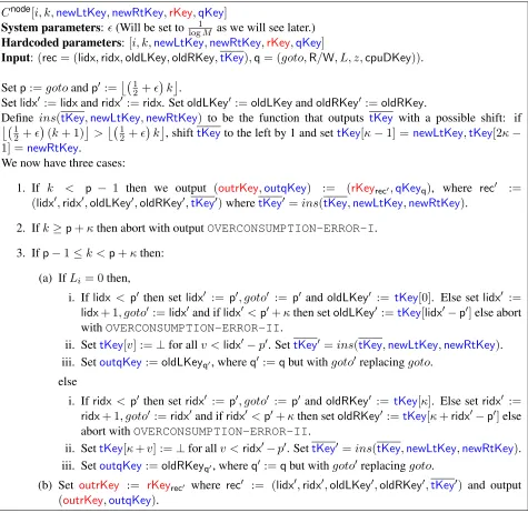
Cnode[i, k,newLtKey,newRtKey,rKey,qKey]
System parameters:(Will be set tolog1M as we will see later.) Hardcoded parameters:[i, k,newLtKey,newRtKey,rKey,qKey]
Input:(rec= (lidx,ridx,oldLKey,oldRKey,tKey),q= (goto,R/W, L, z,cpuDKey)).
Setp:=gotoandp0 := 1 2 +
k .
Setlidx0 :=lidxandridx0:=ridx. SetoldLKey0:=oldLKeyandoldRKey0 :=oldRKey.
Define ins(tKey,newLtKey,newRtKey) to be the function that outputs tKey with a possible shift: if 1
2 +
(k+ 1)
> 1 2 +
k
, shifttKeyto the left by 1 and settKey[κ−1] =newLtKey,tKey[2κ−
1] =newRtKey.
We now have three cases:
1. If k < p − 1 then we output (outrKey,outqKey) := (rKeyrec0,qKeyq), where rec0 :=
(lidx0,ridx0,oldLKey0,oldRKey0,tKey0)wheretKey0 =ins(tKey,newLtKey,newRtKey).
2. Ifk≥p+κthen abort with outputOVERCONSUMPTION-ERROR-I.
3. Ifp−1≤k <p+κthen:
(a) IfLi = 0then,
i. Iflidx < p0 then setlidx0 := p0, goto0 := p0 andoldLKey0 := tKey[0]. Else set lidx0 :=
lidx+ 1, goto0:=lidx0and iflidx0 <p0+κthen setoldLKey0 :=tKey[lidx0−p0]else abort
withOVERCONSUMPTION-ERROR-II.
ii. SettKey[v] :=⊥for allv <lidx0−p0. SettKey0=ins(tKey,newLtKey,newRtKey). iii. SetoutqKey:=oldLKeyq0, whereq0 :=qbut withgoto0 replacinggoto.
else
i. Ifridx< p0 then setridx0 := p0, goto0 := p0 andoldRKey0 := tKey[κ]. Else setridx0 :=
ridx+ 1, goto0:=ridx0and ifridx0 <p0+κthen setoldRKey0 :=tKey[κ+ridx0−p0]else abort withOVERCONSUMPTION-ERROR-II.
ii. SettKey[κ+v] :=⊥for allv <ridx0−p0. SettKey0 =ins(tKey,newLtKey,newRtKey). iii. SetoutqKey:=oldRKeyq0, whereq0 :=qbut withgoto0replacinggoto.
(b) Set outrKey := rKeyrec0 where rec0 := (lidx0,ridx0,oldLKey0,oldRKey0,tKey0) and output
(outrKey,outqKey).
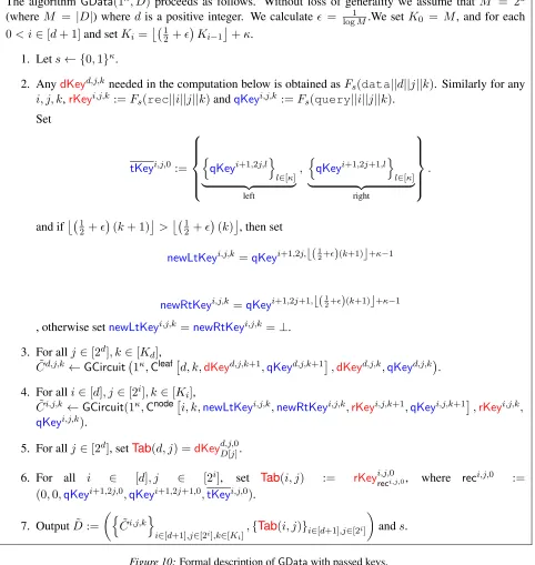
The algorithm GData(1κ, D) proceeds as follows. Without loss of generality we assume that M = 2d (where M = |D|) wheredis a positive integer. We calculate = log1M.We setK0 = M, and for each 0< i∈[d+ 1]and setKi=
1 2 +
Ki−1+κ.
1. Lets← {0,1}κ.
2. AnydKeyd,j,k needed in the computation below is obtained asFs(data||d||j||k). Similarly for any
i, j, k,rKeyi,j,k :=Fs(rec||i||j||k)andqKeyi,j,k :=Fs(query||i||j||k).
Set
tKeyi,j,0 := n qKeyi+1,2j,l o l∈[κ]
| {z }
left , n qKeyi+1,2j+1,l o l∈[κ]
| {z }
right .
and if 1 2 +
(k+ 1)
> 1 2 +
(k)
, then set
newLtKeyi,j,k =qKeyi+1,2j,b(12+)(k+1)c+κ−1
newRtKeyi,j,k =qKeyi+1,2j+1,b(12+)(k+1)c+κ−1
, otherwise setnewLtKeyi,j,k =newRtKeyi,j,k =⊥.
3. For allj∈[2d], k∈[K d], ˜
Cd,j,k ←GCircuit 1κ,Cleafd, k,dKeyd,j,k+1,qKeyd,j,k+1,dKeyd,j,k,qKeyd,j,k.
4. For alli∈[d], j ∈[2i], k∈[Ki], ˜
Ci,j,k ←GCircuit(1κ,Cnodei, k,newLtKeyi,j,k,newRtKeyi,j,k,rKeyi,j,k+1,qKeyi,j,k+1,rKeyi,j,k,
qKeyi,j,k).
5. For allj∈[2d], setTab(d, j) =dKeyd,j,0D[j].
6. For all i ∈ [d], j ∈ [2i], set Tab(i, j) := rKeyi,j,0reci,j,0, where reci,j,0 := (0,0,qKeyi+1,2j,0,qKeyi+1,2j+1,0,tKeyi,j,0).
7. OutputD˜ :=
n ˜
Ci,j,k
o
i∈[d+1],j∈[2i],k∈[K i]
,{Tab(i, j)}i∈[d+1],j∈[2i]
ands.
Figure 10:Formal description ofGDatawith passed keys.
dropped) nor asymptotic cost. We argue correctness as follows: within a node, the sequence ofoldLKeyand
oldRKeywithin the circuits is an increasing sequence, and oldLKeystrictly increases if we are going left, andoldRKeystrictly increases if we are going right. Note that thetKey shifting corresponds precisely to the previous windows with the only difference being now there could be some keys set to⊥. Thus, the only way this scheme could be incorrect is if we attempt to assign a ⊥tooldLKeyoroldRKey. But all the⊥ values correspond to indexes that are strictly less than the currentoldLKeyoroldRKeyindex, and therefore cannot be the new index.
We demonstrate a series of lemmas that ensures that when some circuit needs to be simulated, all ap-pearances of its keys will have been in already been simulated or dropped. This strategy then allows the full simulation proof goes through as we will see in Section7.
7
Security Proof
In this section we prove the UMA2-security of the black-box garbled RAM(GData,GProg,GInput,GEval).
Theorem 7.1(UMA2-security). LetFbe a PRF and(GCircuit,Eval,CircSim)be a circuit garbling scheme, both of which can be built from any one-way function in black-box manner. Then our construction is a UMA2-secure garbled RAM scheme for uniform access programs running in total timeT < Mmaking only black-box access to the underlying OWF.
Proof. We first prove a lemma (Lemma7.3) before proving our main theorem. For the lemma, we consider ourselves during the course of GEval, where we are about to evaluate some non-root node C˜i,j,k. Our eventual goal is to show that all instances ofqKeyi,j,k are in previously evaluated (hence, will be simulated) circuits, and is not being passed as part of anytKey.
Fact 7.2. TherKeyrecto be consumed byC˜i,j,kwas output byC˜i,j,k−1, or initially stored inTab(i, j)in the case wherek = 0. TheqKeyq used to evaluateC˜i,j,k was either output by (Case 1)C˜i,j,k−1 or (Case 2)
˜
Ci−1,bj/2c,k0 for somek0.
To further pinpoint whereqKeys are stored, we group the circuits in the parent node into three groups. We letkmin0 be the smallest value such thatb(1
2 +)k 0
minc+κ−1 =k, andkmax0 be the largest value such thatb(1
2 +)k 0
maxc = k. For a parent circuitC˜i−1,bj/2c,k
0
, we call it apast circuit ifk0 < kmin0 , afuture circuit ifk0 > k0max, and apresentcircuit ifkmin0 ≤k0 ≤k0max.
We now state our main lemma.
Lemma 7.3. Suppose during the execution of GEval, we are about to evaluate garbled circuitC˜i,j,k. Let
qKeydenoteqKeyi,j,k. Then all instances ofqKeyexist only in previously evaluated circuits.
Proof. We letk? denote the index of the last parent circuit that evaluated prior to our current circuit, i.e. ˜
C? = ˜Ci−1,bj/2c,k?was the last circuit to be evalauted at leveli−1. WLOG assume that the current circuit is the left child of the parent. Observe thatqKeyonly occurs in the following locations: the predecessor circuit, insidenewLtKeyof the final “past” parent, or inside some “current” or “future” parent’soldLKeyor
tKey. Since the predecessor circuit must be evaluated already, we only need to check the existence ofqKey
inside one or more of my parent circuits.
Letlidxbe the left index (implicitly) passed intoC˜?, and letlidx0be the left index (implicitly) output by it.
Observe that by definition,qKeyis not in thetKeyof any past or future parent. In particular, it can only be included insidetKeywhen being inserted as anewLtKey, and once it is removed it can never be present again in any future parent’stKey. Note thatqKeymay still be insidenewLtKeyof a past parent oroldLKey
only need to argue that no (unevaluated) parent circuitk0 > k?containsqKeyas eithertKey,newLtKey,or
oldLKey.
We analyse the following six cases:
[Case 1A] The predecessor circuitC˜i,j,k−1output myqKeyq, andk?belongs to a past parent.
[Case 1B] The predecessor circuitC˜i,j,k−1output myqKeyq, andk?belongs to a present parent.
[Case 1C] The predecessor circuitC˜i,j,k−1output myqKeyq, andk?belongs to a future parent.
[Case 2A] The parent circuitC˜i−1,bj/2c,k?output myqKeyq, andk?belongs to a past parent.
[Case 2B] The parent circuitC˜i−1,bj/2c,k?output myqKeyq, andk?belongs to a present parent.
[Case 2C] The parent circuitC˜i−1,bj/2c,k?output myqKeyq, andk?belongs to a future parent.
CASE 1A. This case cannot occur. SinceC˜? was a past parent, by definition we must haveb(1 2 +)k
?c+
κ−1 < k. Since qKey was passed from the predecessor circuit, it must have taken the branch where
k−1 < goto0 −1 = b(1 2 +)k
?c − 1. Combining these two inequalities yields κ < 2 which is a
contradiction.
CASE1B,1C. Note thatk−1< goto0−1still holds. We know thatlidx0 ≥goto0, so we have thatlidx0 > k.
SinceoldLKey0 is the key for circuitlidx0, it cannot be theqKeyfork. Furthermore, all keys insidetKey
with index less than lidx0 have been set to⊥byC˜? so no unevaluated parent circuit can have the current
qKeyas part of tKeyoroldLKey. Finally, qKeyappearing as newLtKeycan only occur in a past parent, which has already been evaluated in this case.
CASE 2A. This case cannot occur. By the definition ofCnode, the only way the parent circuit could output my qKeyq directly is if it is held as oldLKey. However, the oldLKey is only assigned due to the value contained in an oldertKeyin some parent circuitk0≤k?. The indiceskof any parentk0≤k?parents is at mostb(1
2 +)k
0c+κ−1≤ b(1 2 +)k
?c+κ−1 < kby definition ofk? being a past parent. Therefore,
qKeycould not have been output by any past parent circuit.
CASE 2B. In this case, k? belongs to a present circuit that was evaluated. Note that C˜? replaced its
oldLKey = qKey with some new oldLKey0 which corresponds to the lidx0-th circuit at level i. Since
k = lidx < lidx0 and all tKey[v] is set to ⊥ for v < lidx0 −p0, the current qKey was removed from
tKeybyC˜? and hence all successor parent circuits’tKeydo not containqKey. Furthermore,oldLKeycan only be updated bytKeyandC˜? does not set the updatedoldLKey0 toqKey, and no parent circuitk0 > k?
can setoldLKeytoqKeysince it is no longer contained in any of theirtKeyvalues. Finally,qKeyappearing
asnewLtKeycan only occur in a past parent, which has already been evaluated in this case.
CASE 2C. Because k? belongs to a future parent that was evaluated, it must be the case that all past
and present parents have already been evaluated. We check that qKeydoes not exist in any unevaluated parent circuit’stKeyoroldLKey: all parent circuitsk0 ≤k? have been evaluated,C˜? was evaluated and it output and replaced theqKeysitting inoldLKeywith sometKey. SinceC˜?and all its successors are future parents, none of them haveqKeyinside itstKeyand thusoldLKeywould never containqKey. Finally,qKey
appearing asnewLtKeycan only occur in a past parent, which has already been evaluated in this case.
We now proceed to prove the theorem. LetCircSimbe the garbled circuit simulator. Suppose in the real execution, a total ofwcircuits are evaluated byGEval. We constructSimand then give a series of hybrids
ˆ