ISSN (Print) : 2320 – 3765 ISSN (Online): 2278 – 8875
I
nternational
J
ournal of
A
dvanced
R
esearch in
E
lectrical,
E
lectronics and
I
nstrumentation
E
ngineering
(An ISO 3297: 2007 Certified Organization)
Vol. 5, Issue 11, November 2016
PID Controller Design for a Flexible Aircraft
Swaroop S1, Dr. H Prasanna Kumar2
PG Student, Department of Electrical Engineering, University Visvesvaraya College of Engineering,
Bengaluru, Karnataka, India1
Assistant Professor, Department of Electrical Engineering, University Visvesvaraya College of Engineering,
Bengaluru, Karnataka, India2
ABSTRACT: This paper presents a comparative assessment based on time response specification performance between modern and intelligent controller for a pitch control system of an aircraft system. The dynamic modelling of pitch control system is considered on the design an autopilot that controls the pitch angle of an aircraft. It begins with a derivation of suitable mathematical model to describe the dynamics of an aircraft. To study the effectiveness of the controllers, the PID controller is developed for controlling the pitch angle of an aircraft system. Simulation results for the response of pitch controller are presented in time domain. Finally, the performances of pitch control systems are investigated and analysed based on time response in order to identify which control strategy delivers better performance with respect to the desired pitch angle.
KEYWORDS: pitch control, PID controller, and dynamic model.
I. INTRODUCTION
The large transport aircraft will exhibit a higher flexibility due to a global decrease of modal frequencies, which results in a stronger interaction between the flight control system and the aircrafts structural modes[1]. Thus, a flight control law design based only on the rigid modes is no more sufficient to meet the performances requirements of a flexible aircraft. Ensuring appropriate stability margins and providing satisfactory ride quality for passengers needs to actively control the aero elastic modes[2, 3]. As a result, the means of obtaining the simplest accurate mathematical models of a flexible aircraft is a most important problem in aircraft dynamics to support control laws synthesis[4]. These models must represent with high fidelity the relationships between the surface control deflections and the output signals used by the controller, at both low and high frequency. To achieve this, initially we need to develop a flexible aircraft model and further required to reduce this higher order mathematical model appropriately depends on the application. The reduction of simplified model can be done in such a manner that the dominant modes are retained in the model. This will ensure the simplest model to make use of effective dynamic analysis and control synthesis, and also benefited to ease the computation burden.
ISSN (Print) : 2320 – 3765 ISSN (Online): 2278 – 8875
I
nternational
J
ournal of
A
dvanced
R
esearch in
E
lectrical,
E
lectronics and
I
nstrumentation
E
ngineering
(An ISO 3297: 2007 Certified Organization)
Vol. 5, Issue 11, November 2016
II. FLEXIBLE AIRCRAFT MODEL
The pitching motion of a flexible aircraft can be described by the following linear form[7, 8]. e
x
Ax
B
(1)Where
x
is a state vectors, which consists of
, ,
q
1,
2,
3,
4, 1, 2,3,4,
is the angle of attack,q
is thepitch rate,
e is the elevator input,
1,
2,
3,
4
are the elastic states and
1 2 3 4
(.), (.), (.), (.), (.), (.)
Z m
C C C C C C are
the non-dimensional derivatives. The structural flexibility effects of aircraft are included in the stability matrix
A
andcontrol matrix
B
. They are partitioned in the following form12 21 22 1 1 2 1 Aeroelastic Rigid Body
terms coupling Term s (A )
,
R igidBody Structural
couplingTerms (A ) flexibilty T erms (A ) Rigid Body
control Derivatives (B ) Structural M ode
control Derivatives (B
( ) ) A A B (2)
1 0 2 0 2 0 2 0 2 0 0 0 0
0 0 2 1 2 3 4 1 2 3 4
1 1 2 1 2 1 2 1 2 1 2 1 1 1 1
1 2 3 4
1 2 3 4
11
;
12
L L C L L C L L C L L C L C L C L C L C
C L L L C Z Z Z Z Z Z Z Z
z Zq
L C L L C L L C L L C L L C L L C L C L C L C L C
m mq m m m m m m m m
A
A
21
3
1 2 4
3 5 7 9
3
1 2 4
3 2 5 2 7 2 9 2
0 0 0 0
0 0 0 0
T
L C L C L C L C
L L Cq L L Cq L L Cq L L Cq
A 1 2
0
3
1 2 4
5 7
3 9
1
; 0 0 0 0
T L Cz e
L C L C L C L C
e e e e
L Cm e
B B
22
2
1 2 1 1 1 1 1 1 1
4 1 1 1 4 2 4 3 4 4 3 1 1 3 2 3 3 3 4
2
2 2 2 2 2 2 2 2 2
5 5 5 5
6 1 6 2 2 2 6 3 6 4 1 2 2 3 4
3 3 3 2 3 3 3
7 7 7
8 8 8 3 3 8 1 2
1 2 3 4
L C L C L C L C L C L C L C L C
L C L C L C L C L C L C L C L C
L C L C L C L C L C L C L C
A
2
0 1 2
2 2 3 4 1 1 2 3 3 7 3 3 4 2
4 4 4 4 2 4 4 4 4
9 1 10 2 10 3 10 4 4 4 9 1 9 2 9 3 9 3 4
, , , ,
1 0 0 0 0 0 0 0
0 1 0 0 0 0 0 0
0 0 1 0 0 0 0 0
0 0 0 1 0 0 0 0
2 2 2
2 4 y L C
L C L C L C L C L C L C L C L C
uS u Sc c
L L L
m I u
u Sc uSc
L L
m m
2 5
2
2 2 2 2
6 7 8 9
2 3 3 4
, ,
, , ,
2
4 2 4 2
u Sc L m uSc u Sc uSc u Sc
L L L L
m m m m
Aircraft mass m, wing area S, wing chord c, air density , total inertial velocity u, the moment inertia about Y-axis
I
y, and the other quantities are used for describing the sub matrices of A and B. Rigid body portions of the aircraft model are given by the rigid body terms and its control derivatives. The structural mode of aircraft model is described by the Structural flexibility terms and structural control derivatives. The control derivatives of structural modes are allowed the control deflections to drive the structural modes. Aeroelastic coupling and rigid body coupling terms provide the coupling between the rigid-body and the structural flexibility of the aircraft. The structural modes of flexible aircraft are excited by the influence of rigid body coupling terms on rigid-body response of the aircraft. The rigid-body response of the aircraft is influenced by the structural modes in terms of Aeroelastic coupling terms.
ISSN (Print) : 2320 – 3765 ISSN (Online): 2278 – 8875
I
nternational
J
ournal of
A
dvanced
R
esearch in
E
lectrical,
E
lectronics and
I
nstrumentation
E
ngineering
(An ISO 3297: 2007 Certified Organization)
Vol. 5, Issue 11, November 2016
many control design techniques. Moreover, controllers designed based on linear system whose dynamic order greater than or equal to the design model. If the prominent physical aspects of the nonlinear system dynamics can be retained in the lower order linear model, the effective controllers are allowed to design from linear system with significantly simple structure. Since reduced order model approximates some aspects of the full order system dynamics, model simplification process starts from the linearization of the system dynamics about an equilibrium condition[10].
Table 1: Geometry, Inertia and Flight Condition of flexible aircraft
The linear flexible model is simulated for controlling in the desired trajectory. It can be observed that the dynamics are in stable condition or trim condition i.e. when there is no input , the variable remain constant or even after the excitation of the control input, the states of the variables return to the original condition. Hence the system is stable. The simulated aircraft contains four aeroelastic frequency and it is shown in frequency response plot. Since the model become complex after adding the structural modes, the mathematical model is reduced to lower order in order to help in designing effective control system. The various methods like Balanced Realization, Truncation, Residualization, Moment Matching, Pade’s approximation are used in our study. The reduced order model resemble the same dynamics of the original model. In the process of reduction the full order nonlinear model is linearized at equilibrium condition then the available model order reduction methods are applied to it.
Since the linear control system is well developed various methods for designing effective control system are available in literature. In that the poplar one is the PID controller design. In the simulation study the elevator input contains 3211 input which has all range of frequencies. In the pitch controller design, the desired tracking command is given as the reference input. The PID controller tuning is done on the Z-N tuning method. The response of the PID controller is recorded and found to be effective. Basically the controller is designed based upon the reduced order model but it is applied on the original model hence the model reduction should be done accurately. For any controller to perform better the effective feedback to the controller is very important in this regard the negative feedback is given to the input of the controller.
Geometry
c
= 4.664 m (mean chord)b
= 21.336 m (wing span)S
= 180.79 m2 (platform area)
= 65 deg (sweep angle)Weight
W
= 130,642.3 Kg (net weight)Inertia
xx
I
= 1,288,066 Kg-m2I
yy= 8,677,503 Kg-m2zz
I
= 9,626,605 Kg-m2I
xz= -71,453 Kg-m2xy
I
=I
yz= 0Frequency of Structural modes
1
6.29,
2
7.04,
3
10.59,
4
11.03
Modal damping
1
2
3
4
0.02
Modal generalized mass
M
1
248.94Kg-m2
,
M
2
12998.0kg-m23
ISSN (Print) : 2320 – 3765 ISSN (Online): 2278 – 8875
I
nternational
J
ournal of
A
dvanced
R
esearch in
E
lectrical,
E
lectronics and
I
nstrumentation
E
ngineering
(An ISO 3297: 2007 Certified Organization)
Vol. 5, Issue 11, November 2016
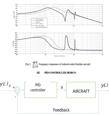
Fig 1:
( )
( )
eq s
s
Frequency responses of reduced order flexible aircraft.III. PID CONTROLLER DESIGN
Fig 2: PID controller design block diagram
The desired pitch tracking controller is designed using the Ziegler–Nichols PID tuning method.The tuning values are
given by kp=0.1907, ki=0.233, kd=0.0575. Tracking response of the PID controller for tracking the desired pitch angle is given in figure 3. It can be observed that the pitch tracking response of the flexible aircraft performing in effective manner. The over shoot in comparatively low and oscillations are due to the elastic nature of the structure. The strong PID controller stabilises the over shoot and oscillations in a very short period and controller tracks the command in the required manner.
d
y
AIRCRAFT
y
u
+
-Feedback
ISSN (Print) : 2320 – 3765 ISSN (Online): 2278 – 8875
I
nternational
J
ournal of
A
dvanced
R
esearch in
E
lectrical,
E
lectronics and
I
nstrumentation
E
ngineering
(An ISO 3297: 2007 Certified Organization)
Vol. 5, Issue 11, November 2016
IV. CONCLUSION
This paper introduces the modelling and performance analysis of a linear flexible aircraft, controller is designed using the PID controller. Then using MATLAB coding, the flexible aircraft is implemented and designed control system is simulated for verifying its performance. The simulation shows the designed controller is effective and feasible.
Fig 3: PID controller response for the given pitch angle tracking input.
REFERENCES
[1] R. D. Milne, "Dynamics of the deformable aeroplane," Aeronautical Research Council, Technical Report ARC R.&M. 3345,1962. [2] A.R. Dusto, G.W. Brune, G.M. Dornfeld, J.E. Mercer, S.C. Pilet, P.E. Rubbert, et al., "A method for predicting the stability characteristics
of an elastic airplane," National Aeronautics and Space Administration, Technical Report NASA-CR-114712,1974. [3] I. Tuzcu, "On the stability of flexible aircraft," Aerospace Science and Technology, vol. 12(5), pp. 376–384, 2007.
[4] D. K. Schmidt and D. L. Raney, "Modeling and simulation of flexible flight vehicles," Journal of Guidance, Control, and Dynamics, pp. 539–546, May-Jun 2001.
[5] M. R. Waszak and D. K. Schmidt, "Flight dynamics of aeroelastic vehicles," Journal of Aircraft, pp. 563–571, June 1988.
[6] M. R. Waszak, C. S. Buttrill, and D. K. Schmidt, "Modeling and Model Simplification of Aeroelastic Vehicles: An Overview," Technical Report NASA-TM-107691,1992.
[7] M. R. Waszak, J. B. Davidson, and D. K. Schmidt, " A simulation study of the flight dynamics of elastic aircraft - Volume I: experiment, results and analysis," National Aeronautics and Space Administration, Technical Report NASA-CR-4102-VOL-1,1987a.
[8] M. R. Waszak, J. B. Davidson, and D. K. Schmidt, "A simulation study of the flight dynamics of elastic aircraft - Volume II: data," National Aeronautics and Space Administration, Technical Report NASA-CR-4102-VOL-2,1987b.
[9] F. Kubica, "New flight control laws for large capacity aircraft experimentation on airbus a340.," in 21st Congress of the International Council of the Aeronautical Sciences, Melbourne, Australia, 1998.