SEPTEMBER, 2000
NEC America, Inc.
ND-70895 (E)ISSUE 1 STOCK # 200876
LIABILITY DISCLAIMER
NEC America, Inc. reserves the right to change the specifications, functions, or features, at any time, without notice.
NEC America, Inc. has prepared this document for use by its employees and customers. The information contained herein is the property of NEC America, Inc. and shall not be reproduced without prior written approval from NEC America, Inc.
NEAX and Dterm are registered trademarks of NEC Corporation.
All other brand or product names are or may be trademarks or registered trademarks of, and are used to identify products or services of, their respective owners.
MS-DOS and Microsoft are registered trademarks of Microsoft Corporation. Microsoft Windows 95 and Windows NT are trademarks of Microsoft Corporation.
ISSUE 1 ISSUE 2 ISSUE 3 ISSUE 4
DATE SEPTEMBER, 2000 DATE DATE DATE
ISSUE 5 ISSUE 6 ISSUE 7 ISSUE 8
DATE DATE DATE DATE
NEAX2400 IMX
PAGE No. Issue No.
1 2 3 4 5 6 7 8
i 1 ii 1 iii 1 iv 1 v 1 vi 1 1 1 2 1 3 1 4 1 5 1 6 1 7 1 8 1 9 1 10 1 11 1 12 1 13 1 14 1 15 1 16 1 17 1 18 1 19 1 20 1 21 1 22 1 23 1 24 1 25 1 26 1 27 1 28 1 29 1 30 1 31 1 32 1 33 1 34 1 35 1 36 1 37 1 38 1 39 1 40 1 41 1 42 1 43 1 44 1 45 1 46 1 47 1 48 1 49 1 50 1 51 1 52 1 53 1 54 1 55 1 56 1 57 1 58 1 59 1 60 1 61 1 62 1 63 1 64 1 65 1 66 1 67 1 68 1 69 1 70 1
PAGE No. Issue No.
ISSUE 1 ISSUE 2 ISSUE 3 ISSUE 4
DATE SEPTEMBER, 2000 DATE DATE DATE
ISSUE 5 ISSUE 6 ISSUE 7 ISSUE 8
DATE DATE DATE DATE
NEAX2400 IMX
OAI System Manual Issue Revision Sheet 2/2
ND-70895 (E) ISSUE 1
71 1
72 1
73 1
74 1
75 1
76 1
77 1
78 1
79 1
80 1
81 1
82 1
83 1
84 1
85 1
86 1
87 1
88 1
89 1
90 1
91 1
92 1
93 1
94 1
95 1
96 1
PAGE No. Issue No.
1 2 3 4 5 6 7 8
PAGE No. Issue No.
ND-70895 (E) ISSUE 1 SEPTEMBER, 2000
NEAX2400 IMX
OAI System Manual
TABLE OF CONTENTS
Page
CHAPTER 1 INTRODUCTION . . . 1
1. General . . . 1
2. How to Follow the Manual. . . 1
2.1 Configuration of This Manual . . . 1
2.2 Related Reference Manual . . . . 2
CHAPTER 2 SYSTEM OUTLINE . . . 3
1. General . . . 3
2. System Outline . . . 4
2.1 OAI (Open Application Interface) System . . . 4
2.2 Software Structure in the OAI System . . . 4
2.2.1 Facilities . . . 6
2.2.2 Join of Facilities and Application. . . 13
2.2.3 Cope of Application in changeover of CPU System . . . 13
3. System Configuration . . . 14
4. Interface with External Computer . . . 17
4.1 Conditions for Interface with External Computer . . . 17
CHAPTER 3 INSTALLATION PROCEDURE . . . 19
1. General . . . 19
2. Cable Connections with External Computer . . . 20
2.1 Cable Connections between OAI System and External Computer . . . 20
3. OAI Software Installation. . . 21
4. Upgrading OAI System from NEAX2400 ICS to NEAX2400 IMX . . . 23
4.1 Up Grading Procedure . . . 23
CHAPTER 4 COMMANDS . . . 25
1. General . . . 25
2. Configuration of Commands for OAI System . . . 26
2.1 Configuration of Commands . . . 26
3. Commands . . . 27
3.1 List of Commands . . . 27
3.2 Outline of Commands for OAI System . . . 28
TABLE OF CONTENTS (CONTINUED)
Page
AADT . . . 29
ACNO . . . 31
AKYD . . . 33
AMNO . . . 34
AOAC . . . 36
AOKC . . . 38
ASPA . . . 42
ASYD . . . 43
DFLN . . . 53
ASYDN . . . 54
ASYDL . . . 56
CHAPTER 5 OFFICE DATA DESIGN . . . 59
1. General . . . 59
2. Procedure for Setting Basic Office Data for OAI System . . . 60
2.1 Data for OAI System . . . 60
2.2 Data for OAI Terminal . . . 61
3. Procedure for Setting Office Data for OAI Services . . . 62
3.1 Switch Control Facility (SCF) . . . 62
3.1.1 Functional Outline . . . 62
3.1.2 Using Conditions . . . 63
3.1.3 Data Programming . . . 65
3.2 Call ID Notification (SMFN for ISDN) . . . 66
3.2.1 Functional Outline . . . 66
3.2.2 Using Conditions . . . 66
3.2.3 Data Programming . . . 67
3.3 MWL Control (SSF) STEP-1 . . . 68
3.3.1 Functional Outline . . . 68
3.3.2 Using Conditions . . . 69
3.3.3 Data Programming . . . 71
3.4 TCP/IP Address (Assignment from MAT) . . . 72
3.4.1 Functional Outline . . . 72
3.4.2 Using Conditions . . . 72
3.4.3 Data Programming . . . 73
3.5 Name Display . . . 74
3.5.1 Functional Outline . . . 74
3.5.2 Using Conditions . . . 74
3.5.3 Data Programming (Set up from User’s Application) . . . 75
3.6 Inter Node Name Display . . . 76
3.6.1 Functional Outline . . . 76
3.6.2 Using Conditions . . . 76
3.6.3 Data Programming (Set up from User’s Application) . . . 78
3.7 OAI Fusion . . . 79
3.7.1 OAI Terminal Anywhere . . . 79
3.7.2 Multiple IPs. . . 81
TABLE OF CONTENTS (CONTINUED)
Page
CHAPTER 6 MAINTENANCE . . . 87
1. General . . . 87
2. Maintenance. . . 88
2.1 Routine Maintenance . . . 88
2.1.1 System Messages and Lamp Indications on TOPU. . . 88
3. System Messages . . . 89
3.1 Outline. . . 89
3.2 Message Detail Data. . . 90
3.2.1 Message Detail Data of System Message “4-R” . . . 90
3.2.2 Message Detail Data of System Message “26-V” . . . 91
4. Fault Diagnosis. . . 92
4.1 General . . . 92
4.2 Diagnosis from System Messages . . . 93
LIST OF FIGURES
Figure Title Page
Figure 2-1 Software Structure in the OAI System . . . 5
Figure 2-2 Concept of MSF . . . 6
Figure 2-3 Concept of TMF . . . 7
Figure 2-4 Concept of ETF . . . 7
Figure 2-5 Concept of ACF . . . 8
Figure 2-6 Concept of FLF . . . 8
Figure 2-7 Concept of TCF . . . 9
Figure 2-8 Concept of KTF . . . 9
Figure 2-9 Concept of NTF . . . 10
Figure 2-10 Concept of SCF . . . 10
Figure 2-11 Concept of RCF . . . 11
Figure 2-12 Concept of MRF . . . 11
Figure 2-13 Concept of ATF . . . 12
Figure 2-14 IP Single System Configuration . . . 15
Figure 2-15 IP Dual System Configuration . . . 16
Figure 3-1 Cable Connections Between OAI System and External Computer . . . 20
Figure 4-1 Configuration of Commands of the NEAX2400 IMX OAI System . . . 26
Figure 4-2 Interrelation among OAI System Commands. . . 28
Figure 5-1 Network Configuration of OAI systems . . . 82
Figure 6-1 Flow of Maintenance Works. . . 87
Figure 6-2 Flow of Fault Repair . . . 92
LIST OF TABLES
Table Title Page
Table 1-1 Configuration of This Manual . . . 1
Table 1-2 Related Reference Manual . . . 2
Table 2-1 Interface Conditions of the Circuit Card . . . 17
Table 4-1 OAI System Command Table List . . . 27
Table 4-2 Supplementary Service Codes. . . 42
Table 5-1 OAI Software and System Data . . . 83
Table 6-1 Relationship between System Messages and Alarm Lamps on TOPU . . . 88
Table 6-2 System Messages of OAI System . . . 89
Table 6-3 Error Code . . . 90
Table 6-4 Repairing Procedure for TCP/IP Link Failure (Message “4-R”) . . . 94
CHAPTER 1
INTRODUCTION
1. General
This manual describes the outline, installation procedure/installation tests, and various phases of maintenance work of an OAI (Open Application Interface) system which realizes the NEAX2400 IMX and a computer system.
2. How to Follow the Manual
2.1 Configuration of This Manual
Configuration of this manual is shown in Table 1-1.
Table 1-1 Configuration of This Manual
CHAPTER TITLE CONTENTS
2 SYSTEM OUTLINE This chapter describes the concept, function and configuration of the NEAX2400 IMX OAI System
3 INSTALLATION PROCEDURE
This chapter describes the installation procedure for NEAX2400 IMX OAI System
4 COMMANDS This chapter describes the commands that are used in NEAX2400 IMX OAI System
5 OFFICE DATA DESIGN This chapter describes the procedure for setting the office data required in NEAX2400 IMX OAI System
INTRODUCTION
How to Follow the Manual
2.2 Related Reference Manual
The installation tasks for the NEAX2400 IMX OAI System consist of those related to the NEAX2400 IMX system and those related to the OAI functions. Since this manual describes the tasks pertaining to the OAI functions, it must be used together with the following manuals that describe tasks pertaining to the NEAX2400 IMX itself when performing tasks pertaining to the NEAX2400 IMX OAI System.
Table 1-2 Related Reference Manual
MANUALS FOR NEAX2400 IMX RELATIONSHIP WITH THIS MANUAL
Installation Manual When performing installation and installation tests of the NEAX2400 IMX OAI System, these manuals are to be used together with Chapter 3, "INSTAL-LATION PROCEDURE" and also with “Circuit Card Manual”.
Feature Programming Manual
System Operations and Maintenance Manual
When performing maintenance jobs on the NEAX2400 IMX OAI System, this manual is to be used together with Chapter 6, "MAINTENANCE" of this man-ual.
Office Data Specification
CHAPTER 2
SYSTEM OUTLINE
1. General
This chapter describes the concept, functions, and configuration of the NEAX2400 IMX OAI System. Before performing installation and/or maintenance of the NEAX2400 IMX OAI System, read this chapter carefully.
The contents of Chapter 2 are outlined below.
• System Outline
Explains the outline of the OAI system
• System Configuration
Explains the configuration of the OAI system
SYSTEM OUTLINE System Outline 2. System Outline
2.1 OAI (Open Application Interface) System
1. The OAI system is the interface that joins a variety of facilities of the NEAX2400 IMX to the application programs of the external computer (general-purpose information processing equipment) of the user.
2. The NEAX2400 IMX can be controlled by the external computer through the OAI system.
3. The OAI system diversifies the information processing functions of the NEAX2400 IMX, thus offering users’ unique added values.
4. For implementing the OAI system, an Interface Processor (IP) is provided to the NEAX2400 IMX.
5. The IP controls the communication protocol between the NEAX2400 IMX and the UAP (User’s Application Processor of the external computer) in accordance with the basic reference model of the Open Systems Interconnection (OSI) standardized by the ISO (Note).
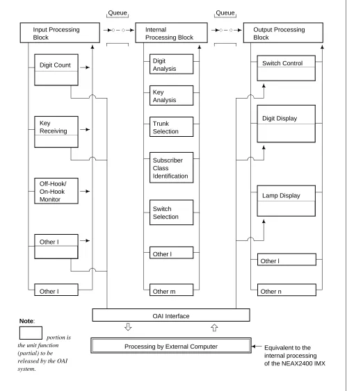
Note: International Organization for Standardization (ISO) 2.2 Software Structure in the OAI System
SYSTEM OUTLINE System Outline
Figure 2-1 Software Structure in the OAI System Input Processing Block Digit Count Key Receiving Other I Off-Hook/ On-Hook Monitor Other I Queue Internal Processing Block Digit Analysis Queue Key Analysis Trunk Selection Subscriber Class Identification Switch Selection Other l
Other m Other n
Other l Output Processing Block Switch Control Digit Display Lamp Display OAI Interface
Processing by External Computer
portion is the unit function (partial) to be released by the OAI system.
SYSTEM OUTLINE System Outline
2.2.1 Facilities
Each of the unit functions of the NEAX2400 IMX, such as switch control function, terminal control function, etc., that can be controlled by the application of the computer is referred to as “facility”. The facilities can be categorized in two kinds as per the operating pattern; one is “Provider Facility” and the other is “Performer Facility”.
• Provider Facility
A facility of this kind is capable of communicating with one Application Program (AP) on the computer, and executes start-up, etc. of an AP on the computer.
• Performer Facility
A facility of this kind is capable of communicating with plural application programs (AP) on the computer. It is activated from each AP as the common facility and executes required processing in accordance with the control information given from the AP.
Each of the main facilities is outlined in the following.
1. Provider Facilities
(a) Terminal Mode Set Facility (MSF)
With a specific key depressed on a terminal, this facility sets terminal mode. When terminal mode is set by this facility, a communication path is set up between the terminal and the AP on the computer. (Figure 2-2)
Figure 2-2 Concept of MSF Note: The external computer is referred to as the computer.
Key operation
Terminal (Dterm)
MSF NEAX2400 IMX
AP The Computer
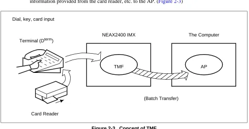
SYSTEM OUTLINE System Outline (b) Terminal Multiple Information Transfer Facility (TMF)
This facility executes batch transfer of dial number information entered from a terminal, card information provided from the card reader, etc. to the AP. (Figure 2-3)
Figure 2-3 Concept of TMF (c) Call Event Transfer Facility (ETF)
This facility edits the detailed data (call duration, etc.) pertaining to calls at terminals accommodated in the NEAX2400 IMX, and provides the edited information to the computer. (Figure 2-4)
Figure 2-4 Concept of ETF Dial, key, card input
Terminal (Dterm)
TMF NEAX2400 IMX
AP The Computer
(Batch Transfer)
Card Reader
Terminal (Dterm)
ETF NEAX2400 IMX
AP The Computer
SYSTEM OUTLINE System Outline
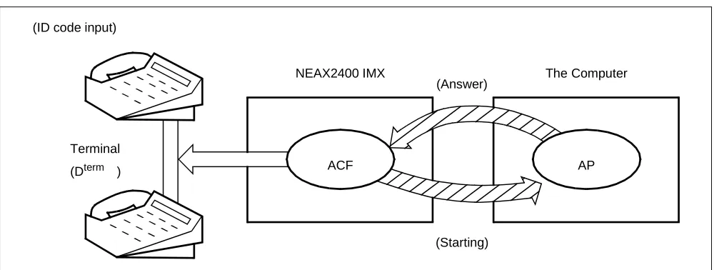
(d) Authorization Code Facility (ACF)
Upon accepting a connection request and/or a service request from a terminal, this facility transfers the ID code of that specific terminal to the AP and also executes either connection processing or connection restricting processing in accordance with the restriction class information returned from the computer. (Figure 2-5)
Figure 2-5 Concept of ACF (e) Free Location Facility (FLF)
This facility establishes the correspondence between the extension number allocated to a terminal and the user’s unique ID code in accordance with the number conversion information provided from the AP. (Figure 2-6)
Figure 2-6 Concept of FLF (ID code input)
ACF NEAX2400 IMX
AP The Computer
Terminal (Dterm )
(Answer)
(Starting) Note: Connection Processing or Connection Restricting Processing
FLF NEAX2400 IMX
AP The Computer
SYSTEM OUTLINE System Outline 2. Performer Facilities
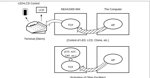
(a) Terminal Control Facility (TCF)
This facility controls the LCD, LED, etc. on a terminal concerned as per a control order provided by the AP. It also activates the KTF, NTF, and CRF upon receiving a data read request provided from the AP. (Figure 2-7)
Figure 2-7 Concept of TCF (b) Key Code Transfer Facility (KTF)
When a terminal concerned is on the terminal mode, this facility transfers the key code information from that specific terminal to the AP. (Figure 2-8)
Figure 2-8 Concept of KTF TCF
NEAX2400 IMX
AP The Computer
(KTF, NTF, CRF, etc.)
(Control of LED, LCD, Chime, etc.)
AP TCF
LCD
(Activation of Other Facilities) Terminal (Dterm)
LED•LCD Control
Terminal (Dterm)
KTF NEAX2400 IMX
AP The Computer
SYSTEM OUTLINE System Outline
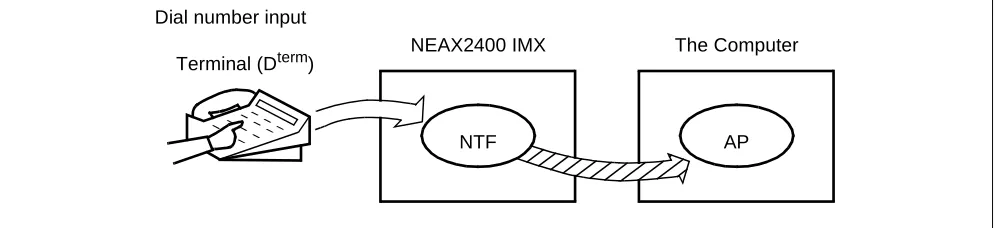
(c) Dial Number Transfer Facility (NTF)
When a terminal concerned is on the terminal mode, this facility transfers the dialed number information from that specific terminal to the AP. (Figure 2-9)
Figure 2-9 Concept of NTF
(d) Switch Control Facility (SCF)
This facility executes the processing of an outgoing connection or of releasing the connection between a terminal and another in accordance with the connection control information provided from the AP. (Figure 2-10)
Figure 2-10 Concept of SCF Dial number input
Terminal (Dterm)
NTF NEAX2400 IMX
AP The Computer
(Dial Number Information Transfer)
SCF
NEAX2400 IMX The Computer
(Processing of Outgoing Connection/Connection Release) Terminal (Dterm)
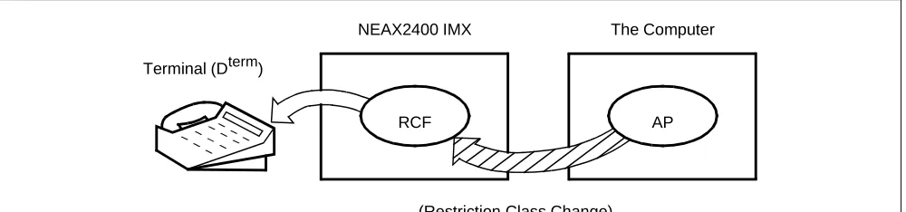
SYSTEM OUTLINE System Outline (e) Restriction Control Facility (RCF)
This facility changes the restriction class of a terminal concerned in accordance with a directive given by the AP. The restriction class changing can be made on the basis of each terminal, each group, or each system. (Figure 2-11)
Figure 2-11 Concept of RCF
(f) Terminal Mode Reset Facility (MRF)
With a direction received from the AP or a specific key depressed on a terminal, this facility resets terminal mode. When terminal mode is reset by this facility, the current communication path (terminal mode status) is released. (Figure 2-12)
Figure 2-12 Concept of MRF RCF
NEAX2400 IMX
AP The Computer
(Restriction Class Change) Terminal (Dterm)
Terminal (Dterm)
MRF NEAX2400 IMX
AP The Computer Key operation
SYSTEM OUTLINE System Outline
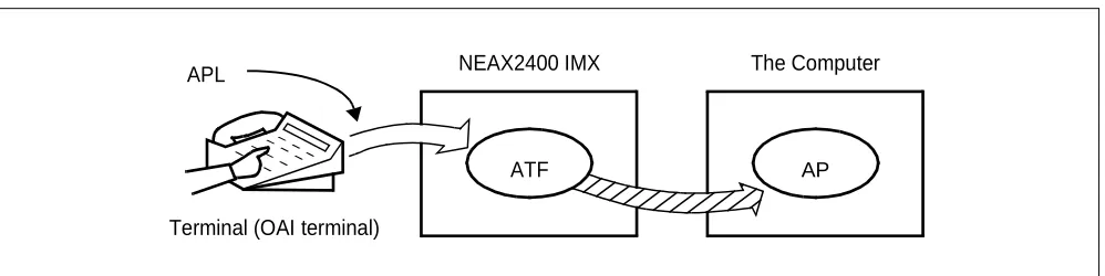
(g) Application Language Transfer Facility (ATF)
With a direction received from the AP or a specific key depressed on a terminal, this facility sends out the APL information input from an OAI terminal to the AP. (Figure 2-13)
The system does not care the contents of the APL information at all.
Figure 2-13 Concept of ATF Terminal (OAI terminal)
ATF NEAX2400 IMX
SYSTEM OUTLINE System Outline 2.2.2 Join of Facilities and Application
1. When a facility of the NEAX2400 IMX is controlled by the Application Program (AP) on the UAP computer, the AP and that facility must be connected first. The following is the procedure of this connection.
(a) Set-up of Association
A communication path is to be opened so that the AP can communicate with the facility.
(b) Opening of Facility
The facility that the AP uses is to be declared to the NEAX2400 IMX, and then the AP and the declared facility are joined.
2. Set-up of Association and Opening of Facility
Association is set up by activation from the AP first, and then the association is released along with the stop of the AP. Without this association, the AP cannot communicate with the facility and cannot control the facility, either.
Then, the facility must be opened so as to allow the AP to communicate with the facility through the communication path opened by setting up of the association. Opening of facility is executed on each facility basis.
As a result of the above procedure, the AP becomes able to freely control each of the facilities of the NEAX2400 IMX, and a variety of applications can be programmed on the computer.
2.2.3 Cope of Application in changeover of CPU System
Associations established between NEAX2400 IMX and External computer are released when changeover of CPU system executes.
SYSTEM OUTLINE System Configuration
3. System Configuration
The OAI System can be implemented in the Built-in Type configuration, with which the IP is built in the CPU of the NEAX2400 IMX. The configuration of the NEAX2400 IMX OAI System is as follows.
IP
External Computer Interface Circuit
Ether: TCP/IP Built-in CPU
Provided with External LAN cable connected from the PBX
OAI System
Single CPU configuration (Figure 2-14)
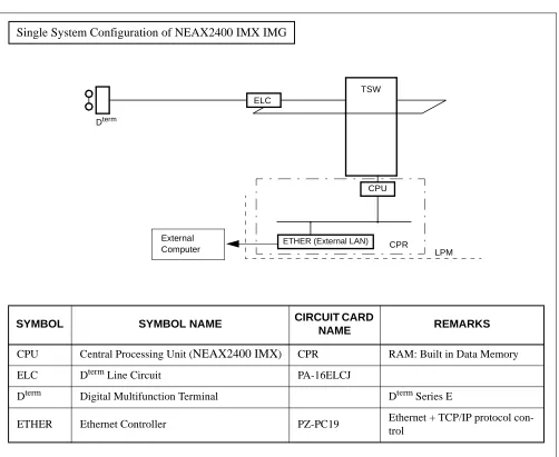
SYSTEM OUTLINE System Configuration 1. The configuration of the NEAX2400 IMX OAI System is as follows.
Figure 2-14 IP Single System Configuration Single System Configuration of NEAX2400 IMX IMG
SYMBOL SYMBOL NAME CIRCUIT CARD
NAME REMARKS
CPU Central Processing Unit (NEAX2400 IMX) CPR RAM: Built in Data Memory
ELC Dterm Line Circuit PA-16ELCJ
Dterm Digital Multifunction Terminal Dterm Series E
ETHER Ethernet Controller PZ-PC19 Ethernet + TCP/IP protocol con-trol
ELC
TSW
CPU Dterm
ETHER (External LAN) CPR
LPM External
SYSTEM OUTLINE System Configuration
Figure 2-15 IP Dual System Configuration Dual System Configuration of NEAX2400 IMX IMG
SYMBOL SYMBOL NAME CIRCUIT CARD
NAME REMARKS
CPU Central Processing Unit (NEAX2400 IMX) CPR RAM: Built in Data Memory
ELC Dterm Line Circuit PA-16ELCJ
Dterm Digital Multifunction Terminal Dterm Series E
ETHER Ethernet Controller PZ-PC19 Ethernet + TCP/IP protocol con-trol
ELC
CPU Dterm
ETHER (External LAN)
TSW
CPR External
SYSTEM OUTLINE Interface with External Computer 4. Interface with External Computer
4.1 Conditions for Interface with External Computer
The circuit card for interface with the external computer (general-purpose information processing equip-ment), and the interface conditions are shown in Table 2-1.
Note: 172. 16. 253. 0 (Default)
Table 2-1 Interface Conditions of the Circuit Card
CIRCUIT CARD INTERFACE CONDITIONS
ETHER (PZ-PC19)
Physical Interface 10BASE-T
Communication Protocol TCP/IP
Internet Address
1 address/system
(Class A, B, C is available Note)
TCP port 1 Port/Internet Address
60030
Data Transfer Speed 10 Mbps
CHAPTER 3
INSTALLATION PROCEDURE
1. General
This chapter explains the installation procedure for OAI System of NEAX2400 IMX.
• Cable Connections with External Computer • OAI Software Installation
INSTALLATION PROCEDURE
Cable Connections with External Computer
2. Cable Connections with External Computer
This section explains cable connections between the NEAX2400 IMX OAI System and the external computer.
2.1 Cable Connections between OAI System and External Computer
The cable connections between the OAI system and the external computer are shown in Figure 3-1.
[PZ-PC19 card (LANI) is used]
(a) Connection diagram
• When the OAI system and the external computer are connected using Ethernet + TCP/IP interface
Figure 3-1 Cable Connections Between OAI System and External Computer
ATTENTION Contents Static Sensitive Handling
Precautions Required
00 01 02 03 04 05 06 07 08 09 10 11
00 01 02 03 04 05 06 07 08 09 10 11
12 13 14 15 16 17 18 19 20 21 22 23
LANI (PZ-PC19)
External Computer
HUB BASEU
LPM
10BASE-T (Straight)
PH-PC40 (EMA)
INSTALLATION PROCEDURE OAI Software Installation 3. OAI Software Installation
This section explains the installation procedure for adding the OAI software to the PBX in off-line operation. For more detailed information of program install procedure before the OAI application software install, see “Installation Manual”.
[Operation Procedure]
STEP 1: By using MEM_HDD command, save all data to the both HDDs.
STEP 2: Make the Standard Service Software FD link with the OAI Option Service Software FD, and install it into the HDD.
When OAI system is used in the Fusion Network (OAI Terminal Anywhere), link the ACD Option Service Software for “Agent Anywhere” with the above software FD and install it into all the nodes. (valid since the PBX software R8)
STEP 3: Initialize the system (perform IPL, DM loading). PROGRAM=“LOAD”
SYSTEM DATA=“OVERRIDE/LOAD”
Note: When OAI system is used through the Fusion Network [valid since Series 7400 (Release 8) software], the UAP must be booted up after the confirmation of the establishment of the Fusion Link.
STEP 4: Change system data written in DM.
ASYD SYS1
INDEX31 - b0~b3: CM mounting capacity
Normally assign “04”. Note 1 Note 2 Note 3
INDEX79 - b6=0 (OAI service is in service) Note 1
INDEX207 - b0 (IP in system0), b1 (IP in system1)
Assign “1” to the corresponding bit for the IP accommodation. INDEX241- b2=1 (Call Processing Event Notification) Note 1
INDEX241- b3=1 (Details of SCF Error Notification) Note 1
Note 1: When OAI system is used in the Fusion Network, this data setting is necessary at the all nodes.
Note 2: Reset the system after changing this data from 02H (normally assigned data value for the system without OAI service) to 04H.
STEP 5: Assign the system data written in NDM.
This data below are necessary when OAI system is used through the Fusion Network.
ASYDN SYS1
INDEX514- NDM usage
INDEX533- FPC of the node that provides VNDM (Normally, assign the FPC of the node that has the IP)
INSTALLATION PROCEDURE OAI Software Installation
STEP 6: Assign the system data written in LDM.
ASYDL SYS1
INDEX512: FPC of the self-node
When OAI system is used through the Fusion Network, this data setting is necessary at each node in the network.
INDEX513: 01 Hex (LDM usage)
INDEX515~518 b0~b7: IP address (Hex) for PBX over external LAN Note 4
INDEX519~522 b0~b7: Subnet Mask (Hex) for PBX over external LAN Note 4
INDEX523~526 b0~b7: Default Gateway Address for External LAN Note 4
(This data is required when the Host is connected via gateway)
INDEX864 - b0=1 (Built-in IP is provided)
When OAI system is used in the Fusion Network (OAI Terminal Anywhere) [available since the Series 7400 (Release 8) software], assign “1” at the node that has the IP.
INDEX864 b1 :Output the system message (4-R) when TCP-IP is normally disconnected. 0/1=Effective/Ineffective
Note 4: If the MAT or SMDR has been connected with external LAN already, this data assignment is not necessary. STEP 7: Check the station-to-station connection and confirm no fault status occurs or system messages are output (such as cable connection fault, LCD display fault, memory alarm fault, abnormal interrupt etc.).
STEP 8: Program the OAI office data. Also, program the Fusion data to make ACD service effective through Fusion network, if necessary.
INSTALLATION PROCEDURE Upgrading OAI System from NEAX2400 ICS to NEAX2400 IMX 4. Upgrading OAI System from NEAX2400 ICS to NEAX2400 IMX
The procedure for upgrading OAI System NEAX2400 ICS to NEAX2400 IMX is shown below.
4.1 Up Grading Procedure
STEP 1: Stop the operation of the external computer by the appropriate procedure.
STEP 2: Upgrade the PBX hardware following by the Upgrade Manual for the PBX.
STEP 3: Upgrade the PBX software to install the software below.
• Assortment of software for NEAX2400 IMX Note 1
• OAI Optional software
STEP 4: Program the following OAI commands data again.
• ASYDL Note 2
STEP 5: Start Up the external computer Note 3
• hardware and software of the external computer
STEP 6: Perform the installation test.
Note 1: This software is commonly used with all types of systems. Data Memory does not have to be changed. Note 2: For detail, see Section 3. “OAI Software Installation”.
CHAPTER 4
COMMANDS
1. General
This chapter explains the commands that are used in the NEAX2400 IMX OAI System. The contents of this Chapter are outlined below.
• Configuration of Commands for OAI System
This section explains the construction of each command.
• Commands
COMMANDS
Configuration of Commands for OAI System
2. Configuration of Commands for OAI System
2.1 Configuration of Commands
The configuration of the commands in use in the NEAX2400 IMX OAI System is shown in Figure 4-1.
Figure 4-1 Configuration of Commands of the NEAX2400 IMX OAI System Commands for
Business
Commands for OAI System
ASYDL AKYD ARNP ASPA
AADT ACNO AMNO AOAC AOKC LADT LCNO
LMNO LOAC LOKC DFLN OAI System Operating Commands
Commands ASYD
COMMANDS Commands 3. Commands
This section explains the commands in used in the OAI System.
3.1 List of Commands
Table 4-1 shows a list of commands in use in the OAI system. As for any command other than those in the list, refer to the Feature Programming Manual and Office Data Specification of the NEAX2400 IMX.
Note 1: Each command marked with * is used for listing up the assigned data, and thus its explanation will be omitted.
Note 2: For this command, refer to the Feature Programming Manual and Office Data Specification of the NEAX2400 IMX.
Table 4-1 OAI System Command Table List ABBREV.
COMMAND COMMAND
AADT Assignment of Announcement/Dictation Trunks
ACNO Assignment of Conversion Number Data
AKYD Assignment of Key Data for Dterm
AMNO Assignment of Monitored Number
AOAC Assignment of OAI Access Code
AOKC Assignment of OAI Key Code
ARNP Note 2 Assignment of Reverse Numbering Plan Data ASPA Assignment of Specific Attendant Number ASYD
ASYDN
ASYDL
Assignment of System Data
DFLN Display of Location Free Numbering
COMMANDS Commands
3.2 Outline of Commands for OAI System
The interrelation among the commands to be used in the OAI System is illustrated in Figure 4-2.
Figure 4-2 Interrelation among OAI System Commands
AKYD: This command is used to assign the function key codes (For OAI: 34 ~ 47) to the function key positions of the Dterm.
AOKC : This command is used to assign the meaning of OAI key code assigned by AKYD command.
Note 1: Function key codes 34 ~ 47 respectively correspond to OAI key codes (1 ~ 14).
AOAC : This command is used to assign the access code/operation code for the designated facility. This command is used only when the Facility Kind (F-KIND) has been set to “3” (Open Appli-cation Interface) by AOKC command.
Note 2: Parameters OAI Key Code (KEY-CODE), Facility Kind (F-KIND), and Operation Code (OP-CODE) are determined by the application software to be used at each office.
3.3 Items to Be Explained by Each Command Each command is described by the following items.
Command : The name implies the command and its functions. (1) Functions : This item outlines the command functions.
(2) Precaution : This item explains precaution for use of the command.
(3) Parameters : This item explains the meaning of the information (parameters) of the data of the command.
(4) Related Commands : This item specifies other command or commands pertaining to the same data, assignment/deletion/change/display/list up of the details of that specific data. NEAX2400 IMX
DLC/ELC
AKYD AOKC AOAC
ASDT AKYD
External Computer
ASYD ARNP
IP
Command Name : Commands for NEAX2400 ASYD
ARNP ASDT AKYD
: Assignment of System Data
: Assignment of Reverse Numbering Plan Data : Assignment of Station Data
COMMANDS AADT
AADT: Assignment of Announcement/Dictation Trunks
1. Functions
This command is used to assign/delete Announcement Trunks or Dictation Trunks.
2. Precaution
When changing the LENS of the currently assigned Announcement/Dictation Trunks, delete the assigned data first by this command, and then change the LENS by Assignment of Trunk Data (ATRK) command. It must be remembered that, if the LENS data are deleted first by ATRK command by mistake, the data currently assigned by this AADT command are automatically deleted.
3. Parameters
TYPE : Announcement Trunk (ANT), Dictation Trunk (DCT)
NO. : Message Number
D : Disconnect Timer (0/1); Valid when TYPE = ANT 0: Impossible (Repeat)
1: Possible (Disconnect by MSGT)
MSGT : Message Timer (2 ~ 120 sec., 2-sec. interval when shorter than 30 sec., 8-sec. interval when longer than 30 sec.)
CP : Connection Pattern Note
0: Multiple Connection 1: Single Connection
WAIT : Waiting Timer (0~30 sec., 2-sec. interval) Note
Note: Available only when the system data is programmed that the DAT control function is available (ASYD, SYS1, INDEX449, b2=1).
CNT : Number of ANT/DCT Trunks assigned or to be assigned (1 ~ 8)
RT : Route Number
TK : Trunk Number
4. Related Commands
COMMANDS AADT
Announcement/Dictation Trunk Data Assignment Table
Disconnect Timer 0 = Impossible 1 = Possible TRUNK TYPE (TYPE) ANT/DCT MESSAGE NO. (NO) MESSAGE TIMER (MSGT) 2 ~ 120
DISCON-NECT TIMER (D) 0/1 CONNEC-TION PATTERN (CP) 0/1 WAITING TIMER (WAIT)
0 ~ 30
ANT/DCT ASSIGNED
NO. OF TRUNKS (CNT)
1 ~ 8
ROUTE NUMBER (RT) TRUNK NUMBER (TK) ANT
1 ~ 58 DCT 1 ~ 5
COMMANDS ACNO
ACNO: Assignment of Conversion Number Data
5. Functions
This command is used to assign/delete the conversion number required for selecting a route on a each route basis.
6. Precaution
(a) The data should be assigned to ring-down trunks.
(b) As a conversion number, a monitor number assigned by AMNO command should be set.
7. Parameters
RT : External Route Number
TN : Tenant Number of Monitored Number MNO : Monitored Number (Max. 5 digits) Note
Note: Max. 6 digits when using in a hotel system 8. Related Commands
Monitored Number Assignment: AMNO – Parameter RT –
Monitored Number Deletion : AMNO Assignment : ARTD
List Up : LCNO Display : ARTD
COMMANDS ACNO
Conversion Number Data Assignment Table
Note: Max. 6 digits when using in a hotel system EXTERNAL ROUTE NUMBER
(RT)
TENANT NUMBER OF MONITORED NUMBER
(TN)
MONITORED NUMBER (MNO)
COMMANDS AKYD
AKYD: Assignment of Key Data for D
term9. Functions
This command is used to assign/delete/display the function key data, multi-line data or intercom data corresponding to each key on such multi-function telephone terminal as Dterm Series E.
10. Precaution
For the details of Dterm data, refer to the description of AKYD command in the Feature Programming Manual and Office Data Specification for the NEAX2400 IMX. Explanations here will be limited only to the items pertaining to the OAI System.
11. Parameters
FKY: Function Key (valid for KYI=1)
34= OAI Key 1
35= OAI Key 2
36= OAI Key 3
37= OAI Key 4
38= OAI Key 5
39= OAI Key 6
40= OAI Key 7
41= OAI Key 8
42= OAI Key 9
43= OAI Key 10
44= OAI Key 11
45= OAI Key 12
46= OAI Key 13
47= OAI Key 14
52= Speaker
59= Release
COMMANDS AMNO
AMNO: Assignment of Monitored Number
12. Functions
This command is used to assign/delete Monitored Numbers.
13. Precaution
Monitored Number (MON) is a number of maximum 5 digits consisting of 0 ~ 9, “*” and “#”.
Note that, in the case of a hotel system, UCD Pilot Number (STN) is a number of maximum 6 digits, respectively.
As NMI value, use a different value for each MON to be assigned.
14. Parameters
TN : Tenant Number
MNO : Monitored Number (Max. 5 digits) NMI : Monitored Number Index (1 ~ 4095)
UCD : Going by UCD when monitor status is not requested from AP 0: Not going by UCD
1: Going by UCD
STN : UCD Pilot Number (Max. 5 digits) Note [In the case of Hotel System]
A/G : Designation of Administration/Guest Room A: For Administration
G: For Guest Room
Note: Maximum 6 digits when using in a hotel system 15. Related Commands
COMMANDS AMNO Monitored Number Assignment Table
Note 1: Max. 6 digits when using in a hotel system Note 2: Data to be entered for a hotel system
Going by UCD when monitored status is not requested from AP :0/1 = Not Going By UCD/Going By UCD. TENANT NUMBER (TN) MONITORED NUMBER (MNO) MAX. 5 DIGITS
(Note 1)
MONITORED NUMBER INDEX
(NMI) 1 ~ 4095
GOING BY UCD WHEN MONITOR STATUS IS NOT REQUESTED FROM AP (UCD) 0/1 UCD PILOT NUMBER (STN) MAX. 5 DIGIT
(Note 1)
DESIGNATION OF ADMINISTRATION/
GUEST ROOM (A: FOR ADMINI
G: FOR GUEST ROOM)
(Note 2)
COMMANDS AOAC
AOAC: Assignment of OAI Access Code
16. Functions
This command is used to assign/delete the Facility Kind and the Operation Code on a basis of each service access code of the OAI System.
17. Precaution
(a) When setting a minus value (less than 0) to the parameter “OP-CODE”, add “-” (minus symbol) ahead to the value.
If the set value is a positive value, it is automatically interpreted to be a positive value even if “+” (plus symbol) is not added ahead of the value.
(b) For assigning OAI access codes, it is necessary to assign the necessary number of digits of OAI access codes by AOKC command in advance to assigning the codes.
18. Parameters
OAI-ACC : OAI Access Codes (000 ~ ###) (Max. 3 digits) F-KIND : Facility Kind (1 ~ 15)
1: Terminal Mode Set Facility (MSF)
2: Terminal Multiple Information Transfer Facility (TMF) 3:
Not used 15:
OP-CODE : Operation Codes (128~ 255) When F-KIND = 1, 128 ~ 191 When F-KIND = 2, 192 ~ 255
19. Related Command
COMMANDS AOAC OAI Access Code Data Assignment Table
Note: The number of digits for OAI Access Codes is to be set by AOKC command. OAI ACCESS CODE
(MAX 3 DIGITS) (OAI-ACC)
FACILITY KIND (1/2) (F-KIND)
COMMANDS AOKC
AOKC: Assignment of OAI Key Code
20. Functions
This command is used to assign/delete the Facility Kind and the Operation Code on a basis of each function key on the Dterm.
21. Precaution
(a) The OAI code for which F-KIND = 3 (Open Application Interface) can be assigned is only one per system.
(b) When deleting the Open Application Interface (OAI) key code for which F-KIND = 3 is assigned, it is necessary, in advance to the intended deletion, to delete all the OAI access code data assigned by AOAC.
(c) When OAI key data has been assigned/deleted on basis of a function key by this command, operation of the OAI key is ignored only once immediately after that assignment/deletion or immediately after a system initialization.
22. Parameters
KEY-CODE: OAI Key Codes (1 ~ 31) Note 1
F-KIND : Facility Kind (1 ~ 15)
1: Terminal Mode Set Facility (MSF)
2: Terminal Multiple Information Transfer Facility (TMF) 3: Open Application Interface (OAI)
4: Key Code Transfer Facility (KTF) 5.
Not used 15:
C-TONE : Chime control on normal end of MSF, TMF, and OAI 0: To be controlled
1: Not to be controlled (No Tone)
NND : Necessary Number of Digits (1 ~ 3) Note 2
OP-CODE : Operation Codes Note 3
(128 ~ 255) Operation Codes
128 (0080)H: MSF
OAI
(Terminal Mode Set Facility)
191 (00BF)H: MSF
192 (00C0)H: TMF
OAI
(Terminal Multiple Information Transfer Facility)
COMMANDS AOKC Note 1: The relationship between this parameter and the AKYD command parameter FKY = 34 ~ 47 is shown
below.
Note 2: Enter this parameter only when F-KIND = 3.
Note 3: This parameter can be entered only when F-KIND = 1, 2. The range of the values that can be entered is as follows:
F-KIND = 1: OP-CODE = 128 ~ 191 F-KIND = 2: OP-CODE = 192 ~ 255
23. Related Commands
List Up: LOKC
PARAMETER KEY CODE AKYD COMMAND
PARAMETER FKY
1 2 3 4 5 6 7 8 9 10 11 12 13 14 15 ~ 31
COMMANDS AOKC
OAI Key Code Data Assignment Table
Note 1: This parameter is to be entered only when F-KIND = 3. Note 2: This parameter is to be entered only when F-KIND = 1, 2.
Note 3: The KEY-CODE for which F-KIND = 3 can be assigned is only one per system.
Note 4: When deleting a Key-Code assigned on F-KIND = 3, it is necessary to delete all the Key-Code data before-hand by Assignment of OAI Access Code Data (AOAC) command.
OAI KEY CODE (1 ~ 31) (KEY-CODE)
FACILITY KIND (1 ~ 15) (F-KIND)
NECESSARY NUMBER OF DIGITS
(1 ~ 3) (NND) (Note 1)
OPERATION CODE
(128 ~ 255) (OP-CODE) (Note 2)
CHIME CONTROL ON NOR-MAL END OF MSF, TMF
COMMANDS AOKC
Table of Operation Codes
OPERATION CODE REMARKS
128 (0080): MSF
191 (00BF): MSF
OAI
(Terminal Mode Set Facility) 192 (00C0): TMF
255 (00FF): TMF
OAI
COMMANDS ASPA
ASPA: Assignment of Specific Access Code
24. Functions
This command is used to assign/delete/display each data which respectively determines what kind of service should be executed and/or which route should be used, etc. when a special access code, C.O. line access code or Tie-Line access code has been dialed.
25. Precaution
(a) For the details of special access code data, refer to the description of ASPA command in the Feature Programming Manual and Office Data Specification for the NEAX2400 IMX. Explanations here will be limited only to the items pertaining to the OAI System.
(b) For assigning OAI Dial Number Batch Transfer (SRV = SSCA, SIDA = 69), be sure to set the number of digits (max. 3 digits) of the OAI access code to Necessary Number of Digits (NND).
26. Parameters
SIDA: Service Feature Index A (69)
69: OAI Dial Number Batch Transfer (TMF)
Note: For the details of other parameters, refer to the description of ASPA command in the Office Data Specification for the NEAX2400 IMX.
Specific Access Code Data Assign Table
The Office Data Sheets of this ASPA command are attached only to the pages pertaining to the data to be assigned in the OAI System. Replace these Office Data Sheets with those for ASPA command of the NEAX2400 IMX.
Table 4-2 Supplementary Service Codes TENANT NUMBER (TN) ACCESS CODE (ACC) CONNECTION STATUS INDEX (CI) KIND OF SERVICE
(SRV) SERVICE
FEA-TURE INDEX A (SIDA)
REMARKS 1 ~ 31 1 ~ 3
DIGITS N/H/B SSCA
N Normal
SSCA 69 OAI Dial Number Batch
COMMANDS ASYD
ASYD: Assignment of System Data
27. Functions
This command is used to assign System Data 1, 2, and 3.
28. Precaution
COMMANDS ASYD
System Data Assign Table (1)
The Office Data Sheets of this ASYD command are provided only for the data to be assigned in the OAI System. Use these Office Data Sheets together with those for ASYD command of the NEAX2400 IMX.
SYSTEM DATA TYPE (SYS) SYSTEM DATA INDEX (INDEX) 0 – 255
DATA (DATA) 00– FF (Hex) BIT CORRE-SPONDING
DATA SYSTEM DATA CONTENTS
DATA
0/1 BIT
1
19
0 b0
Not used
0 b1
0 b2
0 b3
0 b4
b5
Call Event Transfer Facility (ETF) Call Base Table Save and ETF Ser-vice is provided
0/1: Unrequired/Required (3 hours) 0 b6 Fixed to 0
0 b7 Not used
28
b0 Miscellaneous Timer Counter (MTC)
(00 ~ 1F Hex)
Message sending Guard Timer for Message Center Interface.
Guard Time after sending data to Message Center: Time Value Setting is (MTC) × 128 msec. (When this data is 00 Hex, Timer value is 0 msec.) b1
b2 b3
b4
b5
Be sure to set “1” when using SSFR (FN = 5, SRID = 0) MCI Message Waiting Lamp Function
0/1: Not provided/Provided
0 b6
Not used
COMMANDS ASYD System Data Assign Table (1)
SYSTEM DATA TYPE (SYS) SYSTEM DATA INDEX (INDEX) 0 – 255
DATA (DATA) 00– FF (Hex) BIT CORRE-SPONDING
DATA SYSTEM DATA CONTENTS
DATA
0/1 BIT
1
31 04
0 b0 Equipped capacity of the Common Memory (CM): 1 ~ 4 Mbyte
Assign “6” Hex. when FLF Fusion service is used. (Available since the PBX software R8)
0 b1
1 b2
0 b3
0 b4
Not used
0 b5
0 b6
0 b7
47
b0 Traffic Measurement Indication 0/1 = CCS Indication/Erlang Indication
b1
Timer Internal Between Messages (TCFI) Timer
b2
0 b3
Display for TCFD 0/1 = MSG/Last input 0 = Normal assignment
0 b4 SCF(FN = 127) Tone Control 0/1 = Invalid/Valid
0 b5
Not used
0 b6
b7 Traffic Measurement for Terminal and Route Traffic (ATRF) 0/1 = Out/In service
b2 b1 b2 b1
COMMANDS ASYD
1
70
b0 Called Number Display when forwarding to Attendant Console 0/1 : Out/In service
b1 Flashing display of Line Lockout on Attendant Console BLF 0/1 : In service/Out
b2
Route No. Display on Attendant Console
b3
0 b4 One digit dialing instead of SHF (DP TEL only) 0/1 : Not required/Required
b5
Priority order for answering via ANSWER key 0 : Priority according to Type of Call
1 : Priority according to the order call termination
b6 Connection of SCF Announcement 1 : available
b7
Send Warning Tone to interrupted parties when Executive Right of Way service is in operation
0/1 : Required/Not required
77
b0 Day/Night Mode Change via the ATTCON Handset Jack 0/1: Not required/Required
0 b1 Not used
b2 MW Refresh 0/1 :Not required/Required
b3 Service Module Interface 0/1: Not required/Required 1 b4 Module in which PFT card is mounted
PIM (Always assign “11”)
1 b5
0 b6
Not used
0 b7
System Data Assign Table (1)
SYSTEM DATA TYPE (SYS) SYSTEM DATA INDEX (INDEX) 0 – 255
DATA (DATA) 00– FF (Hex) BIT CORRE-SPONDING
DATA SYSTEM DATA CONTENTS
DATA
0/1 BIT
b3 b2
0 0:
TN RT TRK
b3 b2
0 1:
COMMANDS ASYD
Note 1: When the bit is set to “0” the bottom line display of the Message Waiting Enhance Display Service becomes invalid.
Note 2: If, at an office in service with this bit set to “1” (No OAI Service is Provided), the bit value is to be changed to “0” (OAI Service is Provided).
1
78
1 b0
Calling and Intermediate Station Number indication (Dterm and ATTCON)
0/1: Out/In service (Always assign “1”)
1 b1
Kind of Service Class indication (Dterm) 0/1: Out/In service
(Always assign “1”) 0 b2 Not used
b3 Station Number Display with 8-digit Name Display 0/1: Out/In service
0 b4 Fixed to “0”
b5
Name Display Service
0/1: Not to be serviced/To be serviced (FLF: Free Location Facility)
0 b6
Not used
0 b7
79
b0 Line Preference Service via AKYD 0/1: Out/In service
0 b1 Not used
b2 Split Call Forwarding Service 0/1: Out/In service
0 b3 Not used
b4 Zip tone control at the time of SC F:Monitor connection 0/1: Not to be controlled/To be controlled
b5 Name Display Service for Calling Party Only 0/1: Out/In service Note 1
b6 OAI Service
0/1: In/Out service Note 2
0 b7 Not used
System Data Assign Table (1)
SYSTEM DATA TYPE (SYS) SYSTEM DATA INDEX (INDEX) 0 – 255
DATA (DATA) 00– FF (Hex) BIT CORRE-SPONDING
DATA SYSTEM DATA CONTENTS
DATA
COMMANDS ASYD
System Data Assign Table (1)
SYSTEM DATA TYPE (SYS)
SYSTEM DATA INDEX (INDEX) 0 – 255
DATA (DATA) 00– FF (Hex)
BIT CORRE-SPONDING
DATA SYSTEM DATA CONTENTS
DATA
0/1 BIT
1 80
0 b0 Not used
b1 Message Reminder Service-Key used for Message Deletion (D term) 0/1 = # key/* key
b2 Fixed to “0”
b3
TCF (I) : LCD Display Control 0: Top Line 16-digits display control 1: Second Line 16-digits display control
0 b4
Not used
0 b5
0 b6
COMMANDS ASYD System Data Assign Table (1)
SYSTEM DATA TYPE (SYS)
SYSTEM DATA INDEX (INDEX) 0 – 255
DATA (DATA) 00– FF (Hex)
BIT CORRE-SPONDING
DATA SYSTEM DATA CONTENTS
DATA
0/1 BIT
1 207
b0 No. 0 CPU Mounted Status of IP00/1:Not mounted/Mounted b1 No. 1 CPU Mounted Status of IP00/1:Not mounted/Mounted
0 b2
Not used
0 b3
0 b4
0 b5
0 b6
COMMANDS ASYD
Note: This timer data is exclusively for the function for batch transfer (TMF) of OAI dial number from a single-line telephone set. Therefore, this timer data is invalid for TMF from a Dterm.
1
241
b0 Data Port Chime Control by SCF 0/1: To be controlled/Not to be controlled
b1 Name Display Service 0/1: 8 digits/16 digits
b2 Call Status Monitor Facility Notification (SMFN) 0/1: Invalid/Valid
b3 SCF Return Error Detail Notification 0/1: Invalid/Valid
0 b4
Not used
0 b5
0 b6
0 b7
251
b0 Miscellaneous Timer Counter (MTC)
1 ~ F
Value for OAI Host Computer Answer Wait Timer (TC) × (MTC) is to be set.
When the data is 00 (Hex), the timer value becomes 8 minutes. Note
b1 b2 b3
b4 Timer Class (TC)
0: – 3: 2 sec.6:– 1: 64 msec. 4: 30 sec.7:–
2: – 5: –
b5 b6
0 b7 Not used
System Data Assign Table (1)
SYSTEM DATA TYPE (SYS) SYSTEM DATA INDEX (INDEX) 0 – 255
DATA (DATA) 00– FF (Hex) BIT CORRE-SPONDING
DATA SYSTEM DATA CONTENTS
DATA
COMMANDS ASYD System Data Assign Table (1)
SYSTEM DATA TYPE (SYS)
SYSTEM DATA INDEX (INDEX) 0 – 255
DATA (DATA) 00– FF (Hex)
BIT CORRE-SPONDING
DATA SYSTEM DATA CONTENTS
DATA
0/1 BIT
449
b0 SCF Call origination from the first party notification 0/1 = Ineffective/Effective
b1 Not used
b2 Access to Announcement trunk is controlled: 0 = by the timer, 1 = by the DAT
b3 Output pattern of INS information by SMFN 0/1: HEX/ASCII
b4
Not used b5
COMMANDS ASYD
System Data Assign Table (3)
SYSTEM DATA TYPE (SYS)
SYSTEM DATA INDEX (INDEX) 0 – 255
DATA (DATA) 00– FF (Hex)
BIT CORRE-SPONDING
DATA SYSTEM DATA CONTENTS
DATA
0/1 BIT
3 15
b0 Designation of the initial mode of the card reader
000: PB Sender 100
001: LP Command : Not used
010: – 111
011: Data channel b1
b2
0 b3
Not used
0 b4
0 b5
0 b6
0 b7
COMMANDS DFLN
DFLN: Display of Location Free Numbering
29. Functions
This command is used to check the assigned data of Location Free Numbering Service. When this command is activated, the assigned data are displayed on a basis of each designated station number.
30. Precaution
The data to be displayed by this command are those assigned from the User Application Processor (UAP) and thus they cannot be assigned by a command.
31. Parameters
[Input Parameters]
F : Function Kind (0/1)
LSTN : Logical Station Number (ID-No. Max. 5 digits) Note 1
TN : Tenant Number Note 2
PSTN : Physical Station Number (Station Number) Note 2
[Display Parameters]
RSC : Route Restriction Class
SFC : Service Feature Restriction Class DC : Digit Code
Note 1: This parameter is to be entered/displayed only when F = 0. Note 2: These parameters are to be entered/displayed only when F = 1.
32. Related Commands
COMMANDS ASYDN
ASYDN: Assignment of System Data in NDM
33. Function
This command is used to assign system data 1 and 2.
34. Precautions
1. This section only explains about ASYDN command for OAI system. 2. For more details of ASYDN command, see the “Office Data Specification.”
35. Parameters
COMMANDS ASYDN
Note 1: When the all Fusion nodes in the network are used for “MULTIPLE IPs”, this data may be assigned using ASYDN.
Note 2: Available since the Series 7400 (Release 8) software. SYSTEM DATA TYPE (SYS) SYSTEM DATA INDEX (INDEX) 0 – 1535
DATA (DATA) 00 – FF (Hex)
BIT CORRESPONDING
DATA
SYSTEM DATA CONTENTS (MDATA)
DATA
0/1 BIT
1
514 01
b0 Network Data Memory (NDM) usage. Assign data “1 (the memory block is used)” for the corresponding memory block.
b1 b2 b3 b4 b5 b6 b7 533 b0
Set up Fusion Point Code (FPC) of Node which basic VNDM is mounted on. (1~253)
Note: OAI/ACD is available in used. VNDM = Variable Network Data Memory b1 b2 b3 b4 b5 b6 b7
864 b3 Multiple IPs 0/1 = Out/In Service Note 1
870
b0 FLF Fusion Service
0/1 = Invalid/Valid Note 2
b1 Not used b2 b3 b4 b5 b6 b7
bit Memory Block
b0 Memory Block #0 b1 Memory Block #1 b2 Memory Block #2
COMMANDS ASYDL
ASYDL: Assignment of System Data into Local DM (LDM)
36. Function
This command is used to assign and change system data for OAI activated via FCCS.
37. Precautions
ASYDL command is comprised with System Data-1, INDEX 512-1535. This section only explains about ASYDL command for OAI System.
38. Parameters
COMMANDS ASYDL SYSTEM DATA TYPE (SYS) SYSTEM DATA INDEX (INDEX) 512-1535 DATA (DATA) 00 – FF (Hex)
BIT CORRESPONDING
DATA
SYSTEM DATA CONTENTS DATA
0/1 BIT
1
512
b0 Fusion Point Code (FPC) of self node in hexadecimal. FPC 1-253 (01 Hex-FD Hex)
Note: After assigning/changing the FPC, System Initialization (Non-Load Initialization) is required.
b1 b2 b3 b4 b5 b6 b7 513 01
b0 Local Data Memory (LDM) usage. Assign data “1 (the memory block is used)” for the corresponding memory block.
b1 b2 b3 b4 b5 b6 b7 515
IP Address (Hex) for PBX over External LAN
Note: This data is valid when the PBX is connected to the external PC LAN.
When 172.16.253.0 (default IP address) for the PBX is used, this data setting is not necessary.
Example: IP Address : 133.206.8.1
516
517
518
519
Subnet Mask (Hex) for PBX over External LAN
Note: This data is valid when the PBX is connected to the external PC LAN.
When 172.16.253.0 (default IP address) for the PBX is used, this data setting is not necessary.
Example: Subnet Mask : 255.255.0.0
520
521
522
bit Memory Block
b0 Memory Block #0 b1 Memory Block #1 b2 Memory Block #2
INDEX Set Hex
515 85
516 CE
517 08
518 01
INDEX Set Hex
519 FF
520 FF
COMMANDS ASYDL
1
523
Default Gateway Address of External LAN
Gateway Address (IP address of Router) of Network connecting PBX.
Note: This data is valid when the PBX is connected to the external PC LAN.
In the case of no Network Gateway, assignment data is 00 Hex. in Index 523 through 526.
Example: Default Gateway Address : 133.206.8.254
524
525
526
SYSTEM DATA TYPE (SYS)
SYSTEM DATA INDEX (INDEX) 512-1535
DATA (DATA) 00 – FF (Hex)
BIT CORRESPONDING
DATA
SYSTEM DATA CONTENTS DATA
0/1 BIT
INDEX Set Hex
523 85
524 CE
525 08
CHAPTER 5
OFFICE DATA DESIGN
1. General
This chapter explains the procedure for setting the office data required in the NEAX2400 IMX OAI System. As for the office data setting procedure of the NEAX2400 IMX System itself, refer to the System Data Design Manual.
The description of this Chapter consists of the following contents.
• Procedure for Setting Basic Office Data for OAI System
This section explains the procedure for setting the basic office data of the OAI system.
• Procedure for Setting Office Data for OAI Services
OFFICE DATA DESIGN
Procedure for Setting Basic Office Data for OAI System
2. Procedure for Setting Basic Office Data for OAI System
The procedure for setting the office data for OAI system is explained in the following.
2.1 Data for OAI System
1. ASYD/ASYDL
ASYD-SYS1 INDEX31 - b0 ~ 3 : CM mounting capacity (Normally Assign “04”.) INDEX79 - b6 = 0 (OAI service is in service)
INDEX207 - b0 (IP in system 0), b1 (IP in system 1)
Assign “1” to the corresponding bit for the IP accommodation. INDEX241 - b2 = 1 (Call Processing Event Notification) INDEX241 - b3 = 1 (Details of SCF Error Notification)
ASYDL-SYS1 INDEX513 : 01 Hex (LDM usage)
INDEX515~518 : IP address (Hex) for PBX over External LAN INDEX519~522 : Subnet Mask (Hex) for PBX over External LAN INDEX523~526 : Default Gateway Address for External LAN (This data is required when the Host is connected via gateway) INDEX864 - b0 = 1 (Built-in IP is provided)
INDEX864 b1 : Output the system message (4-R) when TCP-IP is normally disconnected.
0/1 = Effective/Ineffective
2. ARNP (Reverse Numbering Plan Data)
OFFICE DATA DESIGN Procedure for Setting Basic Office Data for OAI System 2.2 Data for OAI Terminal
In the case of Dterm
1. ASDT (In the case of Business; Station Data), AASP (In the case of Hotel system; Station Data) Note 1
Assign station data
Voice Port: TEC12 Data Port: TEC13 (Normal setting for others)
Note 1: For ASDT/AASP command, refer to the Command Manual of the NEAX2400 IMX. 2. AKYD (Dterm Key Data)
Assign the function key data of Dterm
Assign FKY34– 47 to any positions of FKY 1–16. (Normal setting for others)
3. AOKC (OAI Key Code Data)
Assign the OAI key code data
OAI key code 1 ~ 14 respectively corresponds to FKY34 ~ 47 of AKYD
4. AOAC (OAI Access Code Data)
If necessary, assign OAI access code data when using “OAI key + Access code” system to activate the application by MSF/TMF
In the case of Single-Line Telephone
1. ASYD (System Data)
Assign OAI Host Computer Respond Wait Timer
2. ANPD (Numbering Plan Data)
Assign the minimum necessary number of digits for OAI Dial Number Continuous Transfer Code
Note 2
3. ASPA (Special Access Code Data)
Assign the OAI Dial Number Continuous Transfer Access Code SSCA: 69 (OAI Dial Number Continuous Transfer)
NND : Necessary Number of Digits of OAI access code (Max. 3 digits)
Note 2: For ANPD command, refer to the Command Manual of the NEAX2400 IMX. 4. AOAC (OAI Access Code Data)
OFFICE DATA DESIGN
Procedure for Setting Office Data for OAI Services
3. Procedure for Setting Office Data for OAI Services
This section explains the outline, using conditions, and office data setting procedure of the main OAI service functions.
3.1 Switch Control Facility (SCF) 3.1.1 Functional Outline
The SCF is the facility that executes, from the Application Program (AP), such control operations as connections/disconnections between NEAX2400 IMX-accommodate terminal (Dterm) and another, between a Dterm and a C.O. Line Outgoing/Incoming Trunk, etc. The SCF has several functions (FN), and explanations will be given in the following about “Basic Connecting Function (FN = 1) – Make Call (Automatic Answer)” which is one of the several functions.
Note: The basic connection function is a function which automatically set a terminal into an outgoing connection status. Responding to a connection request from the AP, both the calling terminal number and the call destination number can be designated.
NEAX2400 IMX Station Group
OFFICE DATA DESIGN Procedure for Setting Office Data for OAI Services 3.1.2 Using Conditions
1. Normal and abnormal operating sequences pertaining to the basic connection of the SCF are as described below.
[Normal Sequence]
(a) Upon receiving SCF start request from the AP, the NEAX2400 IMX judges the status (idle, busy, makebusy, etc.) of the designated calling terminal and destination terminal.
(b) If the calling terminal and the destination terminal are idle, the NEAX2400 IMX sends out Return Result to the AP, and places the calling terminal into an outgoing connection status and the destination terminal into ringing status.
These are the basic functions.
(c) When the destination terminal designated from the AP is a terminal in the NEAX2400 IMX and automatic answer is designated as the answer type, both the calling and destination terminals can be placed into speech status immediately from the status cited in (b) (After zip tone has been sent to both terminals, the terminals are placed into speech status.).
Note that this service function is valid only when the destination terminal is in line selection wait status and also automatic answer is designated as the answer type. In other words, if the destination terminal is in a status other than line selection wait status, the call is to be answered manually. Further, this service function is valid only when the destination terminal is a station (Dterm: Voice) among the SCF Make Call designations. In other words, if the call destination is a trunk, this service function does not work.
Destination Terminal Calling Terminal NEAX2400 Computer (AP)
SCF Activated
Return Result Terminal Check
Connection
OFFICE DATA DESIGN
Procedure for Setting Office Data for OAI Services [Abnormal Sequence]
(a) Upon receiving SCF start request from the AP, the NEAX2400 IMX judges the status (idle, busy, makebusy, etc.) of the designated calling terminal and destination terminal.
(b) If the calling terminal and the destination terminal are in a status other than idle, the NEAX2400 IMX sends out Return Error to the AP.
2. Only digital multifunction telephone (Dterm Series E) can be designated as a calling terminal.
Destination Terminal Calling Terminal NEAX2400 Computer (AP)
SCF Activated
Return Error Terminal Check
OFFICE DATA DESIGN Procedure for Setting Office Data for OAI Services 3.1.3 Data Programming
Assignment
1. ASYD (System Data) SYS1
INDEX 79
b6: 0 (OAI service is available)
2. AKYD (Dterm Key Data)
Restrict a call origination from the prime line of the terminal of which answer type is designated as automatic answer
S: Outgoing call from a prime line (0/1) 0/1: Allowed/Restricted
Deletion
1. AKYD (Dterm Key Data)
Cancel restriction on a call origination from the prime line of the terminal of which answer type is designated as automatic answer
S: Outgoing call from a prime line (0/1) 0/1: Allowed/Restricted
2. ASYD (System Data) SYS1
INDEX 79