DESIGN OF CARTESIAN FEEDBACK RF POWER AMPLIFIER FOR L-BAND FREQUENCY RANGE
J. S. Mandeep, A. Lokesh, S. I. S. Hassan, M. N. Mahmud and M. F. Ain
School of Electrical and Electronic Engineering Universiti Sains Malaysia
14300 Nibong Tebal, Pulau Pinang, Malaysia
Abstract—A phase-alignment system is used fully integrate a power amplifier, Cartesian feedback linearization circuitry, and a phase-alignment system. The phase-alignment system employs a new technique for offset-free analog multiplication that enables it to function without manual trimming. This paper demonstrates how the phase-alignment system improves the stability margins of the fully integrated Cartesian feedback system. The power amplifier itself, integrated on the same die, operates at 1 GHz and delivers a maximum of 30 dBm of output power into a 50-load. The class AB design for open loop and close loop power amplifier with Cartesian feedback, demonstrated a good linearity of 50 dBc and 80 dBc, respectively. The operating power is 2 W at 1000 MHz frequency.
1. INTRODUCTION
RF power amplifier is the basic component in any wireless transceiver so its efficiency directly influences the complete communications system [1–5]. Power amplifier can be classified as most power hungry blocks in a wireless transceiver system. Communication technology is slowly moving towards digital system. Digital technologies now being introduced can increase capacity two to five times compared with analogue system. However, the application of power amplifier will be critical for the digital modulation [11–16].
linearity. Power amplifier with high linearity has low efficiency [10, 18]. The level of power amplifier increases and the size becomes more compact, the lower efficiency causes severe thermal issue. Hence the efficiency of the amplifier has become an important issue.
If we apply a signal with a varying envelope to a power efficient non linear amplifier the performance of a radio communications system will be deteriorated in two ways [5]. Firstly, the distortion will make it more difficult for the receiver to correctly detect the information [5]. Secondly, as result of the inter-modulation distortion generated in the amplifier, the spectrum of the signal will expand into adjacent channel causing interferences for other users [5].
This paper discuss of designing a RF power amplifier operating power of 30 dBm and frequency of 1000 MHz for digital applications. The power amplifier has been linear using Cartesian Feedback method. The digital application is referred to digital modulation such as TETRA (Terrestial Trunked Radio —European Standard) which has a peak to average power of 3 dB ratio. Linear operating of power amplifier will ensure the operating power at allowable gain compression point and keep the inter-modulation distortion (IMD) within the requirement. Efficiency of the power amplifier will provide a good thermal solution. A proper bias method is taken into account to compromise the linearity and efficiency of the power amplifier.
2. DESIGN ANALYSIS
The design analysis for a PA basically requires dc network and impedance matching. DC network consists of dc feed and dc bias network. DC bias is to select the proper quiescent point and hold the quiescent point constant over variation in transistor and parameters and temperature. Basically, TETRA is a modulation that preserves amplitude and phase signal, therefore, class AB operation biasing is used here. DC feed line is important to prevent the RF from disturbing the dc supply lines. Impedance matching is necessary in PA design, in order to obtain maximum power transfer from source to its load.
3. CARTESIAN FEEDBACK SYSTEM
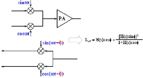
Typical Cartesian Feedback system is illustrated in Figures 1 and 2. Negative feedback is a basic concept behind this system. Cartesian feedback amplifiers are used to generate high output power signals with good adjacent-channel power ratios (ACPR). This is accomplish by coupling off part of the demodulated signal to pre-distort the input baseband I and Qsignals via comparator or filter circuit [17–22].
In detail, the demodulated signal I and Q at the output of the power amplifier are feedback to the summing input of comparator or filter circuit after 180 degrees of phase shift. The comparator or filter circuit will pre-distort its output to main virtual ground at the comparator’s summing node. This will occur when both inputs of the comparator circuit are in same phase when loop is open. When loop is closed, the input of the comparator or filter will be equal but in
Figure 1. Typical Cartesian feedback system.
different phase.
To get loop stability, the comparator circuit uses low pass filter circuit to limit loop bandwidth. The cut-off frequency must be sufficiently wider than the bandwidth spread due to the PA nonlinearity. This limits the upper modulation bandwidth, but is sufficient for mobile radio applications. Linearity is limited by two factors which are loop gain and the accuracy of feedback system.
The loop gain should as large as possible, but is limited by the loop stability, which in turn is closely dependent on phase response. Adjustment of the phase shifter is critical. With the loop opened, the phase should be adjusted so that there is no rotation of the demodulated I and Q signals with respect to the I and Q signal at the input of the comparator or filter circuit. The modulated signals are considered as sum [4]
A(t) sin(ωot+φ(t)) =I(t) sinωot+Q(t) cosωot (1)
where
I(t) = A(t) cosφ(t) (2)
Q(t) = A(t) sinφ(t) (3)
3.1. Phase Alignment in Cartesian Feedback System
Figure 1 shows a typical Cartesian feedback system. The loop driver amplifier is represented by the system block H(s) which provide the loop gain. The loop drivers feed the baseband inputs of the up-conversion mixer, which in turn drives the power amplifier. Coupling of the output of the power amplifier to the down-conversion mixer is employed. The output of the mixer is used to close the feedback system.
There are two identical decoupled feedback loops. One for the I signal component and the other one for Q signal component. This corresponds to the case where φ = 0 as shown in Figure 1. A Cartesian feedback system in which φ is non-zero said to have phase misalignment. In such case, the two feedback loops are coupled and the stability of the system is compromised. Phase misalignment has a major impact on system stability which can be derived mathematically. The demodulated signalS is rotated relative toS to an amount equal to the phase misalignment φ. The demodulated signals of Cartesian feedback can be expressed as follows [3].
whereω is carrier frequency
By applying trigonometric identities, Equations (4) and (5) can be written as
I = 1
2(Icosφ+Qsinφ) (6) Q = 1
2(−Isinφ+Qcosφ) (7) Here φ = 0. An excitation to the I input of the modulator results in a signal on the Q downconverter output. SimilarlyQ input of the modulator results in a signal on theI downconverter output. The two loops are coupled.
3.2. Cartesian Feedback Power Amplifier
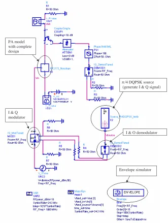
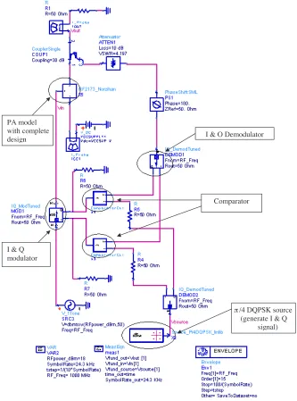
The inter-modulation distortion gives the quality of an amplifier to withstand multiple signals without generating large inter-modulation products or when using amplitude-modulated signals (cross modulation) [2]. For cellular phone systems, digital modulation formats such QPSK and π/4 DQPSK is used. These modulation types combine phase and amplitude modulation. Amplifiers handling such signals must be carefully characterized and designed if adequate amplitude and phase linearity are to be maintained [2]. This work presents modulation analysis usingπ/4 DQPSK in a 1000 MHz power amplifier. This amplifier is designed using Advanced Design System (ADS) to demonstrate the Adjacent Channel Power Ratio (ACPR).
A modulation source (π/4 DQPSK) is connected to the RF source at the input port of the amplifier. The source specifies the carrier power and the modulation source specifies the modulation format and properties of the modulated signal [2]. For open loop power simulation, harmonic balance simulator controller is used and envelope simulator controller for open loop ACPR. Refer to Figure 11 for open loop ACPR. Envelope simulator combines features of time and frequency domain representation, offering a fast and complete analysis of complex signals such as digitally modulated RF signals.
4. POWER AMPLIFIER SIMULATION ANALYSIS
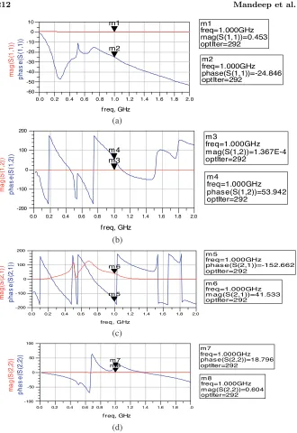
0.2 0.4 0.6 0.8 1.0 1.2 1.4 1.6 1.8 0.0 2.0 -50 -40 -30 -20 -10 0 -60 10
f req, GHz
m2 m1 m2 freq= phase(S(1,1))=-24.846 optIter=292 1.000GHz m1 freq= mag(S(1,1))=0.453 optIter=292 1.000GHz
0.2 0.4 0.6 0.8 1.0 1.2 1.4 1.6 1.8
0.0 2.0 -100 0 100 -200 200 freq, GHz m 4 m 3 m 3 freq= m ag(S(1,2))=1.367E-4 optIter=292 1.000GHz m 4 freq= phase(S(1,2))=53.942 optIter=292 1.000GHz
0.2 0.4 0.6 0.8 1.0 1.2 1.4 1.6 1.8
0.0 2.0 -100 0 100 -200 200 freq, GHz m 5 m 6 m 5 freq= phas e(S(2,1))=-152.662 optIter=292 1.000GHz m 6 freq= m ag(S(2,1))=41.533 optIter=292 1.000GHz
0.2 0.4 0.6 0.8 1.0 1.2 1.4 1.6 1.8
0.0 2 .0
-50 0 50
-100 100
f req, GHz m 7 m 8 m 7 freq= phas e(S(2,2))=18.796 optIter=292 1.000GHz m 8 freq= m ag(S(2,2))=0.604 optIter=292 1.000GHz m a g( S (1, 1 )) p h as e( S (1 ,1 )) m a g (S (1 ,2) ) p h as e( S (1 ,2 )) m a g (S (2, 1 )) p h as e( S (2 ,1 )) m a g (S (2,2) ) p h a s e (S (2,2) ) (a) (b) (c) (d)
dc biasing, dc feeds and impedance matching circuitry design must be done. In order to analyze the performance, DC and AC source was driven into PA device model. Hence the class of operation is set to class AB for optimum performance of linearity and efficiency. The following figures shown here are the simulation results of the power amplifier design. The PA performance is tested based on three different frequencies which are 800 MHz, 900 MHz and 1000 MHz. The simulation temperature is set to 16.85◦C as the model temperature is 25◦C as stated in the datasheet. In this section only the important results are displayed which reflects the characteristics of the designed power amplifier. These characteristics include output power, input power, minimum noise figure and scattering parameters.
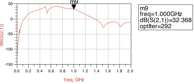
Simulation of transmission coefficient, S21 of RF2173 power amplifier was done. Since the input match for the driver is 50 Ω, hence the input matching is not required. In order to generate transmission coefficient simulation, the input matching termination of 50 Ω must be included. As the results, the transmission coefficient simulated results can be obtained from Figure 4 for power amplifier. The simulated results indicating, the transmission coefficient for the driver is performing 32.368 dB at 1000 MHz.
0.2 0.4 0.6 0.8 1.0 1.2 1.4 1.6 1.8
0.0 2.0
-100 -50 0
-150 50
freq, GHz
dB(S(2,1))
m9
m9 freq=
dB(S(2,1))=32.368 optIter=292
1.000GHz
Figure 4. Results of transmission coefficient for the driver amplifier.
5. RESULTS AND COMPARISON
shown in Figure 9 and Figure 10 respectively. Simulation results of open loop and close loop for 1000 MHz are shown in Figure 11 and Figure 12 respectively. The summary simulation performance of the
Envelope simulator I & Q demodulator
π/4 DQPSK source (generate I & Q signal)
I & Q modulator PA model with complete design
I & Q Demodulator PA model
with complete design
π/4 DQPSK source (generate I & Q
signal) Comparator
I & Q modulator
Figure 7. Open loop Cartesian feedback simulation results at 800 MHz.
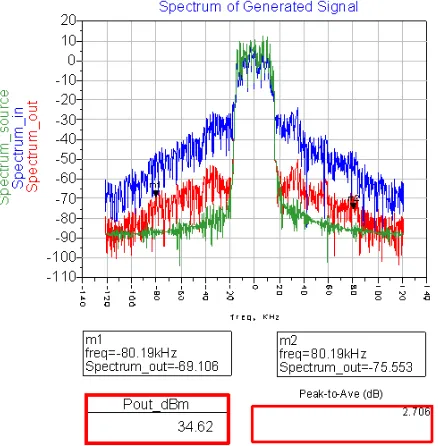
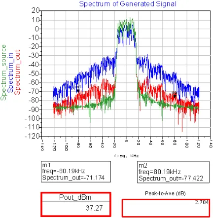
Figure 9. Open loop Cartesian feedback simulation results at 900 MHz.
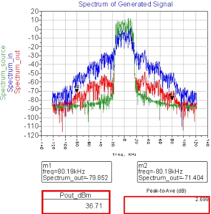
Figure 11. Open loop Cartesian feedback simulation results at 1000 MHz.
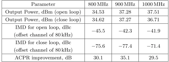
Cartesian feedback power amplifier is discussed further with aid of Table 1.
Table 1. Summary of open loop and close loop simulation result of Cartesian feedback power amplifier.
Parameter 800 MHz 900 MHz 1000 MHz Output Power, dBm (open loop) 34.53 37.28 37.51
Output Power, dBm (close loop) 34.62 37.27 36.71 IMD for open loop, dBc
(offset channel of 80 kHz) −45.5 −42.3 −41.9 IMD for close loop, dBc
(offset channel of 80 kHz) −75.6 −77.4 −71.4 ACPR improvement, dB 30.1 35.1 29.5
Based on the simulation results shown in Table 1, a good ACPR performance is achieved by implementing Cartesian feedback around 30 dB worst case at 1000 MHz. If a signal with varying envelope is applied to a power efficient non linear amplifier, the performance of a radio communications system will deteriorated. As result of the inter-modulation distortion generated in the amplifier, the spectrum of the signal will expand into adjacent channel causing interferences for other users. This phenomenon is illustrated in open loop Cartesian feedback simulation where the IMD is −45.5 dBc, −42.3 dBc and −41.9 dBc at 800 MHz, 900 MHz and 1000 MHz respectively. These spectrums will cause interference for other users and the distortion will make it more difficult for the receiver to correctly detect the information.
These inter-modulation distortions have a debilitating effect on the performance of power amplifier as well as the telecommunication systems. To avoid the interference due to the nonlinearity of the amplifier, close loop has been implemented. The inter-modulation distortion has been compressed to −75.6 dBc, −77.4 dBc and −71.4 dBc at 800 MHz, 900 MHz and 1000 MHz respectively. ACPR performance has been improved by 30 dB for worst case at 1000 MHz. This verifies that a linear power amplifier has been designed with the aid of Cartesian feedback. These close loop architecture reduced the occurrence of inter-modulation distortion which degrades the communication system’s performance. Hence, Cartesian feedback technique reduces the inter-modulation distortion by increasing the linearity of the power amplifier.
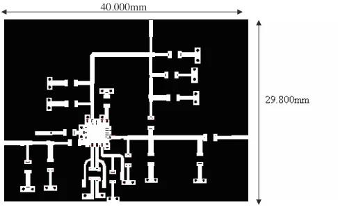
40.000mm
Figure 13. Layout of the RF2173 power amplifier design.
Layout artwork of the RF2173 power amplifier is done with the aid of Advanced Design System software. This final layout is prepared using Auto-Cad tools as shown in Figure 13. The ADS layout is unable to simulate because ADS momentum is an EM simulator. If we want to run a momentum simulation, we can’t use the artwork of the PA as momentum simulator is an EM simulator and can’t simulate the character of lumped parameter components.
6. CONCLUSION
REFERENCES
1. Albert, B. R., Introduction to Satellite Communications, 3rd edition, Artech House Inc., Norwood, MA, 2002.
2. Coskun, A. H. and S. Demir, “A mathematical characterization and analysis of a feedforward circuit for CDMA applications,” IEEE Transactions on Microwave Theory and Techniques, Vol. 51, 767–777, 2003.
3. Park, J. K., D. H. Shin, J. N. Lee, and H. J. Eom, “A full-wave analysis of a coaxial full-waveguide slot bridge using the fourier transform technique,” Journal of Electromagnetic Waves and Applications, Vol. 20, No. 2, 143–158, 2006.
4. Wu, C. and G.-X. Jiang, “Stabilization procedure for the time-domain integral equation,”Journal of Electromagnetic Waves and Applications, Vol. 21, No. 11, 1507–1512, 2007.
5. Dawson, J. and T. Lee, “Automatic phase alignment for high bandwidth Cartesian feedback power amplifiers,” IEEE Proceeding Radio and Wireless Conf., 71–74, 2000.
6. Makki, S. V., T. Z. Ershadi, and M. S. Abrishamian, “Determining the specific ground conductivity aided by the horizontal electric dipole antenna near the ground surface,” Progress In Electromagnetics Research B, Vol. 1, 43–65, 2008. 7. Mallahzadeh, A. R., A. A. Dastranj, and H. R. Hassani, “A
novel dual-polarized double-ridged horn antenna for wideband applications,” Progress In Electromagnetics Research B, Vol. 1, 67–80, 2008.
8. Mohammadi, F. A. and M. C. E. Yagoub, “Electromagnetic model for microwave components of integrated circuits,” Progress In Electromagnetics Research B, Vol. 1, 81–94, 2008.
9. Dawson, J. L. and T. H. Lee, “Automatic phase alignment for a fully integrated Cartesian feedback power amplifier system,”IEEE Journal of Solid-State Circuits, Vol. 38, 2269–2279, 2003.
10. Faulkner, M., D. Contos, and M. Briffa, “Performance of automatic phase adjustment using supply current minimization in a RF feedback lineariser,” Proc. 8th IEEE Int. Symp. Personal, Indoor, and Mobile Radio Communications, 858–862, 1997. 11. Khan, S. N., J. Hu, J. Xiong, and S. He, “Circular fractal
monopole antenna for low VSWR UWB applications,” Progress In Electromagnetics Research Letters, Vol. 1, 19–25, 2008.
13. Roy, N. and V. K. Devabhaktuni, “A new computer aided LNA design approach targeting constant noise-figure and maximum gain,”PIERS Online, Vol. 3, No. 8, 1321–1325, 2007.
14. Ma, H. and Q. Feng, “An improved design of feed-forward power amplifier,”PIERS Online, Vol. 3, No. 4, 363–367, 2007.
15. Huang, Q. and C. Menolfi, “A 200 nV offset 6:5 nV=pHz noise PSD 5.6 kHz chopper instrumentation amplifier in 1µm digital CMOS,” IEEE Int. Solid-State Circuits Conf. Dig. Tech. Papers, 362–363, 2001.
16. Sebak, S., L. Zhu, V. K. Devabhaktuni, and C. Wang, “A CRLH microstrip delay line for high-speed electronic circuits,” PIERS Online, Vol. 3, No. 3, 259–263, 2007.
17. Zhao, J., J. Zhou, N. Xie, J. Zhai, and L. Zhang, “Error analysis and compensation algorithm for digital predistortion systems,” PIERS Online, Vol. 2, No. 6, 702–705, 2006.
18. Huh, J. W., I. S. Chang, C. D. Kim, “Spectrum monitored adaptive feedforward linearization,”Microwave Journal, Vol. 44, 160–166, 2001.
19. Roy, N. and V. K. Devabhaktuni, “A new computer aided LNA design approach targeting constant noise-figure and maximum gain,” PIERS Proceedings in Prague, Prague, Czech Republic, August 27–30, 2007.
20. Presa, J., J. Legarda, H. Solar, J. Melendev, A. Munoz, and A. G. Alonso, “An adaptive feedforward amplifier for UMTS downlink transmitters,” 15th IEEE Int. Personal, Indoor and Mobile Radio Communications System, 2005.
21. Liao, S.-S., S.-Y. Yuan, H.-N. Lin, P.-T. Sun, and K.-C. Chuang, “Parallel-coupled microstrip filter using stepped-impedance and over-coupled end stages for suppression of spurious responses,” PIERS 2007 in Beijing Proceedings, Beijing, China, March 26–30, 2007.