Design and Optimization of a Dual-Band Sub-6 GHz Four Port
Mobile Terminal Antenna Performance in the Vicinity
of User’s Hand
Rizwan Khan1, Azremi Abdullah Al-Hadi1, *, Ping J. Soh1, Mohd T. Ali2, Samir S. Al-Bawri1, 3, and Owais4
Abstract—In this paper, the effects of the locations of four dual-band antennas on a mobile terminal chassis are investigated in the vicinity of user’s hand. To perform this study, a dual-band four-port mobile terminal antenna for 5G is designed for operation in between 3.34 and 3.84 GHz (lower band, LB) and 5.15 and 6.52 GHz (upper band, UB), respectively. Due to the symmetry of the antenna elements (AEs), a right hand standard phantom is placed at a fixed position. Meanwhile, the antenna elements are placed at seven different locations across the chassis, with the best possible locations chosen based on the maximum efficiency in data mode. The influence of the human hand on the antenna performance is assessed based on two aspects: 1) in terms of matching (impedance mismatch (IM) and impedance bandwidth (IB)); and 2) in terms of efficiency (radiation efficiency (RE) and total efficiency (TE)). To validate its performance, the proposed antenna has been fabricated and measured. Results showed good agreement between simulations and measurements. Based on the results, a general design guideline for future 5G antennas operating in the sub-6 GHz bands considering user’s hand effects can be outlined. The observed maximum variation for the proposed antenna with user’s hand in terms of IM is −8 dB and −5 dB, respectively, and 57% and 37% in TE, respectively.
1. INTRODUCTION
Wireless service providers are suffering from unprecedented limitations in availability of spectrum due to the increase of the use of smartphones and mobile data growth [1]. The carrier frequency spectrum for today’s wireless devices is limited, ranging between 700 MHz and 2.6 GHz [2]. Along with the standardization and implementation of the fourth generation (4G) cellular networks, research activities on future generation (5G) communication have emerged in both academia and industry [3]. Multiple input and multiple output (MIMO) and massive MIMO systems are the major components of 5G technology in achieving up to 100 times of bandwidth compared to 4G and Long Term Evaluation-advance (LTE-A) wireless systems. Implementation of smaller devices with improved features continuously complicates the design requirements for engineers. To overcome this issue, the promising solution is to increase the number of antennas which increases the data throughput by using MIMO technique with multi-antenna systems [4]. Multi-antenna terminals are widely available for providing high data rates to meet the demands of the rapidly growing MIMO system requirements [5]. Yet, the ever expanding bandwidth requirements for future mobile communication and the scarcity of antenna real estate in modern user terminals remain very challenging [6].
Received 1 May 2018, Accepted 9 June 2018, Scheduled 15 July 2018
* Corresponding author: Azremi Abdullah Al-Hadi ([email protected]).
Due to the ongoing 5G standardization activities at the moment, their operating frequency bands have not been formally issued. One of the realistic IMT bands announced during the World Radio Communication Conference 2015 (WRC-15) is the C-band between 3.4 and 3.6 GHz [7]. Therefore, investigation on the user’s effects in such sub-6 GHz bands is presently a topic of concern to many 5G researchers. The present 3.4 to 3.8 GHz band, which is the combination of LTE band 42 and LTE band 43, is now being widely investigated due to its potential in realizing 5G MIMO by researchers from China (3.4–3.6 GHz) [8], European Union (3.4–3.8 GHz) [9], and Korea (3.4–3.7 GHz) [10]. Besides that, another potential sub 6-GHz frequency band for 5G is LTE band 46 (5.1–5.925 GHz), also known as the unlicensed LTE band (LTE-U). Besides designing operational MIMO antennas in these sub-6 GHz bands, an additional step in ensuring operation in the design procedure is investigating the user on these mobile terminal antennas.
In realistic MIMO fading scenarios, a number of factors influencing performance have been investigated in [11], for instance, received signal to noise ratio (SNR), mutual coupling between antennas, the antenna array configuration, among others [12–15]. Terminal antennas are required to be robust in real usage, including its applications under user interactions [16]. Cellular telecommunication and internet association (CTIA), which is an international organization representative of the wireless industry, have specified the necessary dimensions of the hand phantom. They also have defined specifications concerning antennas designs with considerations of user’s body effect [17]. In particular, user effects need to be considered on the performance of MIMO systems as it detunes the operating frequency of the antennas. Besides that, power absorption which is caused by the proximity of the user’s hand varies depending on the antenna type, user hand and grip style [18]. This has also motivated hardware developers to request that these hand models are included in the future regulatory testing to guarantee over-the-air performance in practice [19]. For mobile terminals, the electrical characteristics of the antennas strongly depend on location where they are mounted on the chassis of the phone [20–23]. The understanding of the combined behavior of both the phone chassis and antenna element is the most vital part of the mobile terminal antenna design process. While the size and location of the antenna can be predetermined based on a volume [24], the variations of the locations of the user’s hands and their distances when the mobile terminal is being held during use are random and may affect its performance in a very different way. However, there is currently no available published effort in systematically characterizing the effects of the antenna-hand interaction based on the locations of terminal antenna in these new 5G frequency bands.
It is expected that the quantification of these interactions can be beneficial for antenna designers to consider and reduce the effect of users in the design process. In this paper, a systematic study on the sub-6 GHz 5G frequencies is performed using an extensive set of simulations to characterize the changes in IM, IB and efficiency due to the user’s hand, and quantify the trade-off with the antenna location on the chassis. To perform this study, a dual-band mobile terminal antenna with four ports operational in the sub-6 GHz bands for 5G is first designed. They are operational between 3.34 and 3.84 GHz, and from 5.15 to 6.52 GHz. The main trends of antenna interaction with user hand in terms of impedance mismatch (IM), impedance bandwidth (IB) and total efficiency (TE) in the presence of user’s hand are studied. Then, an average radiation efficiency and average matching efficiency is calculated for seven different antenna locations on its chassis. Finally, the optimal choice of antenna element (AE) location is made based on the maximum TE in the presence of user’s hand in data mode. To support these observations, the antenna is also fabricated and validated via measurements for comparison to simulation results.
This manuscript is organized as follows. First, the initial antenna structure and results in free space (FS) are presented, followed by the impact of the user’s hand on the antenna reflection and radiation characteristics. Next, the results and discussion of the optimal antenna location with different scenarios are presented. Finally, the concluding remarks to this work are presented in the last section of this paper.
2. ANTENNA STRUCTURE AND PERFORMANCE IN FREE SPACE (FS)
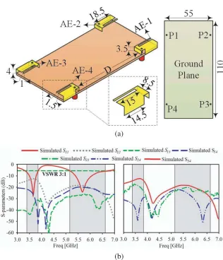
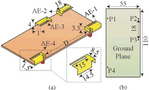
to these reasons, it is also chosen as the basis of this work. Figure 1(a) shows the design of the reference PIFA. Four symmetrical metallic AEs are placed at each corner of a rectangular Rogers RT/Duroid-5880 substrate with a thickness of 1.575 mm and permittivity of 2.2. The total volume of each AE is 18.5×8.5×4 mm3, whereas the metallic conductor is 0.291 mm thick. A slot is optimized across each AE to achieve dual-band operation, whereas further dual-band impedance tuning is performed using a 14.5 mm shorting plate attached on one side of the antenna. In addition to that, a small 3.5 mm bend from the length of the antenna is also used for frequency tuning, beside the feeding point. Firstly, the S-parameters in free space (FS) are extracted and shown in Figure 1(b). Due to the symmetrical location of the AEs, i.e., S11 = S22 =S33 =S44, only S11 for reflection and for mutual coupling S12,
S13, S14,S23,S24, and S34 are shown in Figure 1(b).
(a)
(b)
Figure 1. (a) Reference antenna design (all dimensions in millimeters), and (b) reference antenna
S-parameters in FS.
3. IMPACT OF THE USER’S HAND ON ANTENNA REFLECTION AND RADIATION CHARACTERISTICS
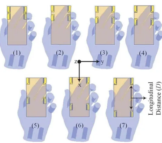
Figure 2. Seven different antenna placements on the chassis.
implementation of more than one antenna enables the use of an alternate antenna in the case that the user significantly affects one of them. For full wave simulations, the time domain solver in CST Microwave studio is used to model the interaction between the proposed antenna and SHO3TO6-V3 right hand phantom [25] (εr= 22.5 at 3–6 GHz) with seven different placements of AEs (see Figure 2). This hand phantom exhibits a real human hand and is compliant with CTIA test plan for wireless device over-the-air performance. The antenna is confined in a 1.5 mm thick casing dimensioned at 112×57×7.7 mm3, with a relative permittivity of 2.8. This is to provide a standardized comparison using the worst case interaction, so that a minimal separation to the user is achieved prior to the analyses of IM, IB and TE.
3.1. Effect of the Hand Phantom on the Antenna’s Operation
The presence of the user in the antenna near-field region is expected to change the antenna’s impedance matching and consequently its bandwidth due to the dielectric loading introduced by the tissue. Thus, the different AE locations on the chassis are assessed in terms of IM and IB which are performed using the center frequencies in the lower and upper bands.
Seven different locations are chosen based on the separation distance, D, and this parameter is expressed in terms of free space wavelength (λ) while observing the antenna performance. These values ofλare calculated based on the center frequencies of LB and UB, i.e., λ= 85.7 mm (at 3.58 GHz), and
λ= 51.8 mm (at 5.79 GHz), respectively.
This parameter is initially determined along the longitudinal axis of the chassis in five 18.5 mm intervals based on the size of the antenna element. This interval translates into D= 0.20λ in the LB and D= 0.23λ in the UB. Next, once the antennas are placed closely enough to each other (based on the changes in total efficiency to simulate the worst case scenario), a more refined 6 mm interval is used to sweep the antenna locations. This is performed for further two separations up toD= 0λin both LB and UB.
(a)
(b)
Figure 3. Bandwidth and matching level of the proposed antenna when held in user’s hand in (a) LB and (b) UB.
Similarly, in the upper band, a maximum IM of −5 dB is observed for D = 1.06λ, whereas a 390 MHz of maximum shift in resonance is noticed at D = 0.11λ, as seen in Figure 3. It is obvious that the maximum value of matching is observed without the user’s hand, and this value is used as the reference level of antenna matching.
3.2. Effects of the Hand Phantom on the Antenna’s Radiation Characteristic
The degradation of the antenna performance due to the proximity of the user’s hand is evaluated in terms of TE reduction in this section. First, the antenna TE is calculated when the antenna is placed inside the casing, prior to its assessment for the seven different antenna locations on the mobile terminal chassis. Finally, the antenna average radiation efficiency and average matching efficiency are calculated prior to the TE measurements.
3.2.1. Effects of the Casing on Total Efficiency
Figure 4. Measured and simulated TE of the proposed antenna in free space and with casing.
3.2.2. Effects of the Hand Phantom on Total Efficiency
Another important factor which decreases the antenna efficiency is the absorption of the electromagnetic waves by the human tissue. Besides the performance degradation, such electromagnetic energy absorption by the biological tissues also possesses a potential health risk. Moreover, the full wave EM simulator will not be able to accurately account for material and mismatch losses [8]. This is because when an antenna is placed in the vicinity of or on a lossy medium, its conventional pattern properties cannot be used to derive efficiency due to the medium losses. This is because of medium losses which cause the wave in the far-field region to attenuate more rapidly and finally to zero.
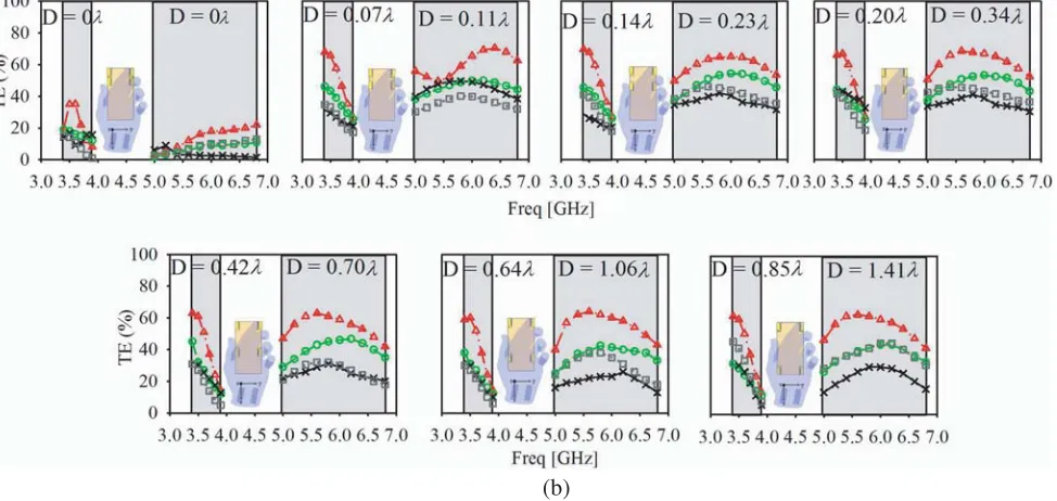
To examine the behavior of efficiency, the characteristics of the AUT are studied using casing and the standard CTIA hand phantom. The effects of the location changes of the antenna on the TE can be observed in Figure 5. Initially, a high TE in the FS scenario is seen in Figure 5(a), as expected, due to the absence of the user’s hand. Meanwhile, the presence of this hand then deforms the antenna far-field radiation pattern, as seen Figure 5(b). From this figure, it is also observed that TE is most affected when a thick human hand phantom is placed closer to the AE. The most affected antenna in terms of TE is AE-3. Besides the thicker human hand which absorbs more power, the thickness also
(b)
Figure 5. Total efficiency for different locations of the antenna elements: (a) without user’s hand; and (b) with user’s hand.
results in a much closer location of AE-3 with the hand phantom than other antenna placements in data mode. When the location of AE-3 is moved further away from this hand (from 0.85λto 0.11λ in the LB and from 1.41λto 0.11λ in UB), TE starts to gradually increase as shown in Figure 5(b). The maximum TE for AE-3 is observed when the separation is at 0.14λ in LB and 0.23λin UB. Note that when D = 0.11λ, some discontinuity in TE is observed in UB, possibly caused by the higher mutual coupling between AE-2 and AE-3. The worst case scenario observed in terms of TE is when λ is less than 0.07 for LB and 0.11 for HB, as can be observed in the sudden degradation of TE for all AEs.
3.2.3. Average Radiation Efficiency and Average Matching Efficiency
From the TE, the values for radiation efficiency (RE) and matching efficiency (ME) can be further calculated. Simulations show that both matching and radiation efficiency are significantly affected with the different antenna locations on the chassis. Figure 6 shows the simulated average RE as a function of antenna separation on the chassis for seven different locations in the LB (from 3.34 to 3.84 GHz) and
(a) (b)
UB (from 5.15 to 6.52 GHz). It is shown in the Figure 6 that the RE of AE-2 remains constantly high for all locations, due to the absence of interaction between this AE and the user’s hand. Meanwhile, the efficiency for AE-1 also shows constant value for all locations due to the consistency of the finger position holding the terminal throughout all simulations. On the contrary, a large change in efficiency is seen with a larger hand thickness around AE-3.
Figure 6 also indicates that the increase of the longitudinal distance between the AEs decreases the efficiency of AE-3. This is due to a much closer distance of AE-3 to the thicker human hand tissues in both LB and UB. On the other hand, the maximum radiation efficiency for AE-4 is found atD= 0.85λ and 1.41λin LB and UB, respectively. Similarly, the average ME is calculated in Figure 7 for both LB and UB.
(a) (b)
Figure 7. Average matching efficiency, (a) lower band; and (b) upper band.
4. VALIDATION OF SIMULATED RESULTS
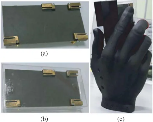
Upon completion of the analysis of the location of AE-3 and AE-4 of the reference antenna using the user’s right hand, the optimized AE location on the mobile terminal chassis with best performance is determined and shown in Figure 8. The proposed AUT is then fabricated, as shown in Figure 9 and integrated with a casing for assessment when being held in a user’s right hand. TheS-parameters are first measured and compared with simulation in FS, as shown in Figure 10, indicating a good agreement between them. It can be seen that the measured impedance bandwidth in LB is 0.5 GHz (from 3.34 to 3.84 GHz), and the bandwidth obtained in UB is 1.37 GHz (from 5.15 to 6.52 GHz). This indicates
(a) (b)
(a)
(b) (c)
Figure 9. Fabricated prototype of the proposed antenna when assessed in: (a) free space, (b) with casing, (c) with casing and user’s hand.
(a) (b) (c)
Figure 10. Simulated and measured results, (a)S11, (b)S12,S13,S14 and (c)S23,S24,S34.
Table 1. Maximum isolation of the four-port mobile terminal antenna.
Isolation (dB) Lower Band Upper Band
S12 −13.0 −19.0
S13 −18.0 −19.0
S14 −36.0 −22.6
S23 −31.0 −19.0
S24 −30.0 −25.0
S34 −28.0 −27.0
its suitability for sub-6 GHz 5G applications based on a S11 limit of less than −6 dB. The maximum isolations at these center frequencies are summarized in Table 1.
the symmetry of the AEs. The measured S-parameters of the proposed antenna with the casing is shown in Figure 11(a). A good agreement is found between simulated and measured results, with slight differences possibly caused by imperfect SMA connector assembly. Based on the measured results the AUT with casing operates from 3.24 to 3.76 GHz (in LB) and from 5.02 to 6.48 GHz (in UB). Shifts of 100 MHz and 130 MHz are observed in LB and UB due to the effects of the dielectric casing’s proximity to the AEs. Meanwhile, Figure 11(b) shows the measured S-parameters of the proposed antenna in the casing when being held using the hand phantom. An additional shift of 60 MHz towards the lower frequency along with the impedance mismatch about 16 dB is observed in the LB. Meanwhile, in UB, a bandwidth increase around 290 MHz is observed, with a degradation of the impedance matching level from −25 dB to −12 dB. These values indicate the additional level of impedance mismatch and shift
(a)
(b)
Figure 11. Simulated and measuredS-parameters: (a) with casing, (b) with user’s hand.
in resonant frequency due to dielectric loading of the user’s hand on the mobile terminal. Note that in Figure 11(a), only the reflection coefficient (S11) and isolations (S12, S13, S14, S23, S24 and S34) from selected ports are shown due to the symmetry of the design. However, for the assessment with user’s hand (Figure 11(b)), allS-parameters are illustrated due to the difference in AE behavior in the presence of the user’s hand. The operating regions of the proposed antenna in free space are shaded in Figures 11(a) and (b) to facilitate the assessment in terms of resonant frequency shift in proximity of the casing and hand.
(a) (b)
Figure 13. Simulated and measured total efficiency, (a) for AE-1, and AE- 2; and (b) for AE-3 and AE-4.
5. CONCLUSION
This paper investigates the effects of the user’s hand on the impedance matching, bandwidth and efficiency of a dual-band, four-port mobile terminal antenna for sub-6 GHz 5G applications. These impacts have been studied within the antenna operation from 3.34 to 3.84 GHz (in the lower band) and from 5.15 to 6.52 GHz (in the upper band) relative to its performance inside a casing and in free space. These simulations, which are validated experimentally, are also in good agreement with each other. From the detailed trends of the impedance matching, bandwidth and efficiency gathered from this investigation, it can be concluded that the best antenna performance depends on the location of its elements on the mobile terminal chassis with respect to the user’s hand, besides the operating frequency. This is mainly due to the effects of the dielectric loading and power absorption by the user’s hand when holding the mobile terminal, which affects its near-field behavior. The presented study provides useful insights for engineers in designing antennas with multiple elements while simultaneously accounting for the effects of the user’s hand. Moreover, the use of a planar inverted-F antenna, which is a popularly used topology for mobile terminals, is expected to facilitate the design process for future 5G mobile terminals.
ACKNOWLEDGMENT
This research was supported financially by the Ministry of Science, Technology and Innovation under eScience fund (Grant No.: 01-01-015-SF0258).
REFERENCES
2. Rappaport, T. S., S. Sun, R. Mayzus, H. Zhao, Y. Azar, K. Wang, G. N. Wong, J. K. Schulz, M. Samimi, and F. Gutierrez, “Millimeter wave mobile communications for 5G cellular: It will work!,”IEEE Access, Vol. 1, 335–349, 2013.
3. Chih-Lin, I., C. Rowell, S. Han, Z. Xu, G. Li, and Z. Pan, “Toward green and soft: A 5G perspective,”IEEE Communications Magazine, Vol. 52, No. 2, 66–73, 2014.
4. Foschini, G. J. and M. J. Gans, “On limits of wireless communications in a fading environment when using multiple antennas,”Wireless Personal Communications, Vol. 6, No. 3, 311–335, 1998. 5. Lau, B. K., “Multiple antenna terminals,”MIMO: From Theory to Implementation, 267–298, 2011. 6. Al-Hadi, A. A. and R. Tian, “Impact of multiantenna real estate on diversity and MIMO performance in mobile terminals,” IEEE Antennas and Wireless Propagation Letters, Vol. 12, 1712–1715, 2013.
7. WRC-15 Press Release, “World radio communication conference allocates spectrum for future innovation,” [online], available: http://www.itu.int/net/pressoffice/pressreleases/2015/56, Nov. 27, 2015
8. MT-2020 (5G) Promotion Group, “White paper on 5G concept,” [online], available: http://www.-imt-2020.org.cn/zh/documents/download/4, Feb. 2015.
9. Qualcomm, “Making the best use of licensed and unlicensed spectrum,” [online], available: https: //www.qualcomm.com/media/documents/files/making-the-best-useof-unlicensed-spectrum-presentation.pdf, Sep. 2015.
10. SK Telecom, “SK telecom 5G white paper,” [online], available: http://www.sktelecom.com-/img/pds/press/SKT5G%20White%20PaperV1.0 Eng.pdf, Oct. 2014.
11. Ali, S. M., A. Mobasher, and P. Lusina, “User presence and antenna efficiency effects on MIMO link performance,”72nd Vehicular Technology Conference Fall (VTC 2010-Fall), 1–5, IEEE, 2010. 12. Goldsmith, A., S. A. Jafar, N. Jindal, and S. Vishwanath, “Capacity limits of MIMO channels,”
IEEE Journal on Selected Areas in Communications, Vol. 21, No. 5, 684–702, 2003.
13. Skafidas, E. and R. J. Evans, “Antenna effects on the capacity of MIMO communications systems in Rayleigh channels,”15th IEEE International Symposium on Personal, Indoor and Mobile Radio Communications, PIMRC, Vol. 1, 617–621, IEEE, 2004.
14. Piazza, D., N. J. Kirsch, A. Forenza, R. W. Heath, and K. R. Dandekar, “Design and evaluation of a reconfigurable antenna array for MIMO systems,” IEEE Transactions on Antennas and Propagation, Vol. 56, No. 3, 869–881, 2008.
15. Kildal, P. S. and K. Rosengren. “Correlation and capacity of MIMO systems and mutual coupling, radiation efficiency, and diversity gain of their antennas: Simulations and measurements in a reverberation chamber,”IEEE Communications Magazine, Vol. 42, No. 12, 104–112, 2004.
16. Vasilev, I. and B. K. Lau, “On user effects in MIMO handset antennas designed using characteristic modes,”IEEE Antennas and Wireless Propagation Letters, Vol. 15, 758–761, 2016.
17. Ying, Z., “Antennas in cellular phones for mobile communications,” Proceedings of the IEEE, Vol. 100, No. 7, 2286–2296, 2012.
18. Buskgaard, E., A. Tatomirescu, S. C. Del Barrio, O. Franek, and F. F. Pedersen, “User effect on the MIMO performance of a dual antenna LTE handset,” 8th European Conference on Antennas and Propagation (EuCAP), 2006–2009, IEEE, 2014.
19. Li, C. H., E. Ofli, N. Chavannes, and N. Kuster, “Effects of hand phantom on mobile phone antenna performance,”IEEE Transactions on Antennas and Propagation, Vol. 57, No. 9, 2763–2770, 2009. 20. Taga, T. and K. Tsunekawa, “Performance analysis of a built-in planar inverted F antenna for 800 MHz band portable radio units,”IEEE Journal on Selected Areas in Communications, Vol. 5, No. 5, 921–929, 1987.
22. Taga, T., “Analysis of planar inverted-F antennas and antenna design for portable radio equipment,” Analysis, Design, and Measurement of Small and Low Profile Antennas, 161–180, 1992.
23. Vainikainen, P., J. Ollikainen, O. Kivekas, and K. Kelander, “Resonator-based analysis of the combination of mobile handset antenna and chassis,” IEEE Transactions on Antennas and Propagation, Vol. 50, No. 10, 1433–1444, 2002.
24. Ilvonen, J., O. Kivekas, J. Holopainen, R. Valkonen, K. Rasilainen, and P. Vainikainen, “Mobile terminal antenna performance with the user’s hand: Effect of antenna dimensioning and location,” IEEE Antennas and Wireless Propagation Letters, Vol. 10, 772–775, 2011.