Design a High Quality Grid Connected PV Systems with Constant
Power Generation and Input Output Linearizer Controller
Kisan Kumar
1, Bibha Rani Singh
2, Anjana Tripathi
31
PG Scholar,
2Assistant Professor,
3Assistant Professor
1, 2, 3
Dept. of Electrical Engineering,
Rabindranath Tagore University, Bhopal (M.P)
Abstract -
With Increase in demand of clean electricity generation in many countries, the increasing techniques of new photovoltaic (PV) systems force the Distribution System for transmission and distribution of electricity. By considering this aspect, the distributors of electricity are focused to ensure fast and smooth transformation between maximum power point tracking and constant power generation so the maximum feeding power of PV systems must be limited. Optimum performance and stable operations are achieved in spite of solar irradiance levels by the new control technique which is proposed. In this strategy, PV output power can be regulated as per desired set point and force to operate the PV system at left side of maximum power point without any stability issues. This system consists of solar PV panel, boost converter, MPPT controller, inverter, LCL filter and Load. Here, PV system as energy source. The power generated from solar photovoltaic system is controlled by DC-DC boost converter. A modelling of this system is developed in MATLAB/Simulink. Constant power generation (CPG) control is much effective strategy in terms of stable transitions, high accuracy and fast dynamics which have been verified by experimental results.Key Words: Active power control, constant power control, maximum power point tracking, PV systems, and power converters
1. INTRODUCTION
As the conventional energy sources produces air pollution, water pollution solid pollution, so this is very harmful to human beings. Hence the non-conventional energy sources like Solar PV panels and wind turbines are generally used. In general photovoltaic panels are used today in rural areas where the grid connected system is not convenient. Also photovoltaic panels are used in various applications such as water pumps, residential applications and many more. The photovoltaic system has many advantages as It is available freely in nature, no pollution but their installation cost is more due to the use of power convertors like dc to dc or dc to ac, storage batteries and this system have low conversion efficiency hence to increase conversion efficiency various MPPT techniques can be used to compare the PV array voltage or current under specific atmospheric conditions [1]. Modelling of the Solar Cell.
Solar photovoltaic is a system to convert light energy into electrical energy. The solar photovoltaic system produces easy and clean energy. The solar systems can be installed on a house or big industry. The solar panels use the solar irradiance to generate electrical energy. The simple equivalent circuit of a solar cell is a photocurrent as a current source in parallel with a diode. The output of the photovoltaic panel depends on the light
falling on the cell. The circuit diagram shows the I-V characteristics of the Photovoltaic cell [2].
Fig. 1(a) Equivalent circuit of photovoltaic cell
The current flowing through the diode is
Where:
I
Lis the load current (A)
I
phis the photocurrent (A) I0 is the diode current q is the
charge of electron = 1.6x10 −19 coulomb.
K is the Boltzmann constant (j/K)
T is the temperature of cell (K)
R
sand Rsh are the series and shunt resistors of the cell,
respectively
Fig. 1 (B). Hardware schematic and overall control structure of a two-stage singlephase grid-connected PV system.
Fig. 2: I-V characteristic of a solar panel
The product of voltage and current characteristic shows
power and we obtain the P-V characteristics of
photovoltaic panel as shown in figure 3.
Fig. 3: P-V characteristic of a photovoltaic panel
II. COMMONLY USED MPPT TECHNIQUES
Constant Voltage Method
This method is the easiest method to achieve MPP. This method measures the photovoltaic panel voltage by using PI controller to adjust the duty cycle of the dc to dc converter in order to maintain the PV voltage near the MPP. The output voltage is regulated to a constant value under all conditions and one in which the output voltage is regulated based on a constant ratio to the measured open circuit voltage (VOC). [3]
A. Open Circuit Voltage Method
In this method the voltage of PV cell at maximum power point (Vmpp) is linearly proportional to the open circuit voltage Voc. This Vmpp can be calculated as
Vmpp = K1 Voc
The value of K has always between 0.7 to 0.8 Voc is updated as per the time for compensation of any temperature change.
Once the value of K1 is known the maximum power point voltage (Vmpp) can be determined by measuring Voc But when we measure VOC the power converter has to be shut down for short time so more power loss will occurs. Another disadvantage
of this method is that it is unable to track the maximum power point and one more disadvantage is that the MPP reached is only an approximation. [4][5].
B. Short Circuit Current Method
This method explains the relationship between photovoltaic current (Iph) to the corresponding maximum power current and short circuit current Isc. And determines the current factor K by using the relation. Imp=KIsc The value of K lies between 0.8 to 0.9
C. Incremental conductance method
The Incremental conductance method determines the MPP without disturbing the operating point. If this condition is not achieve the MPPT operating point must be perturbed can be calculated using the relation between dl/dV and –I/V.
At MPP the slope of PV curve is zero.
The above equation represents the conductance of the solar PV panel at any instant. When this conductance equal to the conductance of solar cell then Mpp is reached. Here we are getting both the voltage and current simultaneously. Hence the error due to change in irradiance is reduced. the disadvantage of this method is that complexity increases as well as and the cost of implementation is unaffordable. So this method is used for highly complicated systems. Hence the perturb and observe methods are most widely used. [3]
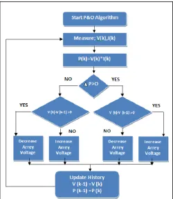
D. Perturb and observe Method
This is simplest method of MPPT. In this method we use voltage sensor to sense the PV voltage. So its implementation cost is low. The algorithm of this method is very simple but it reaches very close to the MPP. But not at MPP. and keeps disturbing on both the direction. this algorithm has reached very close to the Mpp. and we can set an appropriate error limit. This is called as P&O method. It is mostly used due to its reliability.
1) Advantages:
P&O is most commonly used in practice because 1) Its algorithm is simple.
2) Easy to implementation.
3) It has better accuracy than others methods.
E. Drawbacks:
1. This algorithm cannot determine the actual MPP. The output power always oscillates around the MPP but cannot reach at Mpp. This oscillation problem can be decreased by using various minimization techniques. [3]
Fig. 4: Algorithm of P & O Method
III. BLOCK DIAGRAM OF PROPOSED
SYSTEM
Fig. 5: Block diagram of a two-stage single phase grid-connected PV system.
A. Boost converter
PV module is connected to output resistive load through DC-DC boost converter. For switching in boost converter MOSFET is used. The duty ratio of boost converter is controlled by pulse generated via MPPT technique. These pulses are generated by comparing a carrier wave to control signal. Elements, inductor (L) and capacitor (C), values are selected through following equations provides very high impedance at fundamental frequency hence draws negligible current.
Fig. 6: DC-DC boost converter
IV. DESIGN AND DEVELOPMENT OF
TWO-STAGE SINGLE PHASE GRID-CONNECTED
PV SYSTEM
Fig. 7: Simulation model of two-stage single phase grid-connected PV system.
The PV Array block implements an array of photovoltaic (PV) modules. The array is built of strings of modules connected in parallel, each string consisting of modules connected in series. The PV Array block has two inputs that allow you to supply varying sun irradiance (input Ir in W /m^2) and temperature (input T in deg. C) data. The PV Array consists of one string of 40 BP SOLAR BP365TS 10 modules connected in series. At 25 deg. C and with a solar irradiance of 1000 W/m2, the string can produce 1500 W. PV array output Voltage is 110V.
V. SIMULATION RESULTS & DISCUSSION
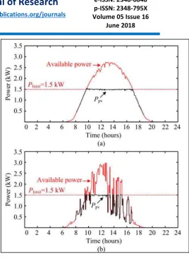
Fig. 8 (a & b) shows the performance of the conventional P&O-CPG method and Fig. 9 (a & b) shows the proposed high performance P&O-CPG method with two daily conditions. The overshoots and power losses are significantly reduced by the proposed solution and a stable operation is also maintained. The algorithm also has a selective behavior to only react, when the fast irradiance condition is detected.
Fig. 8: Results of the P&O-CPG algorithm under two daily conditions: (a) clear day and (b) cloudy day.
C. Experimental Verification
Solutions to improve the dynamic performance of the P&OCPG algorithm have been discussed previously. Parameters of the proposed high-performance P&O-CPG algorithm are designed as: γ = 10, k = 0.715, εinc = 50 W, εdec = 100 W, and εss = 30 W. Experiments are carried out referring to Fig. 1(B), and the system parameters are given in Table I. In the experiments, a 3-kW PV simulator has been adopted, where real-field solar irradiance and ambient temperature profiles are programmed.
Fig. 9: Results of the proposed high-performance P&O-CPG algorithm under two daily conditions: (c) clear day and (d) cloudy
day.
VI. CONCLUSION
A high-performance active power control scheme by limiting the maximum feeding power of PV systems has been proposed in this paper. The proposed solution can ensure a stable constant power generation operation. Compared to the traditional methods, the proposed control strategy forces the PV systems to operate at the left side of the maximum power point, and thus it can achieve a stable operation as well as smooth transitions. Experiments have verified the effectiveness of the proposed control solution in terms of reduced over-shoots, minimized power losses, and fast dynamics. Notably, for single-stage PV systems, the same CPG concept is also applicable. However, in that case, the PV voltage operating range is limited and minor changes in the algorithms are necessary to ensure a stable operation.
APPENDIX
Parameters Specification
PV Panel 3 KW, 110 V, 3.73 A
Boost converter
inductor L = 1.8 mH
PV-side capacitor Cpv = 1000 μF
LCL-filter L inv = 4.8 mH, Lg = 4 mH, Cf = 4.3 μF
Switching frequency Boost converter f b = 16 kHz
Full-Bridge inverter finv=8 kHz
DC-link voltage Vdc = 450 V
Grid nominal voltage
(RMS) V g = 230 V
Grid nominal frequency ω0 = 2 π×50 rad/s
Table 1: Simulation Parameters
REFERENCES
[1] Y. Yang, H. Wang, F. Blaabjerg, and T. Kerekes, “A hybrid power control concept for PV inverters with reduced thermal loading,” IEEE Trans. Power Electron., vol. 29, no. 12, pp. 6271–6275, Dec. 2014.
[2] A. Ahmed, L. Ran, S. Moon, and J.-H. Park, “A fast PV
power tracking control algorithm with reduced power mode,” IEEE Trans. Energy Conversion, vol. 28, no. 3, pp. 565–575, Sept. 2013.
[3] Y. Yang, F. Blaabjerg, and H. Wang, “Constant power generation of photovoltaic systems considering the distributed grid capacity,” in Proc. of APEC, pp. 379–385, Mar. 2014.
[4] R. G. Wandhare and V. Agarwal, “Precise active and reactive power control of the PV-DGS integrated with weak grid to increase PV penetration,” in Proc. of PVSC, pp. 3150–3155, Jun. 2014.
[5] W. Cao, Y. Ma, J. Wang, L. Yang, J. Wang, F. Wang, and
L. M. Tolbert, “Two-stage PV inverter system emulator in converter based power grid emulation system,” in Proc. of ECCE, pp. 4518–4525, Sept. 2013.
[6] A. Urtasun, P. Sanchis, and L. Marroyo, “Limiting the power generated by a photovoltaic system,” in Proc. of SSD, pp. 1–6, Mar. 2013.
[7] S. B. Kjaer, J. K. Pedersen, and F. Blaabjerg, “A review of single-phase grid-connected inverters for photovoltaic modules,” IEEE Trans. Ind. Appl., vol. 41, no. 5, pp. 1292– 1306, Sept. 2005.
[8] F. Blaabjerg, R. Teodorescu, M. Liserre, and A. V. Timbus, “Overview of control and grid synchronization for distributed power generation systems,” IEEE Trans. Ind. Electron., vol. 53, no. 5, pp. 1398–1409, Oct. 2006.
[9] A.Thenkani, ’ Dr.N.Senthil Kumar,”Design of Optimum
Maximum Power Point Tracking Algorithm For Solar
Panel” International Conference on Computer,
Communication and Electrical Technology – ICCCET 2011, 18th & 19th March, 2011.
[10] Reza Reisi, Ali, Mohammad Hassan Moradi, and Shahriar
Jamasb. "Classification and comparison of maximum power point tracking techniques for photovoltaic system: A review", Renewable and Sustainable Energy Reviews, 2013.
[11] EI SHWE ZIN PHYO1, KYAW SOE LWIN2, HLA MYO
TUN3 “Microcontroller Based Solar Smart Charge Controller using MPPT” ISSN 2319-8885 Vol.03,Issue.06, May-2014, Pages:0997-1000.
[12] Adel A. Elbaset1, Ahmed Emad-Eldin Hussein2, Ayman
Brisha2, Ramadan Mahmoud Mostafa2 “Implementation of
a PIC-based, Photovoltaic Maximum Power Point Tracking Control System” International Journal of Emerging
Technology and Advanced Engineering Website:
www.ijetae.com (ISSN 2250-2459, ISO 9001:2008Certified Journal, Volume 4, Issue 5, May 2014).
[13] A. Mamun1, M. F. Elahi2, M. Quamruzzaman3, M. U. Tomal4 Design and Implementation of Single Phase Inverter International Journal of Emerging Technology and Advanced Engineering Website: www.ijetae.com (ISSN 2250-2459, Volume 2, Issue 1, February 2012).
[14] Bijoyprakash Majhi “Analysis of Single-Phase SPWM
Inverter” A Thesis Submitted In Partial Fulfillment Of The Requirements Forthe Degree Of Bachelor Of Technology In Electrical Engineering National Institute of Technology, Rourkela May 2012.
[15] Nishit Kapadia, Amit Patel, Dinesh Kapadia “Simulation
and design of low cost single phase solar inverter”. [16] Gaurav Arora, Neha Aggarwal, Debojyoti Sen, Prajjwal
Singh “Design Of Solar Power Inverter” National conference on Renewable Energy and Environment (NCREE-2015) IMS Engineering College, Ghaziabad Vol. 2, Special Issue 1, May 2015.