119 | P a g e
THE ANALYSIS AND DESIGN OF G+40 STOREY
REGULAR STRUCTURE WITH DIFFERENT SHEAR
WALLS FOR LOOSE SOILS
K Crown Mojes
1, B. Ajitha
2 1PG Student in Computer Aided Structural Engineering, JNTUCEA, Anantapur (India)
2AssistantProfessor, Department of Civil Engineering, JNT University, Anantapur (India)
ABSTRACT
Shear walls are structural members used to augment the strength of RCC structures. These shear walls will be
built in each level of the structure, to form an effective box structure. Equal length shear walls are placed
symmetrically on opposite sides of exterior walls of the building.
The present work deals with a study on the optimum location of different shapes of shear walls in symmetrical
high rise building. Position of shear walls in symmetrical buildings has due considerations. In symmetrical
buildings, the center of mass and center of rigidity coincide, so that the shear walls are placed symmetrically
over the outer edges or inner edges (like box shape). It is very necessary to determine efficient and ideal
location of shear walls in symmetrical buildings to minimize the torsion effect. In this work a high rise building
with different locations of shear walls and different shapes of shear walls is considered for analysis. The high
rise building with 40 storeys is analyzed for its displacement, torsion, strength and stability using ETABS
software. For the analysis of the building for seismic loading Zone 2 Zone 3 Zone 4 & Zone 5 is considered with
soil type 1. The analysis of the building is done by using equivalent static method and response spectrum
method. The results from the analysis obtained from both the methods are presented in tabular form and the
results are compared using graphical form.
The results of the analysis on the shear force, bending moment and torsion are compared. Zone wise results are
also compared. The results are presented in tabular and graphical form. The results on the drift and
displacement are checked with serviceability conditions and are compared and presented in tabular form.
I . INTRODUCTION
Adequate stiffness is to be ensured in high rise buildings for resistance to lateral loads induced by wind or
seismic events. Reinforced concrete shear walls are designed for buildings located in seismic areas, because of
their high bearing capacity, high ductility and rigidity. In high rise buildings, beam and column sizes work out
large and reinforcement at the beam-column junctions are quite heavy, so that, there is a lot of clogging at these
joints and it is difficult to place and vibrate concrete at these places which does not contribute to the safety of
120 | P a g e
masonry continuous vertical walls may serve both architecturally as partitions and structurally to carry gravity
and lateral loading. There will be no architectural difficulty in extending them through the height of the
building;their very high in plane stiffness and strength had proved them to be ideally suited for resisting lateral
loads. Compared to frame type structures, shear-wall structures offer less distortion and less damage to
nonstructural elements. Care shall be taken to have symmetrical configuration of walls in the building so that
torsion effect in plan could be avoided.
In a shear wall structure, shear walls are entirely responsible for the lateral load resistance of the building due to
seismic and wind loadings. These shear walls act as vertical cantilevers in the form of separate planar walls, and
also as non planar assemblies of connected walls around stair case, elevators and service shafts
II. LITERATURE REVIEW
2.1 Rosinblueth and Holtz “Analysis of shear walls in tall buildings” (1960)
considered completelyuniform structure suggested a solution of a differential equation and presented tables which are useful for
symmetric buildings. The method requires assumption of first approximation which is improved in successive
iterations which describes shear wall with entire load if it is much more rigid than the rest of structure and if it is
not then the initial distribution of horizontal shear among walls and frames may differ widely. Therefore more
121 | P a g e
2.2 Clough.R, King I.P
and
Wilson E.I-“Structural analysis of multi storied buildings” (1964)
had given presentation on efficient digital method for structural analysis of large multi stored building frames
with arbitrary system of shear wall. Loading on the structure can be both vertical and lateral but except torsion,
they assumed (1) floor diaphragms are rigid in own plane (2) Axial deformations of beams are neglected and for
columns and shear walls are considered.
2.3Khan, F.R. and Sbrounis, J.A,
(7)„Introductionof shear wall with frames in
concreteSabrcounisstructure under lateral loads‟ (1964)
had considered shear wall and frame as twoseparate analytical components and done analysis by iterative method to satisfy equilibrium and compatibility
conditions at the points of connection of wall and frame . Initially entire lateral load is carried by the individual
shear wall and the corresponding deflection at each floor are determined, next the shear wall is individually
forced to the deflected shape of the first shear wall shear wall, negative shear wall individual shear walls are
computed these are applied to first wall and so on
2.4 Girijavallabhan
(2)- “Analysis of shear walls” (1969
)
found that finite element method is moreadvantageous than the finite difference method. The method mainly focus on structural continuum to be
analyzed into small finite elements interconnected to specific nodal points. This method of finite element
produces same properties done in the continuum.
2.5 Paulay,T.,
and
Priestley , "Seismic design of reinforced concrete and masonry buildings"
(1992).
Presented most reinforced concrete buildings with shear walls have columns. These columns primarilycarry gravity loads. Shear walls provide high strength and stiffness to the structure in the direction of its
orientation focusing in significantly helps in reducing lateral sway of the building and thereby reduces damage
to the structure and its contents.
III. METHODOLOGY
3.1 Geometrical Properties
[1] Height of typical storey = 2.7 m
[2] Height of ground storey = 3.2 m
[3] Length of the building = 28 m
[4] Width of the building = 20m
[5] Span in both the direction = 28 m
[6] Height of the building = 108.5 m
[7] Number of stores = 40
[8] Wall thickness = 230 mm
[9] Slab Thickness = 115 mm
[10] Grade of the concrete = M30
122 | P a g e
[12] Thickness of shear wall = 230 mm
[13] Support = fixed
[14] Column sizes = 1.5m X1.5 m up to 10 story
a. 1.2m X 1.2 m from 11th to 20thstorey
2. m X 1.0 m from 21st to 30thstorey
b. 0.8 m X 0.8 m from 31stto 40thstorey
[15] 15. Beam size = 0.4 m X 0.6 m
3.2 Loads:
3.2.1 Live load
Live load from 1st floor to 30th floor = 2 kN/m2
Live load on 30th floor = 2 kN/m2
3.2.2 Dead load
Dead load is taken as prescribe by the IS: 875 -1987 (Part-I) [3] Code of Practice Design Loads (other
than earthquake) for Buildings and structure.
Unit weight of R.C.C. = 25 kN/m3
Unit weight of brick masonry = 20 kN/m3
Floor finish = 0.8 kN/m2
Water proofing = 2 kN/m² on terrace roof
Wall load = 13 kN/m on all floors expect terrace
Roof
= 6.9 kN/m on terrace roof
3.2.3 Wind load
The basic wind speed (Vb) for any site shall be obtained from IS 875(Part 3 -1987) [4] it is 44 m/sec and shall be
modified to include the following effects to get design wind velocity at any height (Vz) for the chosen the
structure.
Risk level Terrain roughness, height and size of structure, and Local topography It can be mathematically
expressed as follows:
IV. PLANS AND LAYOUT OF MODELS
123 | P a g e
Isometric view of ModelV. RESULTS
5.1 Results from the equivalent static method
The following tables and graphs are obtained from ETABS and analysis is done by using Equivalent static
method.
For each shape of shear wall the optimum model is selected and the values of those models are only compared
with the model without shear wall.
Maximum Displacement of Different Models for load combination
124 | P a g e
STOREY NORMAL U SHAPE SW BOX SHAPE SW L SHAPE SW
40 17.9 27.3 27.2 18.8
39 17.6 26.8 26.7 18.4
38 17.4 26.3 26.2 18
37 17.1 25.8 25.6 17.5
36 16.9 25.2 25 17.1
35 16.6 24.6 24.4 16.6
34 16.2 24 23.8 16.2
33 15.9 23.4 23.1 15.7
32 15.5 22.7 22.5 15.2
31 15.1 22 21.8 14.7
30 14.7 21.3 21 14.2
29 14.3 20.6 20.3 13.7
28 13.9 19.8 19.5 13.1
27 13.4 19.1 18.7 12.6
26 13 18.3 17.9 12.1
25 12.5 17.5 17.1 11.5
24 12.1 16.7 16.3 10.9
23 11.6 15.9 15.4 10.4
22 11.1 15 14.6 9.8
21 10.6 14.2 13.7 9.3
20 10.1 13.3 12.9 8.7
19 9.6 12.5 12 8.2
18 9 11.7 11.2 7.6
17 8.5 10.9 10.3 7.1
16 8 10 9.5 6.5
15 7.5 9.2 8.7 6
14 7 8.4 7.9 5.4
13 6.5 7.6 7.1 4.9
12 6 6.9 6.3 4.4
11 5.5 6.1 5.6 3.9
10 5 5.4 4.9 3.5
9 4.5 4.7 4.2 3.1
8 4 4.1 3.6 2.6
125 | P a g e
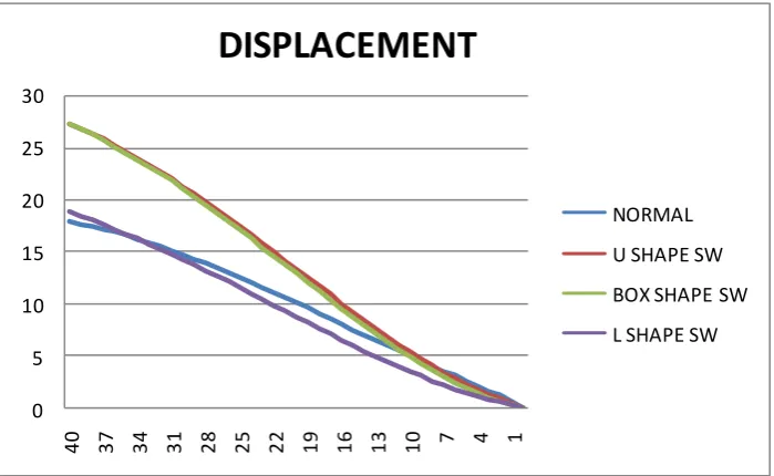
5.2 Graph showing Maximum Storey Displacement Values for 1.2(DL+LL+EQX) in Zone-2 & Soil-10 5 10 15 20 25 30
40 37 34 31 28 25 22 19 16 13 10 7 4 1
DISPLACEMENT
NORMAL
U SHAPE SW
BOX SHAPE SW
L SHAPE SW
Table showing Maximum Storey Displacement Values for 1.2(DL+LL+EQX) in Zone-2 & Soil-1
6 3.1 2.8 2.4 1.8
5 2.6 2.3 1.9 1.5
4 2.1 1.8 1.4 1.1
3 1.6 1.3 1 0.8
2 1.2 0.9 0.6 0.6
1 0.6 0.5 0.3 0.3
BASE 0 0 0 0
STOREY NORMAL U SHAPE SW BOX SHAPE SW L SHAPE SW
126 | P a g e
VI. DISCUSSION OF RESULTS
A 40storied building with shear wall & rigid frame structure with symmetrical shape (i.e. ‘I’ shape in plan)
is considered for analysis. Different shapes of shear walls with different locations in plan of the building
were analyzed in ETABS v2013 and results are obtained and compared.
Model 1: In this model building with 40 floors is modeled as a "'Rigid frame" with only, beams, columns &
slabs as shown .The dead loads of other elements (slabs, stairs and walls) are taken as member loads on the
respective beams.
Model 2: In this model building with 40 floors is modeled as Dual frame system with shear wall of Box
shape as shown. Shear wall acts as vertical cantilever with fixed end connected to the foundation. The loads
are taken same as in Model 1.
Model 3: In this model building with 40 floors is modeled as Dual frame system with shear wall of U shape
as shown . The loads are taken as same in Model 1.
Model 4: In this model building with 40 floors is modeled as Dual frame system with shear wall of ‘L’
shape as shown .The loads are taken as same in Model 1.
The building is analyzed using both the static and dynamic analysis methods for all models with different
shapes of shear walls
VI. CONCLUSIONS
The following conclusions are made from the present study
[1.] Provision of shear wall generally results in reducing the displacement because the shear wall increases the
stiffness of building and sustains the lateral forces. The better performance is observed in model 1 with
respect to diaphragm displacement because it has low displacement in both x and y directions than the
127 | P a g e
[2.] The shear force resisted by the column frame is decreasing by placing the shear wall and the shear force
resisted by the shear wall is increasing. This can be concluded indirectly by observing the maximum
column shear force and moment in both directions.
[3.] For the columns located away from the shear wall the Bending Moment is high and shear force is less
when compared with the columns connected to the shear wall. Torsion in the columns is decreased in the
model 3 with shear walls when compared to the model 1 without shear walls, from both the methods. The
torsion is also affected by the position and the shape of shear wall. For certain models it is increased and
for certain models it is decreased.
REFERENCES
[1.] IS: 456-code of practice for plain and reinforced concrete
[2.] IS: 875(part 1-5) - code of practice for structural safety of Building loading standards
[3.] IS 1893(Part-1):2002, Criteria for earthquake resistant design of structures.
[4.] IS 13920:1993, Ductile detailing of reinforced concrete structure subjected to seismic forces-code of
practice.