a
Corresponding author: [email protected]
On the recirculation zone suppression behind HUMP profile using the
DBD actuator
Pavel Procházka1,a, Václav Uruba1 1
Institute of Thermomechanics, Czech Academy of Sciences, Czech Republic
Abstract. Previously, the DBD (dielectric barrier discharge) plasma actuator was used in rectangular channel to modify the properties of the boundary layer in spanwise and in streamwise orientation. The actuator was redesigned for using on the surface of the Glauert-Goldschmied body in different position to influence the point of the separation and the reattachment point as well as the total extent of the separation bubble. The most intensive effect occurs when the actuator takes effect in the point of separation. Further downstream, the ionic wind produced by DBD causes complex coherent structures in the wake for spanwise orientation in both direction. The effect of streamwise orientation is studied also. Actuator is operated in steady regime to produces continuous ionic wind as well as in unsteady regime when the vortex street is generated. The properties of vortex street is given by modulation parameters (frequency and duty cycle). The effect of these parameters on the wake is evaluated. This experiment is realized in the perspex channel connected to the blow-down wind tunnel. The HUMP profile is flush-mounted to the bottom side. The wire electrode of the actuator is situated in x/L = 0.63, 0.66, 0.69 and 0.72 of the chord length. The time-resolved PIV (Particle Image Velocimetry) is used as a main measurement technique. The flow field behind the profile is captured in longitudinal plane as well as in cross-section planes using 3D PIV. The results based on statistical quantities will be presented in this paper. More, next part will be devoted to the decomposition analysis of the flow dynamics (BOD, OPD).
1 Introduction
This article is dealing with the possibility to control the form drag of the streamlined profile using plasma actuators. The plasma actuator belongs to the group of active flow control devices, such synthetic jets or moving surface devices. They have many advantages in comparison with other devices as low volume resulting in simple assembly, no mechanical breakable moving parts, low need for power and very high response time needed for sophisticated active flow control. On the other hand, they have quite low efficiency of energy conversion. However, their implementation into real application is relatively slow, since they have been developing for no longer than two decades. So that is why, the physical principle of the plasma discharge and its effect on the flow is not fully clarified. There are several numerical studies [1] of their influence on the boundary layer but the main lack of that approach is certain underestimation of the ionic wind thrust. From this perspective, the experimental studies are very important to supplement required pieces of knowledge. Nowadays, the most used type is called DBD (dielectric barrier discharge) actuator, which is powered by alternating current of very high voltage value.
There was tested a wire type of DBD actuator in steady air as well as in zero-pressure gradient boundary
layer developed in rectangular channel previously [2]. The plasma actuator was driven in steady regime as is typical (e. g. [3]) and also in unsteady regime [4]. This regime seems to be very convenient for the purpose of active flow control utilization and it will be presented in the text further. The plasma actuator can generate necessary thrust in spanwise orientation (the same or opposite sense as channel flow) or in streamwise orientation, when the thrust is generated in perpendicular direction [5]. It has been shown that plasma actuation can stabilize or destabilize the boundary layer. The biggest effect was observed for channel velocities between 5 and 10 m·s-1 when the velocity gain was about 10% in normalized velocity profile.
The HUMP profile, also GG profile (Glauert-Goldschied), was chosen as a test case for plasma actuation, since this profile - established by Seifert [6] – was used many times (e.g. [7]) in numerical studies as well as in experimental ones to control the flow around it. The results described in available literature will be helpful for comparison with other authors. The flow naturally separates in the rear section of the profile and the size of the recirculation zone is dependent on Reynolds number.
The approach of this study is fully experimental. The data treatment will be set in dependency on statistical or dynamical point of view. To get statistical indicators, the data acquisition time will be longer with lower acquisition frequency. The dynamics of this phenomenon will be studied from time-resolved data. Since the unsteady regime produces pseudo-periodical structures, the phase-locked measurement will be employed to suppress the random phenomena. The energy decomposition will be utilized and the results also from stereo PIV measurements will be shown.
2 Experiment description
2.1 Actuator description
The DBD actuator has to consist of at least two electrodes and a dielectric layer between them. The wire type of DBD actuator used for this study was developed and tested during long research along flat plate [5]. This type of actuator has proved that it can generate sufficient strong ionic wind to influence boundary layer and its plasma discharge is homogenous and constant in time. However, some changes in actuator design had to be made to enable the assembly on the hump surface.
The plasma actuator is flush-mounted onto the surface so it does not affect the flow field at all. Since the curvature of the Hump profile is significant, the use of the silica glass dielectric was not possible any more. Now, the dielectric is made from several layers of kapton foils (total thickness is 0,48 mm) which are curved perfectly to respect the original shape. The upper electrode is still thin wire (30μm) and is power by high-voltage high-frequency waveform. The lower electrode is made from copper foil and is grounded and encapsulated to set the discharge only at the top side. The electrode gap is set to approximately 3 mm. Several anchor points were utilized to lead the wire in desirable position. The wire was preloaded using spiral torsion spring which ensures the straight shape and constant distance from the lower electrode. The actuator was designed to enable fast change between four distinct positions on the hump surface. The actuator was applied in spanwise orientation to produce the ionic wind in the same direction as the channel flow and also in opposite direction.
2.2 Power source
The power source was designed especially for the power supply of this actuator type. It is conceived as a half-bridge circuit excitating output high voltage ferrite
transformer. This power source can give constant voltage value independently of the load. The voltage value can be set also independently and its maximal value is 12 kV in peaks (Ueff = 8,5 kV). The frequency is also adjustable in some range but for all time was set to value of 16 kHz. This source disposes of so-called shut-down function. This is used to modulate the voltage waveform. The rectangular modulation brings another two parameters – modulation frequency and duty cycle DC. These are used to control the vortical structures generated during unsteady regime.
The plasma actuator produces continuous ionic wind in steady regime where the power consumption is at maximal level. The maximal mean velocity in the ionic wind is up to 2 m·s-1. The dependency between applied voltage value and maximal velocity of the ionic wind is linear. After that rectangular modulation is applied, the vortices inside ionic wind can be observed (in steady air) which is the main property of the unsteady regime. Modulation frequency determines the length of one period. Modulation frequency determines also the vortex shedding frequency and their diameter. The rate between the time, when the plasma discharge is on and off, is determined by the duty cycle. Duty cycle determines the time during which the vortex is supplied by the energy of the ionic wind. Note, that DC=50% means that the power consumption of the electricity is half of the original value. Duty cycle of 30% means that plasma discharge is active for 70% of one period.
2.3 Experimental setup
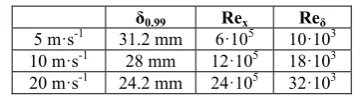
The hump profile was mounted inside perspex rectangular channel which was connected to the blow-down wind tunnel. The total length of the channel was 3000 mm and cross-section dimensions were 100 x 250 mm. The channel had rectangular corners and smooth walls made from transparent plate to enable optical access for laser and cameras. The turbulence intensity was 0.1% behind the contraction [8]. The profile was placed at the bottom side so that the distance between leading edge and the channel inlet was x = 1800 mm. The channel velocities were 5, 10 and 20 m·s-1. The boundary layer in front of the profile was fully developed turbulent. The boundary layer thickness at the leading edge and related Reynolds number are given at table 1.
Table 1. Boundary layer thickness and Reynolds number
į0.99 Rex Reį
5 m·s-1 31.2 mm 6·105 10·103 10 m·s-1 28 mm 12·105 18·103 20 m·s-1 24.2 mm 24·105 32·103
possible to the place where flow separates. However, it is not easy task to determine what is exactly the right spot of the ionic wind activity.
Four distinct actuator locations were tested. The wire position was chosen as the reference point. The first position located the most upstream was at x/L = 0.63 (63% of the chord length). This is 122 mm in horizontal sense from the leading edge. This position can be considered as slightly upstream of the separation point. Next three positions were at x/L = 0.66, 0.69 and 0.72. The second position is located slightly downstream of the natural separation point. And the last two positions are even further. These were established especially to test unsteady modulation as well as ionic wind oriented in opposite sense.
Figure 1. The hump profile, dimensions, zone of the actuation
2.4 Measurement technique
Time-resolved Particle Image Velocimetry (TR-PIV) was used as measurement method. The most measurement was acquired by standard 2D PIV in longitudinal plane perpendicular to the channel bottom side. To illuminate the tracing particles (safex generator of oil particles, diameter approx. 1 μm), the laser New Wave Pegasus Nd:YLF was utilized. The maximal repetition rate is 10 kHz. The energy of one pulse is 10 mJ for 1 kHz (10 W per head). This laser has double-head, cylindrical optics to make laser sheet with thickness of 1 mm and it emits the coherent light with wavelength of 527 nm. The CCD camera Phantom V711 was used to acquire the images in the plane of view. The total resolution is 1280x 800 and corresponding maximal acquisition frequency is 6 kHz in single frame mode. The camera memory is 8 GB. This camera was shifted along the field of view by a traverser to get sufficient space resolution.
The stereo PIV in cross-section plane was suggested to supplement the previous mentioned measurement. The goal was to reveal potential asymmetry of the flow. Two CMOS camera NanoSense MKIII with maximal resolution 1280 x 1024 pixels and corresponding acquisition frequency 512 double-images per second were utilized. The camera memory was 4 GB. These factors were limiting to get sufficient dynamical image of the flow. The Scheinpflug criterion was fulfilled. The precision of that method is within 1-2 %, if specific requirements are fulfiled [9]. The both cameras and laser sheet was shifted simultaneously by traverser system to measure in four distinct cross-section planes (x/L = 0.69, 0.87, 1.00 and 1.50).
Three regimes were investigated. The base case is without plasma actuation. There are results in the table 2.
The steady and especially unsteady regimes are used to suppress the size of the separation bubble. The plasma discharge is driven by maximal voltage value (12 kV for unsteady case, 8 kV for steady case). The effect of modulation frequency and duty cycle was studied. The frequency was measured for range from 10 to 500 Hz and duty cycle varied from 10 to 90%.
The mean flow field characteristics were evaluated from data acquired by 100 Hz and at least 6 seconds. The POD (Proper Orthogonal Decomposition) analysis was performed from data acquired by 2 kHz. Also phase-locked measurement was applied to highlight the periodical process by unsteady regime. There were acquired 20 phases per each period and then the averaging over at least 80 periods was performed.
3 Results
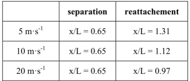
The table 2 shows the results of the different separation bubble size for three channel velocities. The separation point is still at the same place but the reattachement point is moving upstream with increasing Reynolds number. The main goal of the plasma actuation is to minimize the dimension of the recirculation zone – either by reattachement point shifting or by reduction of the zone thickness.
Table 2. Separation and reattachement point location without plasma actuation
separation reattachement
5 m·s-1 x/L = 0.65 x/L = 1.31
10 m·s-1 x/L = 0.65 x/L = 1.12
20 m·s-1 x/L = 0.65 x/L = 0.97
The figure 2 reveals the small section of the profile with the actuator placed at x/L = 0.63. The mean flow field is coming only from thrust generated by plasma actuator, channel flow is not present. Notice, that maximal velocity is close to the hump surface approx. 4 mm downstream. This implies that the position of the wire electrode is not crucial parameter by the making decision what is the right place to take effect. On the other hand, the plasma actuation evokes sufficiently strong suction effect to generate positive velocities of about half original magnitude in the vicinity of the wire electrode. The ionic wind is closely attached to the curved surface due to Coanda effect.
recirculation zone is present but very tiny and hardly evaluated from PIV data.
Figure 2. Ionic wind without channel flow
Figure 3. 5 m·s-1, plasma actuation off
Figure 4. 5 m·s-1, plasma actuation off
Figure 5. 10 m·s-1, plasma actuation off
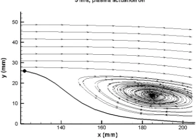
The plasma actuation applied in the first and second position has led to strong reduction of the separation (figure 6). The actuator in 63% of the chord length was able to fully suppress the separation. There is only small separation up to 0.77 for second position of the actuator. The situation is different, when the actuator is placed further downstream. In the third position, the ionic wind in not able to decrease this zone, there is only uncertain change of the separation bubble shape. There is the actuator placed in the last position (0.72) in the figure 7. The actuator is not able to attach the flow any more because even the suction effects are far away from the point of separation. The size of the bubble is approximately the same. However, the topology of the wake is not the same.
Figure 6. 5 m·s-1, plasma actuation on at 0.63
Figure 7. 5 m·s-1, plasma actuation on at 0.72
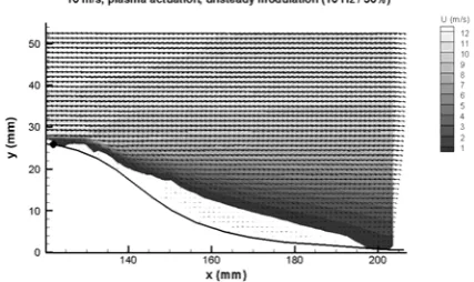
away from the electrode. This convective velocity is in order of tenths of m·s-1. The tendency is weakly growing with applied modulation frequency.
Figure 8. 5 m·s-1, actuation at 0.72, unsteady (10Hz/30%)
Also the effect of the ionic wind generated in opposite direction was tested. Here, the results obtained from the second position of the actuator will be presented. The separation bubble became greater in size of both dimensions for all three channel velocities. The separation point under 5 m·s-1 was shifted to x/L = 0.57 (instead of 0.65) and the reattachement point was shifted to x/L = 1.37 (instead of 1.31). The reattachement point of the double channel velocity was x/L = 1.26. The effect of opposite ionic wind is more dominant for the actuator positions located more upstream.
The effect of duty cycle is also crucial at the first position also. Duty cycle of 90% does not evoke the ionic wind for desirable time and flow separates at the identical point as in the base case and it creates quite huge recirculation zone (figure 10). Nevertheless, the size of separation bubble is approximately twice smaller and the reattachement point was shifted upstream to x/L = 1.08. Of course, this regime is not so competitive in comparison with steady actuation or actuation under DC = 30% but its energy consumption is only a fraction of the original value, more precisely one tenth.
The effect of modulation frequency value is demonstrated at the figures 11 and 12. It is obvious (especially from data acquired by phase-averaged measurement) that if the higher value of modulation frequency is used, the mean flow field is more attached to the surface. The flow is periodically attached to the surface and again separated from the surface according to modulation parameters. There is one switching reattachement/separation per period. With the higher modulation frequency applied (observed from 50 Hz), the flow is not able to follow this switching due to inertia forces and stays more or less attached to the surface for all time. Notice, that the frequency value is not responsible for power consumption, unlike the duty cycle.
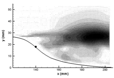
The last figure represents extracted second POD mode of the wake flow influenced by the actuator placed at the last position and driven by 10 Hz and 30% DC, channel velocity 5 m·s-1. The extracted POD mode contains probably the secondary vortical structure mentioned
Figure 9. 5 m·s-1, opposite plasma at 0.66
Figure 10. 5 m·s-1, actuation at 0.63, unsteady (10Hz/90%)
Figure 11. 5 m·s-1, actuation at 0.63, unsteady (10Hz/30%)
Figure 12. 5 m·s-1, actuation at 0.63, unsteady (200Hz/30%)
Figure 13. Second POD mode
Table 3. Five most important modes sorted by kin. energy
1 2 3 4 5 x/L = 0.72,
10 Hz 18.6% 9.1% 6.6% 4.8% 3.9%
x/L = 0.72,
20 Hz 26.3% 10.3% 6.5% 4.0% 2.5% x/L = 0.72,
50 Hz 15.3% 9.7% 6.5% 5.9% 4.6%
x/L = 0.66,
30% 26.6% 16.2% 5.5% 4.0% 3.5% x/L = 0.66,
70% 34.5% 17.7% 5.5% 3.8% 2.6%
4 Conclusion
The flow field behind hump profile was investigated experimentally using time-resolved Particle Image velocimetry. To control the separation point and the size of the recirculation bubble, the DBD wire actuator was used in steady and unsteady regime. The flow field was investigated from statistical and also from dynamical point of view. POD analysis was performed. Phase-locked measurements were conducted to detect secondary vortical structures present in the wake which are incorporated into the flow by the energy of plasma actuation.
The ionic wind is strength enough to fully suppress the area of negative velocity for lower channel velocities about 5 m·s-1. It was observed that the optimal actuator position was at x/L = 0.63 or 0.66 which is in a good
agreement with other authors. Nevertheless, the thrust coming from plasma actuation placed further downstream can significantly change the properties of the wake due to existence of secondary pseudo-steady vortical structure. The dimension of the separation bubble can be easily magnified by the ionic wind affecting the flow in the opposite sense.
The role of duty cycle is crucial. Higher value of duty cycle does not lead to considerable improvement but on the other hand, the energy consumption of these regimes is tiny. The effect of modulation frequency is also important. Higher frequency is more appropriate, since the flow is not able to follow the rapid changes and stay more or less attached to the surface.
Acknowledgement
The authors gratefully acknowledge financial support of the Grant Agency of the Czech Republic, No. GP14-25354P.
References
1. P. C. Dörr, M. J. Kloker, Procedia UITAM 14, 469-478 (2015)
2. P. Procházka, Dissertation thesis, VUT (2013)
3. Y. Li, X. Zhang, X. Huang, Exp. Fluids 49, 367-377 (2010)
4. N. Bénard, N. Balcon, G. Touchard, E. Moreau, Exp. Fluids 45, 333-355 (2008)
5. P. Procházka, V. Uruba, EPJ Web of
Conferences 114, 02099 (2016)
6. A. Seifert, L. G. Pack, AIAA Journal 40, No. 7, 1363-1372 (2002)
7. C. He, T. C. Corke, M. P. Patel, AIAA Journal, 0935 (2007)
8. P. Jonáš, O. Mazur, V. Uruba, IV.
Watermanagement conference, Prague (2004)