Thermal Performance of Buildings: Case
Study and Experimental Validation of
Educational Building
Mathew Joseph
1, Victor Jose
2,
Anjuman Habeeb
3Head of the Department, Dept. of Mechanical Engineering, MBC College of Engineering & Technology, Kerala, India1 Assistant Professor, Dept. of EEE, Amal Jyothi College of Engineering, Kerala, India2
PG Student [Energy Systems], Dept. of EEE, Amal Jyothi College of Engineering, Kerala , India3
ABSTRACT: Thermal performance of buildings refers to the process of modeling the energy transfer between the building and the surrounding. With the sound knowledge of energy associated with the building, energy efficiency of the building can be improved. To have a thorough understanding of the same a case study was included. The main objective behind the paper is to analyze the cooling loads associated within a system and thereby the capacity and sizing of the air conditioning equipment can be made. The estimation is based on the steady state approach. Different parameters like heat transfer modes, solar radiation geometry, evaporation, ventilation effects.etc contribute for the heat load estimation. The main purpose behind this is to avoid unwanted wastage in energy as a result of the conventional thumb rule approach. For better understanding, the simulation of heat load estimation in a room was done using LABVIEW software. With the help of simulation tool, different parameters can be monitored. The major heat load was contributed from internal heat gain. It accounts for about 6400W, a total of 42%.
KEYWORDS: Steady state approach, Heat transfer modes, Solar geometry, LABVIEW Simulation software.
I.INTRODUCTION
Thermal performance of a building refers to the process of modeling the energy transfer between a building and the surroundings. Understanding the thermal performance of buildings calculates the cooling load and hence it helps to estimate the capacity, size and selection of an air conditioning apparatus. For an unconditioned building, it calculates the temperature variation within a building. These are very essential and enable us to determine the effectiveness of the design of the building [1]. The design load is based on inside and outside design conditions. It is based on the estimation of steady state approach of various building elements such as wall, roof, door, etc. and the estimation of overall heat transfer rate.
II.HEAT TRANSFER MODES
For analyzing the thermal performance of the building, knowledge of various heat exchange processes are required. Various heat exchange processes are possible between a building and the external environment. Heat flows by conduction through various building elements such as walls, roof, door, windows.etc. Heat transfer also takes place from different surfaces by convection and radiation.
A. Ventilation
The heat flow rate due to ventilation of air between the interior of a building and the outside depends on the rate of air exchange. It is given by
Q v = 𝜌 V r C ∆T 𝜌 = density of air (kg/ m3)
V r = ventilation rate (m3/ s)
C = specific heat of air (J/ kg-K)
∆T = temperature difference (To – Ti) (K)
As the ventilation rate increases the heat flow due to ventilation increases. B. Solar heat gain
Solar gain through transparent elements
Qs =αs Σi=1M Ai Sgi τi
αs = mean absorptivity of the spaces
Ai =area of the ith transparent element (m2)
Sgi = daily average value of solar radiation on the ith transparent element (W/m2)
τi = transmissivity of the i th
transparent element M = number of transparent elements
III.SOLAR RADIATION
Sun is the sole source of energy. Sun is a star and is considered as a radiant energy source with surface temperature that is equivalent to a perfect black body at 6000K. Solar radiation stretching from 0.2microns - 4.75microns. Most of the solar radiation lies on the visible radiation and near infrared radiation. It is the only source of heat and light for the entire solar system. Heat is generated by means of various kinds of fusion reactions. Solar constant is defined as the flux of solar radiation on a surface normal to sun’s rays beyond the earth’s atmosphere at a mean earth-sun distance. Though the solar constant value varies with time, its accepted value is 1367W/m2. When solar radiation enters into the atmosphere, it gets depleted due to reflection, scattering and absorption.
A. Solar radiation geometry
The incident radiation depends on solar geometry involving several basic and derived angles. Some of the basic angles are:
1. Latitude (𝜑) indicates the location on the earth’s surface. It is the angle made by a radial line joining the given location to the centre of the earth with its projection on the equator plane. The latitude is positive for northern hemisphere and negative for southern hemisphere.
2. Declination (𝛿) is defined as the angular displacement of the sun from the plane of the earth’s equator. It is positive when measured above the equatorial plane in the northern hemisphere. It can be approximately determined from the equation
𝛿 = 23.45 * sin[360
365(284+n)] degrees
3. Hour angle (𝜔). The hour angle at any moment is the angle through which the earth must turn to bring the meridian of the observer directly in line with the sun’s rays.
4. Slope (𝛽), it is the angle between the inclined plane surface and the horizontal. It is taken to positive for the surface sloping towards south.
5. Surface Azimuth Angle (𝛾), it is the angle in the horizontal plane ,between the line due south and the horizontal projection of the normal to the inclined plane surface. It is taken as positive when measured from south towards west.
where r is the global radiation tilt factor
r = (1- Id
Ig
) r b + ( 1+cosβ
2 )
Id
Ig
+ ρ 1− cosβ
2
cosθ = sinφ(sinδcosβ+ cosδcosγcosωsinβ)+ cosφ (cosδcosωcosβ− sinδcosγsinβ)
+ cosδsinγsinωsinβ) cosθz =
sinφ sinδ+ cosφ cosδ cosω
Ig = mean hourly global solar radiation (W/m 2
) Id = mean hourly diffuse radiation(W/m2) 𝜌 = reflectivity of the ground surface
B. Steady state approach
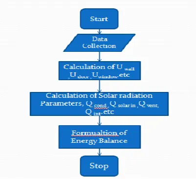
Heat transfer is the transfer of thermal energy from a body at a higher temperature to a body at a lower temperature. Transfer of heat or heat transfer modes can be modeled in two ways. Under steady state conditions the temperature variation does not change with time. Similarly under, unsteady state conditions the temperature within the system varies with time. Here to make the calculations simpler and easier steady state approach is preferred. In steady state approach the net heat influx is equal to net heat efflux. There is balanced heat load
within the system. Figure 2: Flow path of heat load
IV. ESTIMATION
Heat load estimation in a classroom is started by having a proper analysis on solar radiation geometry angles acting on each wall namely north, south, west and east. The overall heat transfer coefficient for wall, door, window etc is calculated. Formulated the energy balance equation. Figure 2. shows the flow path of heat load and the estimation of heat load in a room.
V. HEAT LOAD ESTIMATION
General data
Place : DC 408,Amal Jyothi College of Engineering, Koovappally, Kanjirappally, Kottayam Month : November 2014
Ventilation rate : 3 per hour Artificial light : 6 * 40W tube Latitude: 9˚ 34N
Longitude: 76˚ 47 E
.
Figure 3. Components of Heat Load Occupants : 60 (normal class hours; 24hrs occupancy) Window : 196cm * 160cm
Door : 240cm * 118cm on East side Wall thickness : 20cm (brick layer)
Plastering : 1cm both sides Ceiling plastering : 9mm thick(neglect) Floor : Tile plastering: 2cm Tile thickness : 1cm
A.overall heat transfer coefficients of different building elements
1. Overall heat transfer coefficient, U wall
Heat transfer coefficient of Brick tile, h1 = .798W/m 2K
Heat transfer coefficient of Cement plaster, h2 = 0.721W/m 2K
Length of cement plaster, L1 = .01m
Thermal conductivity of brick, k1 = 0.721 W/mK[1]
Length of brick, L2 = .20m
Thermal conductivity of brick , k2 = 0.798 W/mK[1]
Length of cement plaster outside, L3 = .01m ;
Thermal conductivity of brick, k3 = 0.721 W/mK[1]
Heat transfer coefficient of inside medium, hi =8.3 W/m2K[1]
Heat transfer coefficient of outside medium, ho = 22.7 W/m2K[1]
Rth = 0.4429 m2K/W
Uwall = 2.257 W/m 2
K
2. Overall heat transfer coefficient of door, U door
Thermal conductivity of timber, k timber =.072 W/mK
Length of door, Ldoor =2.4m
Width of door =3cm Breadth of door = 1.18m
Heat transfer coefficient of inside medium, hi =8.3 W/m2K
Heat transfer coefficient of outside medium, ho = 22.7 W/m2K
Thermal resistance, R th = 33.49 m2K/W
Area of the door, Area door = 2.4 *3 *10-2 m2
U door = 0 .414 W/m2K
3. Overall heat transfer coefficient of window, U window
Thermal conductivity of glass, kglass = 0 .814 W/mK
U wall = 2.93 W/m2K
4.Overall heat transfer coefficient of roof, Uroof - neglected.
B. Solar radiation geometry
Daily average outside temperature (November) - 30°c Absorptance of external wall surface - 0.6
Outside heat transfer coefficient, h - 22.7 W/m2K Inside design temperature - 23 °c Latitude at Kanjirappally - 9° 34′𝑁 Longitude at Kanjirappaly - 76° 47′𝐸
1. Daily average solar radiation on south east wall
𝛾 = −20, 𝛽 = 90, 𝛿 = −18.91, 𝜑 = 9.56, 𝜔 = 0
Cos 𝜃 = 0.44795 Cos 𝜃Z = 0.8790
rb = 0.50951
r = .6053
IT = 1457.56W/m2
2. Daily average solar radiation on south west wall
𝛾 = 70, 𝛽 = 90, 𝛿 = −18.91, 𝜑 = 9.56, 𝜔 = 0
Cos 𝜃 =0.1630 Cos 𝜃Z = 0.8790
rb = 0.1854
r = 0.4254 IT = 1024.5 W/m2
3.Daily average solar radiation on north west wall
𝛾 = 160, 𝛽 = 90, 𝛿 = −18.91, 𝜑 = 9.56, 𝜔 = 0
Cos 𝜃 = -0.44795 Cos 𝜃Z = 0.8790
rb = -0.50951
r = 0.04017 IT = 96.74W/m2
4. Daily average solar radiation on north east wall
𝛾 = 110, 𝛽 = 90, 𝛿 = −18.91, 𝜑 = 9.56, 𝜔 = 0
Cos 𝜃 = -0.1630 Cos 𝜃Z = 0.8790
rb = -0.1854
r = .2199 IT = 529.55 W/m2
C. NET HEAT BALANCE
Q total = Qc + Qs + Q i + 𝑄 𝑣
Heat flow due to ventilation, Q v = 2736.79 W
Internal heat gain, Q I = 6440W
Solar heat gain, Qs =2708.08 W
Heat flow due to conduction, Qc = 1446.55W
Qtotal = 15635.31W
Therefore it requires a 4.44TR air conditioning equipment. Heat load estimation in a room was carried out. It is found that for a 100m2 room require a 4TR of air-conditioning equipment. It was estimated for solar noon, therefore it will be having a maximum consumption of power during the day.
VI. SIMULATION SOFTWARE
The simulation of heat load estimation is done using LABVIEW software. It offers several circuit linked operations that can work similar to coded computer languages and provide the output for given input and pre-initialized values. The user interface consists of
a) Front Panel – where the input and output are shown to the user.
b) Block Diagram – where the programmer draws the circuit diagram required for the program.
In the program, the input is fed into a “control” and the output is displayed as an “indicator”. The operations are done in the block diagram page and controls and indicators are placed in the front panel.
LabVIEW stands for Laboratory Virtual Instrument Engineering Workbench. It was developed by National Instruments to provide a visual programming environment. The latest version of labview is LabVIEW 2013. Execution of commands is as per the graphical block diagram in which the programmer connects functions by wires.
A. Advantages
i. The graphical environment allows non programmers to develop programs by the drag and drop method. ii. It includes a compiler that creates a code for the CPU platform. At the same time, the compiler also detects the
presence of any errors.
iii. A major advantage of the LabVIEW compiler over other coding softwares such as C, C++, etc is that it points out the location of the error. This saves time and lessens effort of the programmer in searching for the error location, especially in lengthy programs.
iv. LabVIEW has a large library comprising of numerous arithmetic, logical trigonometric, array, matrix and many other types of functions. This helps in reducing code length to a considerable extent.
v. Code re-use is allowable as long as data types of input and output are consistent.
Parallel Programming can be done by which processes such as test sequencing, hardware interfacing and data recording can be done at the same time.
VII.RESULTS AND DISCUSSION
The paper deals with the study of thermal performance of buildings using steady state approach. Once optimised properly the proper fixation of equipments can be done effectively. By the sub optimal design the energy savings can be achieved.
A. Interpretations
i. One dimensional steady state heat transfer through buildings, it is possible only when outdoor and indoor temperature do not vary with time.
ii. The thickness of the building wall is small when compared with other two dimensions. iii. Building walls are multi-layered, non homogenous and non isotropic.
iv. Unshaded area is considered.
v. Overall heat transfer coefficient of ceiling is neglected.
B. Observation
1. South wall will have maximum hourly radiation. East and west wall has less radiation. North wall has comparable value.
2. The building is 20°inclined with respect to east direction.
C. Results
1 Total heat gain rate Positive 2 Total heat entering the building 15kW 3 COP of a standard air conditioner of 1.5tons
cooling capacity
2.8
4 Power required 5.35kW
5 If the machine is used for 8 hours a day 42.8units consumption & Rs.171.2/-expense daily. 6 Internal heat gain contribution More
REFERENCES
[1] J K Nayak., Handbook on Energy Conscious buildings, IIT Mumbai.
[2] Sukhatme S P., Nayak J K., Solar energy, 2nd Edition, Tata McGraw Hill, New Delhi, 1996.
[3] Brittany Hanam.,Development of an open source Hourly Building Energy Modeling Software Tool , Waterloo, Canada,2010 [4] http://www.energyplus.gov( December 2013)
[5] http://www.doe2.com/equest(January 2014 )
[6] John Twidel.,Tony Weir., Renewable Energy Sources., 2nd Edition,taylor and Francis