Volume 2010, Article ID 249826,13pages doi:10.1155/2010/249826
Research Article
Improved Steganographic Method Preserving Pixel-Value
Differencing Histogram with Modulus Function
Jeong-Chun Joo,
1Hae-Yeoun Lee,
2and Heung-Kyu Lee
11Department of Computer Science, Korea Advanced Institute of Science and Technology, 335 Gwahangno, Yuseong-Gu, Daejeon 305-701, Republic of Korea
2School of Computer and Software Engineering, Kumoh National Institute of Technology, Yangho-Dong, Gumi, Gyeongbuk 730-701, Republic of Korea
Correspondence should be addressed to Heung-Kyu Lee,[email protected]
Received 20 August 2009; Revised 4 February 2010; Accepted 20 March 2010
Academic Editor: Bulent Sankur
Copyright © 2010 Jeong-Chun Joo et al. This is an open access article distributed under the Creative Commons Attribution License, which permits unrestricted use, distribution, and reproduction in any medium, provided the original work is properly cited.
We herein advance a secure steganographic algorithm that uses a turnover policy and a novel adjusting process. Although the method of Wang et al. uses Pixel-Value Differencing (PVD) and their modulus function provides high capacity and good image quality, the embedding process causes a number of artifacts, such as abnormal increases and fluctuations in the PVD histogram, which may reveal the existence of the hidden message. In order to enhance the security of the algorithm, a turnover policy is used that prevents abnormal increases in the histogram values and a novel adjusting process is devised to remove the fluctuations at the border of the subrange in the PVD histogram. The proposed method therefore eliminates all the weaknesses of the PVD steganographic methods thus far proposed and guarantees secure communication. In the experiments described herein, the proposed algorithm is compared with other PVD steganographic algorithms by using well-known steganalysis techniques, such as RS-analysis, steganalysis for LSB matching, and histogram-based attacks. The results support our contention that the proposed method enhances security by keeping the PVD histogram similar to the cover, while also providing high embedding capacity and good imperceptibility to the naked eye.
1. Introduction
Steganography is a method of secret communication in which a message is embedded in a cover, such as text or an image. Message embedding is performed in spatial or frequency domain. One of the representative data hiding methods in spatial domain is to use the least significant bit (LSB), such as LSB replacement or LSB matching. Transform domain steganographic methods employ the well-known transformation techniques such as Discrete Cosine Trans-form (DCT), Fourier TransTrans-form (FT), or Discrete Wavelet Transform (DWT). Spatial domain methods are simpler and have a large capacity while transform domain methods are more robust compared to spatial domain method. The key factors for the secure communication are high security, high embedding capacity, and good imperceptibility to the naked eye. In order to satisfy these requirements, a number
of different steganographic algorithms have been developed with the primary aim of maintaining the characteristics of the cover image such as histogram to avoid any statistical attack [1–3].
Steganalysis schemes can be classified into two categories: specific and universal steganalysis. Due to the fact that specific steganalysis attempts to detect a specific target steganography [4,5], it has high performance when tested only on that precise embedding method. Universal steganal-ysis is designed to reveal a hidden message regardless of the steganographic algorithm used [6–8]. Although universal steganalysis performs slightly worse than specific steganalysis techniques where the stego method is assumed known, it nevertheless yields acceptable results. Universal steganalysis therefore appears to be the more practical solution.
the properties of the human visual system, Wu and Tsai [9] proposed a Pixel-Value Differencing (PVD) steganography that embeds more bits into pairs that have large PVD values, such as those found in edge areas. Although this method provides high embedding capacity and invisibility, it creates step effects in the PVD histogram and embedded messages may be detected. A modified version of PVD steganography was presented by Zhang and Wang [10], which removed the step effects by varying the lower and upper bounds of the subrange using a pseudorandom parameterβ(∈[0, 1]). Since the random expansion of the subrange allowed fewer bits to be embedded for the same difference values and decreased the changing quantity of the pixel value, Zhang and Wang’s method had lower embedding capacity but better quality than Wu and Tsai’s. Though it made the histogram smooth, it was still detected by Sabeti et al. by the use of one-more-time embedding and neural networks [11]. Although a hybrid steganography was proposed using LSB steganography at flat areas and PVD steganography at edge areas in order to increase the embedding capacity [12], it still contained step effects and was detected by applying aχ2 -attack on the PVD histogram [13]. More recently, a stegano-graphic algorithm using PVD and the modulus function was presented by Wang et al.[14], in which the remainder of two consecutive pixels was changed to match the decimal value of the message bits. However, the embedding process created fluctuations and abnormal increases, which destroyed the symmetry of the PVD histogram. Wang et al.’s method was therefore detected using a PVD histogram-based attack [15]. Yang et al. suggested the adaptive LSB steganographic method using PVD to determine the length of the message bits [16], which divides the range of difference values into lower, middle, and higher levels.
In our assessment of all the previous PVD stegano-graphic techniques described herein, we found that detection occurred because the embedding process changed the PVD histogram too severely. In order to achieve the required level of security, the embedding process must avoid those attacks that exploit modifications to the PVD histogram and eliminate all artifacts generated by the embedding process. In view of these assessments, the aim of this paper is to introduce improvements on Wang et al.’s method in terms of higher capacity and lower detectability, while being secure against well-known steganalytic methods. The use of the modulus function improves capacity by overcoming the falling-off-boundary problem and provides good image quality by minimizing the changes in pixel values [17,18]. The proposed method makes two main contributions to steganographic technique: a turnover policy and a novel adjusting process. The turnover policy yields histograms close to those of the cover image and maintains the symmetry of the PVD histogram. The novel adjusting process helps to remove fluctuations around the border of the subrange. The proposed method therefore maintains the PVD histogram similar to that of the cover and is secure against RS-analysis [4], steganalysis for LSB matching [5], and histogram-based steganalysis that focuses on PVD steganographic methods [10, 15]. Furthermore, high capacity and good imperceptibility are achieved.
The remainder of the paper is organized as follows.
Section 2provides a review of Wang et al.’s steganographic algorithm and describes its weaknesses in the face of steganalytic measures. InSection 3, we present our secure steganographic algorithm, including a turnover policy and a novel adjusting process. Experimental results are presented inSection 4andSection 5concludes.
2. Review of Wang et al.’s Method
2.1. Wang et al.’s Steganographic Algorithm. For high embed-ding capacity and good image quality, Wang et al. proposed steganography using PVD and a modulus function [14]. It modifies the remainder of two consecutive pixels instead of the difference between them.
In order to embed the message bits, five parameters are obtained for each subblockFi, each of which is composed
of two consecutive pixels (P(i,x),P(i,y)) using Wu and Tsai’s scheme [9], namely, the differencedi = P(i,y)−P(i,x), the subrange Rk such that Rk ∈ [lk,uk] andlk ≤ di ≤ uk,
the widthwk = uk −lk + 1, the embedding capacity ti
(bits), and the decimal value ti of ti message bits. The
remainder values Frem(i) are then calculated by dividing (P(i,x)+P(i,y)) by 2ti. A range table Rprovides data on the embedding capacity of each sub-blockFi and is composed
ofncontiguous subrangesRk(0 ≤ k < n).tibits of secret
data S are embedded into Fi by altering P(i,x) and P(i,y) such thatFrem(i) = ti, using the approach that achieves
the minimum distortion. When the stego pixel values (P(i,x),P(i,y)) do not overflow the boundary of the grayscale pixel value ([0 255]), the embedding process is completed following the replacement of (P(i,x),P(i,y)) by (P(i,x),P(i,y)) in the cover image. When P(i,x) or P(i,y) overflows, P(i,x) and P(i,y) are revised by adding 2(ti−1), subtracting 2(ti−1), or shifting the overflowing values. Since (P(i,x),P(i,y)) can be corrected, the range of the revised stego pixel values (P(i,x),P(i,y)) may neither fall below 0 nor rise above 255. Finally, the embedding process is completed by replacing (P(i,x),P(i,y)) in the cover image by (P(i,x),P(i,y)).
In order to extract the message bits, the receiver obtains the differencedibetween two consecutive pixels (P(i,x),P(i,y)). di determines the subrange index k, the width wk of the
subrange bywk=uk−lk+ 1 and the lengthtiof the message
bits. After computing the remainder value usingFrem(i) = (P(i,x)+P(i,y)) mod 2ti, the extraction algorithm is completed by transforming the remainder value Frem(i) into a binary string of lengthti.
2.2. Steganalytical Weaknesses of Wang et al.’s Method. In [15], we presented three steganalytic measures to detect a message that was embedded using Wang et al.’s method. Although Wang et al.’s method achieves high embedding capacity and good imperceptibility, the significant changes in the PVD histogram reveal the existence of the messages.
difference between the two pixels.Table 1shows an example of how the pixel pair changes when the message value is embedded using Wang et al.’s method. After embedding the messages, the difference of two stego pixels is changed by 1, at most. For example, if the cover pixel pair is (9, 8), its original difference is−1 and the difference of the stego pixel pair becomes−1 or 0. In general, in a negative area (d <0), dis changed todor (d+ 1), while in a positive area (d >0), dis changed todor (d−1). This means that the absolute value of the difference between two pixels is unchanged or decreased by 1 after embedding. However, since there are no absolute values smaller than 0, a change ofh(0) violates the general modification rule. We therefore model the changes in the PVD histogram from the cover as per (1):
h(d)=
⎧ ⎪ ⎪ ⎪ ⎪ ⎪ ⎪ ⎪ ⎪ ⎪ ⎪ ⎪ ⎪ ⎪ ⎪ ⎪ ⎪ ⎪ ⎪ ⎪ ⎪ ⎨ ⎪ ⎪ ⎪ ⎪ ⎪ ⎪ ⎪ ⎪ ⎪ ⎪ ⎪ ⎪ ⎪ ⎪ ⎪ ⎪ ⎪ ⎪ ⎪ ⎪ ⎩
1−α 2
·h(d) +α 2
·h(d−1), ifd <0;
α
2·h(d−1)+
1−α 2
·h(d) +α
2 ·h(d+ 1), ifd=0 or 1;
1−α 2
·h(d)+α 2
·h(d+ 1), ifd >1,
(1)
whereαis the embedding rate.
The weaknesses of Wang et al.’s method are caused by these changes in the PVD histogram. Since there are some special cases that do not follow the general modification rule of (1),haround the lower and upper bound of the subrange are computed using (2):
h(uk−1)=
1−α 2
·h(uk−1);
h(lk+ 1)=α
2·h(lk) +
1−α 2
·h(lk+ 1)+α
2·h(lk+ 2), (2)
whereuk andlk are the upper and lower bound of thekth
subrange.h(uk−1) decreases andh(lk+ 1) increases after the
message is embedded. The first steganalytic measure (SM1) checks the fluctuation using (3):
SM1=h(−9)−h(−7)
h(−7) ×100. (3)
Because the width of each subrange is taken to be a power of 2,−8 is the common border in the various range tables. Since the PVD histogram valueh(d) decreases by increasing |d| in a macroscopically smooth fashion [9], two points (−7,−9) adjacent to the common border (−8) are used to obtain the maximum difference. In order to normalize and maximize the effects of the message embedding,h(−7) is used as the divisor.
Due to the fact that the difference histogram for natural images without embedding the message follows a Gaussian
distribution [19], the PVD histogram has bilateral symmetry about zero. The second steganalytic measure (SM2) therefore checks the asymmetry using (4).
SM2=h(1)−h(−1)
h(−1) ×100. (4)
As shown in (1), since h(1) and h(−1) is obtained from 3 bins (h(0),h(1),h(2)) and 2 bins (h(−1),h(−2)) of the original PVD histogram, respectively, h(1) is higher thanh(−1). Therefore,SM2 of the cover image is close to 0 andSM2 of the stego image is very much higher than 0.
After the message has been embedded using Wang et al.’s method, h(0) is generated from 3 bins (h(−1),h(0),h(1)) and increases significantly. The third steganalytic measure (SM3) checks for the abnormal increase of h(0) using the following equation:
SM3=h(0)−he(0)
he(0) ×
100, (5)
wherehe(0) is estimated close to the original value using the
curve-fitting methods of three well-known models described in [15]. Thus, SM3 of the cover image is close to 0. However, Wang et al.’s embedding process increases both h(0) andSM3.
The values of the three steganalytic measures for the cover and stego images can be separated from each other and can hence reveal the existence of the hidden messages embedded using Wang et al.’s method without the cover images. The performance of the steganalytic measures used is described and verified by experiment (seeFigure 7).
3. Proposed Steganography
Preserving the PVD Histogram
To achieve secure steganography, the PVD histogram of the stego image should preserve the statistical properties of the cover image as well as possessing good visual quality. This section presents an improvement to Wang et al.’s method that generates no artifacts in the PVD histogram after embedding the message and is not detected using well-known steganalytic techniques or PVD histogram-based attacks. Firstly, the improved embedding algorithm with the turnover policy and the novel adjusting process is explained and then the extraction algorithm is presented without the cover images.
Table1: Changes in pixel values when embedding the message value using Wang et al.’s method. The differencedibetween two stego pixels
remains intact or is modified by±1.
(P(i,x),P(i,y)) Decimal message value Changes of differencedi
0 1 2 3 4 5 6 7
(10, 8) (9, 7) (9, 8) (10, 8) (10, 9) (11, 9) (11, 10) (12, 10) (8, 7) −2⇒ −2,−1 (9, 8) (8, 8) (9, 8) (9, 9) ( 10, 9 ) (10, 10) (11, 10) (7, 7) (8, 7) −1⇒ −1, 0 (8, 8) (8, 8) (8, 9) (9, 9) (9, 10) (10, 10) (6, 7) (7, 7) (7, 8) 0⇒0, 1 (8, 9) (8, 8) (8, 9) (9, 9) (9, 10) (10, 10) (10, 11) (7, 7) (7, 8) 1⇒1, 0 (8, 10) (7, 9) (8, 9) (8, 10) (9, 10) (9, 11) (10, 11) (10, 12) (7, 8) 2⇒2, 1
P(i,y)in turn. Therefore, the absolute value of the difference between two pixels can be decreased or increased. Since the difference between two pixels may be altered in a positive or negative way, the new histogramh(d) of the stego image is obtained from 3 bins (h(d−1),h(d),h(d+ 1)) of the original histogram (refer to Table 2). Consequently, the turnover policy preventsh(0) andh(1) from increasing abnormally and helps to make the PVD histogram symmetric about zero in a similar way to the cover. As a result,SM2 andSM3, as described in Section 2.2, are no longer effective. Our novel adjusting process is applied to solve the out-of-subrange problem, which opens the algorithm to possible detection bySM1. Whereas Wang et al.’s method creates fluctuations around the border of the subrange, the proposed adjusting process eliminates these. Therefore, the proposed method is secure against detection bySM1.
The overall embedding process is shown in Figure 1. The proposed steganographic algorithm consists of four steps, namely, the pixel pairing step, the embedding step, the adjusting step, and the overcoming step. The pixel pairing step vectorizes the pixel pairs and permutates the sub-blocks. At the embedding step, the message bits are embedded into the pixel pair using the modulus function and turnover policy. The adjusting step employs our novel adjusting process when the difference in the new pixel pair is below or above the subrange. Finally, the falling-off -boundary problem is solved at the overcoming step. The embedding process is repeated until no messages or pixel pairs remain.
Firstly, in the pixel pairing step, the cover image is partitioned into nonoverlapping sub-blocks composed of two consecutive pixels by Zigzag scan. To enhance the security, the sub-blocks are permutated.
In the embedding step, the remainder of two pixels is simply modified to match the message value. Given that the modulus function is used, the proposed method reduces or increases the pixel value to match the residue of the pixel pair to the decimal message valueti.mis a modifying value used
to minimize the distortion as per Equation (6):
m= ⎧ ⎪ ⎪ ⎪ ⎪ ⎪ ⎪ ⎪ ⎨ ⎪ ⎪ ⎪ ⎪ ⎪ ⎪ ⎪ ⎩
ti−Frem(i), ifti−Frem(i)≤wk 2 ;
ti−Frem(i)−wk, if ti−Frem(i)
> wk 2 ;
ti−Frem(i)+wk, if ti−Frem(i)
<−wk
2 , (6)
whereFrem(i)is the remainder of the sum of the two pixels (P(i,x)+P(i,y)) divided by the widthwk of subrangeRk. In
order to embed the message, the two pixels are modified using (7):
P(i,x),P(i,y)
= fP(i,x),P(i,y)
,m = ⎧ ⎪ ⎪ ⎪ ⎪ ⎪ ⎪ ⎪ ⎪ ⎨ ⎪ ⎪ ⎪ ⎪ ⎪ ⎪ ⎪ ⎪ ⎩
P(i,x)+rc,P(i,y)+rf
,
ifiis odd number;
p(i,x)+rf,p(i,y)+rc
,
ifiiseven number,
(7)
where m is the modifying value obtained from (6), rc =
m/2 , and rf = m/2. Since the turnover policy is
employed in (7) to obtain the new stego pixels (P(i,x),P(i,y)), the changing opportunities are distributed nearly equally over the two pixels in the sub-block. Each histogram value therefore has the same probability of being changed, and the proposed method preserves the shape of the PVD histogram more closely to that of the cover.
The third (adjusting) step is designed to eliminate the fluctuations in the PVD histogram. After modifying the pixel values according to the decimal message value ti, whether
or not the out-of-subrange problem is present is checked by investigating whether the new difference of two stego pixels is in a different subrange. In order to solve the out-of-subrange problem by preserving the difference between two pixels, a novel adjusting process is devised using (8).
P(i,x),P(i,y)
= ⎧ ⎪ ⎪ ⎪ ⎪ ⎪ ⎪ ⎪ ⎨ ⎪ ⎪ ⎪ ⎪ ⎪ ⎪ ⎪ ⎩
g P(i,x),qx
,g P(i,x),qx
+di
,
ifiisoddnumber;
gP(i,y),qy
−di,g
P(i,y),qy
,
ifiisevennumber, (8)
wheredi=P(i,y)−P(i,x),g(p,q)= {p/wk−q}×wk+ti(q∈
{−1, 0, 1}),qx = arg minq∈{−1,0,1}|g(P(i,x),q)−P(i,x)|,qy =
arg minq∈{−1,0,1}|g(P(i,y),q)−P(i,y)|. In other words,g(p,q) is the closest value to p among all the values that have a residuetibywk. When the new differencedi of the altered
pixels (P(i,x),P(i,y)) is not zero (di=/ 0) and is in the other
subrange or at the border of the subrange (di ≤lk oruk ≤
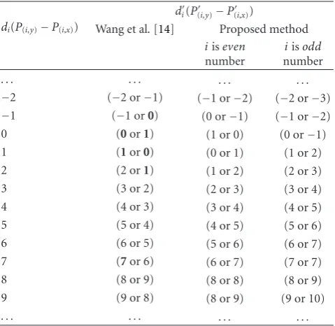
Table2: PVD changes after embedding, using Wang et al.’s method and the proposed method.
di(P(i,y)−P(i,x))
di(P(i,y)−P(i,x))
Wang et al.[14] Proposed method
iiseven
number
iisodd
number
. . . . . . . . . . . .
−2 (−2 or−1) (−1 or−2) (−2 or−3)
−1 (−1 or0) (0 or−1) (−1 or−2)
0 (0or1) (1 or 0) (0 or−1)
1 (1or0) (0 or 1) (1 or 2)
2 (2 or1) (1 or 2) (2 or 3)
3 (3 or 2) (2 or 3) (3 or 4)
4 (4 or 3) (3 or 4) (4 or 5)
5 (5 or 4) (4 or 5) (5 or 6)
6 (6 or 5) (5 or 6) (6 or 7)
7 (7or 6) (6 or 7) (7 or 7)
8 (8 or 9) (8 or 8) (8 or 9)
9 (9 or 8) (8 or 9) (9 or 10)
. . . . . . . . . . . .
the other pixel is adjusted to maintain the PVD. Therefore, the proposed method can maintain h(uk) and h(lk + 1)
similar toh(uk) andh(lk+1), respectively. There is no need to
apply the proposed adjusting process at the subrange which is greater than 128 because the histogram value is very small (close to 0). Due to the fact that the proposed adjusting process is able to remove the fluctuations around the border of the subrange, this weakness of Wang et al.’s method is eliminated and secure communication can be guaranteed.
Table 2shows how the difference value of the pixel pair
is changed after the messages have been embedded. The changes of the difference value represent the weaknesses of Wang et al.’s method and the advantages of the proposed method. In Wang et al.’s method, the new difference value di appears once (7), twice, or three times (0, 1). However,
since the proposed method increases or decreases the diff er-ence value, every di appears four times. Consequently, the
proposed method ensures a balance of changing opportunity for the difference value through the turnover policy and the novel adjusting process. It avoids histogram-based attacks by keeping the PVD histogram of the cover.
The fourth (overcoming) step is carried out in order to deal with the falling-off-boundary problem. If the pixel value is out of boundary [0 255] after the adjusting step, the overcoming step revises the pixels as follows.
Case 1. P(i,x)<0 andP(i,y)≤(255−z):
P(i,x),P(i,y)
=
P(i,x)+z,P(i,y) +z
. (9)
Case 2. P(i,x)<0 andP(i,y)>(255−z):
P(i,x),P(i,y)
=
0,P(i,y) +0−P(i,x). (10)
Case 3. P(i,x)>255 andP(i,y)≥z:
P(i,x),P(i,y)
=
P(i,x)−z,P(i,y)−z
. (11)
Case 4. P(i,x)>255 andP(i,y)< z:
P(i,x),P(i,y)
=
255,P(i,y) +P(i,x)−255. (12)
where
z=
⎧ ⎪ ⎪ ⎨ ⎪ ⎪ ⎩
wk, ifdi=lk ordi =uk;
wk
2 , otherwise.
(13)
This overcoming step was devised forP(i,x). In case ofP(i,y), we apply the same technique by substitutingP(i,x)withP(i,y). If the stego pixel pair is obtained without using the adjusting process, the overcoming valuezis half of the width, in order to preserve the remainder of the summation of the values of the two pixels. However, if the difference of the stego pixel pair is equal to the lower or upper bound of the subrange,z is equal to the whole width of the subrange that is required, so as not to change the remainder of each pixel. Most falling-off-boundary problems may be categorized as Case1or Case
3. However, since the solution of Case1and Case3can make another falling-off-boundary problem when the difference is greater than 128, Case 2 and Case 4 are designed. For example, if the pixel pair of the cover is (255, 43) and message value is 66, the underflow problem occurs after solving the overflow problem by Case3. To overcome this special case, Case4is applied and the new stego pixel pair is finally to be (255, 67).
After the overcoming step, the next pixel pair is selected and the embedding algorithm is applied repeatedly until no messages or pixel pairs remain.
3.2. Extracting Algorithm. The embedded messages are sim-ply extracted from the sum of two pixels or from one pixel. This extraction algorithm performs blind, without the cover. The sender and receiver must share the range tableR. The difference di is computed from two consecutive pixels
(P(i,x),P(i,y)) and determines the subrange indexk, widthwk,
and message lengthti. Ifdiis not zero and equal tolkoruk,
the message valueti is extracted merely by computing the
residue ofP(i,x)orP(i,y)bywk. If not,tiis the remainder value
of the sum of two pixel values bywk. The extracting process
for two pixels is completed by transforming the message value ti into a binary stream of length ti. The extracting
algorithm is performed repeatedly until no messages or pixel pairs remain.
Cover image
Stego image
1.Pixel pairing step Vectorize the pixel pair
by Zigzag scan 161 160 161 161 163
· · ·
160 159 155 159 159
· · ·
Permutate sub-blocks 161 163 161 161 160
· · ·
155 159 159 160 159
· · ·
Do until no messages or EOF MessageM
IV Overcoming
step
III Adjusting
step
II Embedding
step
P(i,x) P(i,y)
Select next sub-blocks (P(i,x),P(i,y))
Figure1: Overall message embedding process showing the pixel paring step, the embedding step, the adjusting step, and the overcoming step.
Sender
Cover image Stego image
(32, 32)
Msg: 3 Proposed
steganograhy (33, 34)
Covert channel
Receiver
Msg: 3
(33, 34) Stego image
Extract message (33 + 34) %8 (a) Message is embedded into the cover-image
Sender
Cover image Stego image Stego-stego image
(32, 32)
Msg: 2 Msg: 3
Wu and Tasi’s steganograhy
Proposed steganograhy (31, 33)
Covert channel
Receiver
Msg: 3
(32, 35) (32, 35)
Stego-stego image
Extract message (32 + 35) %8 (b) Double embedding: Message is embedded into the stego image
Figure2: Receiver can extract the hidden message correctly whether the message is embedded into the cover image (a) or stego image (b).
4. Experimental Results
In order to verify the minimum changes of the PVD his-togram, the proposed method was compared with the meth-ods of Wu and Tsai [9], Zhang and Wang [10], Wang et al. [14], and Yang et al. [16]. The stego images were generated using the range tableR inTable 3. In Yang et al.’s method [16], the parameters for the lower, middle, and higher levels were set as (2-3-4). The security was tested using RS-analysis [4], steganalysis for LSB matching[5], and the
Cover
Stego
Difference
(a) Baboon (b) Boat (c) Elaine (d) House
Cover
Stego
Difference
(e) Jet (f) Lake (g) Lena (h) Peppers
−10 −8 −6 −4 −2 0 2 4 6 8 10 Pixel difference
2000 3000 4000 5000 6000 7000
Oc
cur
renc
e
times
(a) Baboon
−10 −8 −6 −4 −2 0 2 4 6 8 10
Pixel difference 2000
3000 4000 5000 6000 7000 8000 9000 10000
Oc
cur
renc
e
times
(b) Boat
−10 −8 −6 −4 −2 0 2 4 6 8 10
Pixel difference 2000
3000 4000 5000 6000 7000 8000 9000 10000 11000
Oc
cur
renc
e
times
(c) Elaine
−10 −8 −6 −4 −2 0 2 4 6 8 10
Pixel difference 0.2
0.4 0.6 0.81 1.2 1.4 1.6 1.82 2.2
×104
Oc
cur
renc
e
times
(d) House
−10 −8 −6 −4 −2 0 2 4 6 8 10
Pixel difference
×104
0.5 1 1.5 2
Oc
cur
renc
e
times
(e) Jet
−10 −8 −6 −4 −2 0 2 4 6 8 10
Pixel difference 2000
3000 4000 5000 6000 7000 8000 9000 10000 11000
Oc
cur
renc
e
times
(f) Lake
−10 −8 −6 −4 −2 0 2 4 6 8 10
Pixel difference 2000
4000 6000 8000 10000 12000 14000 16000 18000
Oc
cur
renc
e
times
Cover Wang et al.’s Proposed
(g) Lena
−10 −8 −6 −4 −2 0 2 4 6 8 10
Pixel difference 2000
4000 6000 8000 10000 12000
Oc
cur
renc
e
times
Cover Wang et al.’s Proposed
(h) Peppers
Table3: Range tableR.lkandukare the lower and upper bound of
the subrange, respectively.
index (k) 0 1 2 3 4 5
[lk uk] [0 7] [8 15] [16 31] [32 63] [64 127 ] [128 255]
hiding bits (ti)
3 3 4 5 6 7
Table4: Mean of distance measures between the PVD histogram of the cover and that of the stego images for the eight test images.
Manhattan dist. (L1) Euclidean dist. (L2) Chi-square dist. Wu and
Tsai [9] 45101.5 9747.3 6139.7
Zhang and
Wang [10] 18056.0 4523.0 1257.6
Wang et al.
[14] 23726.5 7088.8 1996.9
Yang et al.
[16] 13870.5 3154.2 668.0
Proposed 4091.3 956.9 100.8
In Wang et al.’s method, the shapes of the PVD histograms of the stego images are clearly distinguished from those of the cover images because of the fluctuations and the abnormal increases. However, our proposed method kept the PVD histogram close to the cover and did not generate any artifacts.
4.1. Statistical Analysis of the PVD Histogram Difference.
Table 4 summarizes the mean of the distance measures between the PVD histogram of the cover and that of the stego images which are obtained from the various PVD-based methods for the eight test images. This enables the similarity between the cover and stego images to be compared in a statistical way. Although Zhang and Wang’s method maintained the symmetry, the PVD histogram was different from that of the cover because of the smoothness effects. Wu and Tsai’s method and Wang et al.’s method had high values because of modifications such as step effects, fluctuations, and abnormal increases. However, the proposed method had the smallest value in statistical terms among all the PVD steganographic methods considered here.
4.2. Security under RS-Steganalysis. The security of the pro-posed method under the well-known RS-analysis technique is shown in Figure 5. RS-analysis defines a discrimination functionDFand flipping maskM.RM is the proportion of
blocks in which the magnitude ofDF increases when DF1 is applied to a part of each block, andSM is the proportion
of blocks with decreasing magnitude ofDF. Similarly, two other parameters R−M and S−M are defined whenDF−1 is applied to a part of each block. If the image does not contain secret data,RM≈R−M> SM ≈S−M. When the messages are
embedded into the least significant bits (LSBs) of the image, R−Mand SM increase, whereas RM and S−M decrease, and
the existence of the hidden message is therefore revealed. In
0 10 20 30 40 50 60 70 80 90 100 Embedding rate (%)
0.22 0.24 0.26 0.28 0.3 0.32 0.34 0.36 0.38
RM
R−M
SM
S−M
(a) RS analysis for the stego-Lena using the proposed method per each embedding rate
50 100 150 200 250 300 350 400 450 500 Image number
0 0.2 0.4 0.6 0.8 1 1.2
RS
di
ff
er
enc
e
Cover
LSB replacement
Yang et al.’s method Proposed method (b) RS detection values for the massive images
Figure 5: (a) RS-analysis for the stego-Lena image using the
proposed method and (b) RS detection values of the cover images, using the LSB replacement, the Yang et al.’s, and the proposed method for 500 randomly chosen images.
the experiments, we used0 1 1 0
and 0 −1 −1 0
asMand−M, respectively. As shown in Figure 5(a), since the proposed method changes the pixel values instead of the LSB to embed the message, RM and SM were similar to R−M and S−M,
respectively.Figure 5(b)shows that the RS detection values ((|RM−R−M|+|SM−S−M|)/(RM+SM)) for the cover and
the proposed method were close to 0, whereas those of the LSB replacement method [20] and the Yang et al.’s method [16] were very much higher than 0. The proposed method is therefore also secure against RS-analysis, in common with other PVD methods.
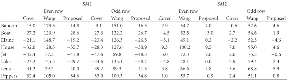
Table5: Histogram-based attacks can be performed separately on the odd and even rows. The values of the proposed method are similar to the cover while those of the Wang et al.’s method are very higher than the cover.
SM1 SM2
Even row Odd row Even row Odd row
Cover Wang Proposed Cover Wang Proposed Cover Wang Proposed Cover Wang Proposed
Baboon −15.0 173.5 −14.8 −9.1 151.0 −16.3 2.9 54.7 4.0 −0.6 52.6 4.6
Boat −27.2 123.9 −28.6 −27.3 122.2 −26.7 −4.5 52.5 −3.0 2.7 54.6 1.9
Elaine −21.1 148.7 −19.2 −23.4 126.3 −26.5 −3.1 49.1 0.2 −2.2 52.5 −4.6
House −32.6 128.3 −35.7 −28.3 127.6 −30.9 9.3 100.2 9.5 7.6 95.0 4.6
Jet −42.4 77.3 −41.8 −47.6 69.8 −48.3 3.0 72.3 2.6 2.6 75.3 −0.6
Lake −23.2 125.3 −29.7 −24.6 135.1 −28.7 −4.8 48.1 0.0 2.9 59.4 2.3
Lena −41.2 79.2 −40.0 −39.2 89.3 −41.5 3.8 66.6 4.8 5.6 68.8 5.9
Peppers −32.4 105.0 −34.6 −33.0 109.3 −34.6 1.0 53.7 −0.9 2.4 51.1 0.8
Table6: Comparison of hiding capacity (bytes) and visual quality (dB).
Wu [9] Zhang [10] Wang [14] Yang [16] Proposed
Lmax PSNR Lmax PSNR Lmax PSNR Lmax PSNR Lmax PSNR
Baboon 57,028 37.0 53,586 40.4 57,043 40.2 80,688 39.6 57,043 39.2
Boat 52,320 39.6 50,926 42.4 52,490 41.1 71,788 42.1 52,490 41.0
Elaine 50,891 42.1 49,750 44.5 50,893 44.9 68,994 43.6 50,893 43.5
House 52,418 40.0 51,003 42.7 52,572 42.4 72,043 42.0 52,572 41.5
Jet 51,221 40.6 50,366 43.5 51,221 43.4 69,415 42.9 51,221 42.8
Lake 52,614 40.0 50,970 42.7 52,662 42.4 72,304 41.9 52,662 41.5
Lena 50,894 41.5 50,023 44.3 50,894 43.4 68,927 43.3 50,894 43.4
Peppers 50,657 41.5 49,968 43.9 50,815 43.4 68,632 43.4 50,815 42.5
10 20 30 40 50 60 70 80 90 100 Image number
0.7 0.75 0.8 0.85 0.9 0.95 1 1.05 1.1
Det
ect
or
val
u
e
Cover LSB matching
Yang et al.’s Proposed
Figure6: HCF-COM ratio of the full-sized images to the downsam-pled images for the cover images, obtained using the LSB matching, the Yang et al.’s, and the proposed method.
C(H[k]) = n
i=0i|H[i]|/
n
i=0|H[i]|. This parameter gives general information about the energy distribution in the HCF. The discriminator used to differentiate stego images from cover images isC(H[k])/C(H[k]).Figure 6plots the detector values of the HCF-COM ratios for 100 randomly selected natural images from the NRCS image database [21]
that satisfyC(H[k])≈C(H[k]). The discriminator values of the stego images obtained using the proposed method were close to 1, similar to the cover images, while the values of the stego images obtained using the LSB matching method and the Yang et al.’s method were, on average, 0.76 and 0.80, respectively. This means that the proposed method is secure against calibrated HCF-COM attack of steganalysis for LSB matching.
4.4. Security Analysis under the PVD Histogram-Based Attacks. Zhang and Wang insisted that the steps at [7 8], [15 16], [31 64], and [127 128] in the PVD histograms clearly revealed the presence of the hidden message [10]. This assertion was based on the step effects generated by the embedding process used in Wu and Tsai’s method. However, since our proposed method produces no step effects and the PVD histogram after embedding is very similar to the cover, as inFigure 4, it is impossible to detect the existence of the hidden message using Zhang and Wang’s analysis.
Baboon Boat House Lake Lena
−40
−20
0 20 40 60 80 100 120 140 160 180
Cover Wang et al.’s Proposed
(a)SM1
Baboon Boat House Lake Lena 0
20 40 60 80 100 120
Cover Wang et al.’s Proposed
(b)SM2
Baboon Boat House Lake Lena
−10
0 10 20 30 40 50 60
Cover Wang et al.’s Proposed
(c)SM3 Figure7: Three steganalytic measures of the cover, using Wang et al.’s and our proposed method.
removes all the weaknesses of Wang et al.’s method and is secure under PVD histogram-based attacks.
The histogram-based attack can be performed separately on the odd rows and even rows of the stego images. Because of the permutation of the sub-blocks in the first pixel pairing step of the proposed method, theSM1 andSM2 values of the stego image produced by the proposed scheme were similar to those of the cover image as shown in Table 5. Consequently, the proposed method is secure under the separate attack of the steganalytic measures described in
Section 2.2.
4.5. Hiding Capacity and Perceptual Quality Analysis. As previously mentioned, effective steganography must possess high embedding capacity and good imperceptibility to the naked eye. Table 6 presents the maximum capacity (Lmax) and PSNR values for the PVD steganographic methods discussed herein. Although the PSNR values of our proposed method were slightly lower than those of Wang et al.’s method for the same capacity, our method nevertheless provides a good image quality for the human visual system because the human eye cannot see the decline in quality of stego images when PSNR values are over 38 dB [22]. In other words, a slightly lower PSNR than Wang et al.’s method is almost insignificant in terms of quality. Both Zhang and Wang’s and Wang et al.’s method had already defeated, despite the high PSNR values. Even though Yang et al.’s method can provide the high capacity and good image quality, it is vulnerable under the LSB steganalysis such as RS-analysis (seeFigure 5) and Ker’s calibrated HCF-COM attack (seeFigure 6). However, our proposed method achieved the
high hiding capacity and security compared with the other PVD steganographic methods by sacrificing only a little visual quality.
5. Conclusion
List of Symbols
α: Embedding rate
β: Pseudo-random parameter
d: Difference between two pixels of the sub-block
h: PVD histogram of the cover image h: PVD histogram of the stego image he: Estimated PVD histogram of the
suspicious image
i: Selecting sequence of the sub-blocks k: Index of the range tableR
lkv Lower bound of the subrangeRk
m: Modifying value to embed the message ti: Length of embedding bits
ti: Decimal value oftimessage bits
uk: Upper bound of the subrangeRk
wk: Width of the subrangeRk
z: Overcoming value to solve the falling-off-boundary problem
C(H[k]): Center Of Mass (COM) of the HCF of the full-sized image.
C(H[k]): Center Of Mass (COM) of the HCF of the down-sampled image
DF: Discrimination function of the RS-steganalysis
F: Cover image
Fi: ith sub-block of the cover image
Frem(i): Remainder value ofFi
H[k]: Histogram Characteristic Function (HCF)
Lmax: Maximum embedding capacity M: Flipping mask
(P(i,x),P(i,y)): Two pixels ofFiin the cover image
(P(i,x),P(i,y)): New stego pixel values ofFi
R: Range table
RM: Proportion of blocks with increasing
magnitude ofDFunderM
R−M: Proportion of blocks with increasing
magnitude ofDFunder –M S: Secret data to be embedded
SM: Proportion of blocks with decreasing
magnitude ofDFunderM
S−M: Proportion of blocks with decreasing
magnitude ofDFunder –M
Acknowledgment
This research was supported by NRL (National Research Lab) program through the National Research Founda-tion of Korea funded by the Ministry of EducaFounda-tion, Sci-ence and Technology (no. R0A-2007-000-20023-0), and by Ministry of Culture, Sports and Tourism (MCST) and Korea Culture Content Agency (KOCCA) in the Cul-ture Technology (CT) Research & Developement Program 2009.
References
[1] Z. Chen and W. Liu, “Improved LSB matching steganography with histogram characters reserved,” inInformation Optics and Photonics Technologies II, vol. 6837 ofProceedings of SPIE, p. 68370X, Beijing, China, November 2007.
[2] K. Solanki, A. Sarkar, and B. S. Manjunath, “YASS: yet another steganographic scheme that resists blind steganalysis,” inProceedings of the 9th International Workshop on Information Hiding (IH ’07), vol. 4567 ofLecture Notes in Computer Science, pp. 16–31, 2007.
[3] P. K. Amin, N. Liu, and K. P. Subbalakshmi, “Statistical attack resilient data hiding,”International Journal of Network Security, vol. 5, no. 3, pp. 112–120, 2007.
[4] J. Fridrich and M. Goljan, “Practical steganalysis of digital images—state of the art,” in Security and Watermarking of Multimedia Contents IV, vol. 4675 ofProceedings of SPIE, pp. 1–13, San Jose, Calif, USA, January 2002.
[5] A. D. Ker, “Steganalysis of LSB matching in grayscale images,”
IEEE Signal Processing Letters, vol. 12, no. 6, pp. 441–444, 2005. [6] J. J. Harmsen and W. A. Pearlman, “Steganalysis of additive noise modelable information hiding,” inSecurity and Water-marking of Multimedia Contents V, vol. 5020 ofProceedings of SPIE, pp. 131–142, 2003.
[7] S. Lyu and H. Farid, “Steganalysis using higher-order image statistics,” IEEE Transactions on Information Forensics and Security, vol. 1, no. 1, pp. 111–119, 2006.
[8] I. Avcibas¸, M. Kharrazi, N. Memon, and B. Sankur, “Image ste-ganalysis with binary similarity measures,”EURASIP Journal on Applied Signal Processing, vol. 2005, no. 17, pp. 2749–2757, 2005.
[9] D.-C. Wu and W.-H. Tsai, “A steganographic method for images by pixel-value differencing,”Pattern Recognition Let-ters, vol. 24, no. 9-10, pp. 1613–1626, 2003.
[10] X. Zhang and S. Wang, “Vulnerability of pixel-value diff erenc-ing steganography to histogram analysis and modification for enhanced security,”Pattern Recognition Letters, vol. 25, no. 3, pp. 331–339, 2004.
[11] V. Sabeti, S. Samavi, M. Mahdavi, and S. Shirani, “Steganalysis and payload estimation of embedding in pixel differences using neural networks,”Pattern Recognition, vol. 43, no. 1, pp. 405–415, 2010.
[12] H.-C. Wu, N.-I. Wu, C.-S. Tsai, and M.-S. Hwang, “Image steganographic scheme based on pixel-value differencing and LSB replacement methods,”IEE Proceedings: Vision, Image and Signal Processing, vol. 152, no. 5, pp. 611–615, 2005.
[13] V. Sabeti, S. Samavi, M. Mahdavi, and S. Shirani, “Steganalysis of pixel-value differencing steganographic method,” in Pro-ceedings of IEEE Pacific RIM Conference on Communications, Computers, and Signal Processing, pp. 292–295, 2007. [14] C.-M. Wang, N.-I. Wu, C.-S. Tsai, and M.-S. Hwang, “A high
quality steganographic method with pixel-value differencing and modulus function,”Journal of Systems and Software, vol. 81, no. 1, pp. 150–158, 2008.
[15] J.-C. Joo, H.-Y. Lee, C. N. Bui, W.-Y. Yoo, and H.-K. Lee, “Steganalytic measures for the steganography using pixel-value differencing and modulus function,” inProceedings of the 9th Pacific Rim Conference on Multimedia, vol. 5353 ofLecture Notes in Computer Science, pp. 476–485, 2008.
[17] C.-C. Thien and J.-C. Lin, “A simple and high-hiding capacity method for hiding digit-by-digit data in images based on modulus function,”Pattern Recognition, vol. 36, no. 12, pp. 2875–2881, 2003.
[18] S.-J. Wang, “Steganography of capacity required using modulo operator for embedding secret image,”Applied Mathematics and Computation, vol. 164, no. 1, pp. 99–116, 2005.
[19] T. Zhang and X. Ping, “A new approach to reliable detection of LSB steganography in natural images,”Signal Processing, vol. 83, no. 10, pp. 2085–2093, 2003.
[20] S. Walton, “Information authentication for a slippery new age,”Dr. Dobbs Journal, vol. 20, no. 4, pp. 18–26, 1995. [21] “NRCS Photo Gallery Home,” http://photogallery.nrcs.usda
.gov/.