A Image Steganography Method with Five Pixel Pair
Differencing and Modulus Function
Gulve Avinash K
Government College of Engineering, Aurangabad
Joshi M.S.
Prof. & Head, Computer Engineering Department MIT College of Engineering,
Pune
ABSTRACT
In this paper, a new image steganography algorithm is proposed which provides better stego-image quality. For hiding the secret data, PVD approach is used. The hiding capacity depends on the difference in pixel values. If the pixels in the pair belong to smooth area, difference is less and if the pixels belong to an edge, difference is very large. If the difference value is large, more data can be hidden. But hiding more data can cause distortion in the stego-image. The algorithm uses modulus function to revise the difference so that it will always be in the range 0 difference 15. This enables us to hide maximum 3 bits in a pixel pair causing less distortion in the stego image. The difference value is revised before being used for estimating number of bits that can be hidden in each pair. This makes detection of exact secret message harder for the steganalyst. Thus an extra layer of security is introduced.
General terms- Steganography, Information Security
Keywords: data hiding, steganography, cover image, stego image, modulus function
1. Introduction
Nowadays, due to a dense development of the modern technology of computer and communication, message transmission is rapid and convenient. To protect secret message from being stolen during transmission, steganography techniques are widely used. Steganography involves hiding information so that it appears that no information is hidden at all. The message can be hidden in images, audio files [1] or in text [2][3].
.Image steganography is about exploiting the limited powers of the human visual system (HVS). Any plain text, cipher text, other mages, or anything that can be converted in a bit stream, can be hidden in an image. A digital image is composed of finite number of elements each of which has a particular location and value (gray scale). The message in encrypted form or in the original form is embedded as the secret message to be sent into a image. The image created after embedding secret data, is called a stego-image. Additional secret data may be needed in the hiding process e.g. a stegokey. The stego-image is then transmitted to the recipient. The recipient extracts the message from the carrier image [4].
Among all the image information hiding methods, LSB embedding is widely used for its high hiding capacity, and simplicity to realize. Based on number of LSB’s used for hiding the information, LSB based image steganography methods are classified as 1 bit stego, 2 bit stego, 3 bit stego and 4 bit stego [4].
2. Review of PVD based
methods
In the PVD method proposed by Wu and Tsai, the original cover image is partitioned into non-overlapping blocks of two consecutive pixels. Thus a pixel pair is available in every block. The difference between pixel values of both the pixels in the pair is calculated. Based on the characteristics of human vision’s sensitivity to gray value variations from smoothness to contrast, all possible difference values are classified into a number of ranges. The number of secret bits that can be embedded in the pixel pair are directly proportionate to the width of the range. After embedding a sub stream of secret message in the pair, a new difference value is obtained. The pixel values are then adjusted so that the new difference value can stand for the secret data [5][6].
To improve the capacity and quality of image another enhanced method is introduced based on the PVD method by Ko-Chin Chang et al. In this method data can be hidden in vertical and diagonal edges along with the horizontal edges. The cover image is divided into non-overlapping blocks of 2 x 2 pixels. Each 2 x 2 block includes four pixels of P(x,y) ,
P(x+1,y), P(x,y+1) and P(x+1,y+1), where x, and y are the pixel
locations in the image. Let P(x,y) be the starting point, then
three pixel pairs can be formed by grouping P(x,y), with the
right, the lower, and the lower right neighbouring pixels. Those three pairs are named by P0, P1 and P2 where P0 = (P(x,y),P(x+1,y)), P1 = (P(x,y),P(x,y+1)) and P2 = (P(x,y),P(x+1,y+1) ),
respectively. Secret data is hidden in the three pairs using PVD approach. Pixel P(x,y) is common in all three pairs. So
three different values are obtained for P(x,y). So one of the
three pairs is selected as reference pair and used to adjust values of other pixels in the block [7][8].
Naznin Zaker et al. has proposed some modifications to PVD method to make it more robust to histogram quantization [9]. 1. For the difference d ε Ri , the maximum number of secret
bits are selected to let new difference, d’, satisfy the condition |d’| ≤ |d|.
2. A slight overlap in boundaries of applied set of ranges is made.
The algorithm prevents the “grouping effect” that results in histogram quantization and increases the security of the hidden data [9].
Min-Yen Chiu et. al. has proposed a method in which the secret data is separated in two parts and the range table into lower and higher level. Based on the difference value, the secret data is concealed in the block [11].
Asmari And Ghamdi proposed a steganography method based on pixel value differencing and LSB substitution. The cover image is divided into sub-blocks of 4 x 4 pixels each. The data is hidden in two consecutive pixels vertically depending on the pixel value difference with three least significant bits method. The embedding process begins with hiding 3 LSB in each pixel at corner. So that 12 bits are directly hidden in the 4 pixels at corner with LSB substitution method. Then remaining 12 pixels form the semi hexagonal shape. The embedding of data is applied on two consecutive pixels vertically. The embedding process determines the range for each pair. If the range is higher, then PVD method is used for hiding the data. Otherwise 3 bits are directly hidden in each pixel of the pair. This method offers higher capacity for data hiding and produces stego images of good quality [12]
3. The proposed algorithm -
The key idea of this algorithm is to cause minimal embedding distortion of the cover image. The proposed algorithm uses pixel value difference to embed the secret data. The PVD approach embeds the data in pixel pair using the difference value between the pixels in that pair. The difference value is mapped with the range table. The number of bits to be hidden in the pair depends upon the width of the selected range.
As shown in Figure 1, each 2 x 3 block includes six pixels P(x,y) , P(x,y+1), P(x,y+2), P(x+1,y), P(x+1,y+1) and P(x+1,y+2)
[image:2.595.93.240.426.507.2]where x and y are the pixel locations in the image.
Fig 1 Pixel Block
Let P(x+1,y) be the starting point, then five pixel pairs
can be formed as
P1 = (P(x,y),P(x,y+1) ),
P2 = (P(x,y+2),P(x,y+1) ),
P3 = (P(x+1,y),P(x,y+1) ),
P4 = (P(x+1,y+1),P(x,y+1) )
P5 = (P(x+1,y+2),P(x,y+1) ).
The difference value di is calculated for each pixel
pair Pi. This difference value is used to identify the range Ri,k
from the range table R. The range table is designed with ranges [0,3], [4-7], [8-15]. The width Wi,k = ui,k-li,k+1, of
range Ri,k is used to determine the number of bits ti (ti = |
log2Wi,k |) that can be hidden in each pair. After embedding ti
bits of the message in the pixel pair, new difference d’is calculated as li,k+b where li,k represents lower boundary of the
range Ri,k in the range table R and b represents the decimal
equivalent of message bits hidden in that pair. The m value, given by d’i – di , is used to determine new values of pixels in
the pair. The pixel p(x,y+1) participates with other five pixels to
form five pairs in the block. So five different values are obtained for the pixel p(x,y+1). The pixels values of the pair
with minimum |m| are very close to original values because of small value of the difference between d’i and di. This pixel
pair is used as reference pair to determine values of other pixels in the block.
The difference between d’i and di is very large if b
is very small as compared to the width wi of the range Ri (i.e.
b is close to 0). This may cause distortion in the stego image. It is, therefore, necessary that d’i di to obtain best quality of
stego-images. If di is kept very small, d’i will also be very
small since d’i and di are always in the same range. di can be
kept very small by revising its value using modulus operator. The proposed algorithm revises the difference di so that it is
always less than 15. Since di is in the range 0 di 15, d’i
will also be in the same range,
The details of data hiding steps are described below. The TPVD method suggested by Chang [7][8] is extended and modified in the proposed method so that it improves the quality and security of the stego image.
1. Partition the stego-image into 2 x 3 pixel blocks. 2. Calculate the difference values di for the five pixel pairs
in each block given by
d0 = P(x,y) - P(x,y+1)
d1 = P(x,y+2) - P(x,y+1)
d2 = P(x+1,y) - P(x,y+1)
d3 = P(x+1,y+1) - P(x,y+1)
d4 = P(x+1,y+2) - P(x,y+1)
3. Find the revised difference d1i where i = 0,1,2,3,4 as
d1i = remainder(di/16)
4. Use | d1i | where i = 0,1,2,3,4 to locate suitable range Ri,k
in the designed range table. The ranges in the range tables are used as (0,3), (4,7), (8,15).
5. Compute the amount of secrete bits ti that can be
embedded in each pair using the corresponding range given by Ri,k. The value ti can be estimated from the
width wi,k of Ri,k , which is obtained as ti = | log2wi,k |
where width wi,k = ui,k-li,k+1 and ui,k and li,k are upper and
lower boundaries of the range Ri,k.
6. Read ti bits from the binary secret data and transform the
bit sequence into a decimal value bi.
7. Calculate the new difference value d’i given by
d’i = (|di |– |d1i|)+li,k +bi, if di ≥ 0
d’i = -(|di |– |d1i|)+li,k +bi ), if di < 0
to replace the original difference di.
8. Modify the values of pixels in P’i by using the following
equation
(P’n , P’n+1) = ( Pn - | m/2 |, Pn+1 + | m/2 | ) where Pn
and Pn+1 represents two pixels in the pair Pi and m is
the difference between di and d’i. This is given by m= d’i
– di.
9. Use the pair with minimum | m| as the optimal reference pair P’i , then this selected pair is used to offset the other
four pixel pairs. Thus new values are calculated for all the six pixels in the block.
to 255. If not, modify the pixel values preserving the difference between pairs
a. Find out smallest of all the pixel values. If smallest is less than 0 then add |smallest| with all the pixel values in that block.
b. Find out largest of all the pixel values. If largest is greater than 255, subtract largest-255 from all the pixel values in that block.
c. If fall of boundary problem still persists, then the cover image is not suitable for hiding secret data. 11. Now, construct the new block from all pixel pairs with
modified pixel values.
12. Repeat steps 1 trough 11 till the message gets embedded in the cover image.
The embedding procedure is explained in fig. 2. Following algorithm describes how to retrieve the embedded secret data from the stego-image.
1. Partition the stego-image into 2 x 3 pixel blocks, and keep the partition order same as embedding stage. 2. Calculate in difference values separately for each block
in the stego-image given by d0 = P(x,y) - P(x,y+1)
d1 = P(x,y+2) - P(x,y+1)
d2 = P(x+1,y) - P(x,y+1)
d3 = P(x+1,y+1) - P(x,y+1)
d4 = P(x+1,y+2) - P(x,y+1)
3. Find the revised difference d1’i where i = 0,1,2,3,4 as
d1’i = remainder(d’i/16)
4. Use | d1’i | where i = 0,1,2,3,4 to locate suitable Ri,k in
the designed range table
5. After Ri,k is located, li,k is subtracted from the selected
|d1’i| and b’i is obtained in the decimal form. b’i is
converted into a binary sequence with ti bits where ti =
|log2wi,k |.
6. Repeat steps 1 through 5 till embedded message is extracted.
The extraction procedure is explained in fig. 3.
4. Implementation Results
The purpose of the proposed algorithms is to enhance the quality of stego image so that the stego-images will be perceptually similar to the original cover image.
The proposed algorithm uses the remainder of the difference value of the pixels in the pixel pair to hide the data. This reduces the hiding capacity but increases the quality of the stego image. There is a trade off between hiding capacity and quality of stego image. As hiding capacity increases, quality of stego image degrades. Thus sacrificing a small amount of hiding capacity, the secret data can be securely hidden.
A text file of size 58.1Kb (59538 Bytes) is used for experimentation. This text file is used as secret message, which is to be hidden in the cover image. The two methods are tested for various cover images. TIFF images are used as cover images.
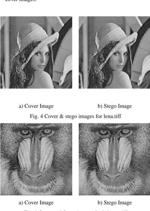
a) Cover Image b) Stego Image Fig. 4 Cover & stego images for lena.tiff
[image:3.595.306.547.120.457.2]a) Cover Image b) Stego Image Fig. 5 Cover and Stego images for baboon.tiff
Fig. 4 and fig. 5 shows the cover image and stego images obtained using the proposed method.
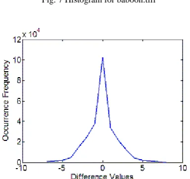
Fig. 6 and fig. 7 shows the histogram of the cover and stego image obtained using the proposed method. The stego images are created from cover images utilizing the maximum data hiding capacity. It can be observed that the shape of the histogram is preserved after embedding the secret data.
[image:3.595.317.542.599.701.2]a) Cover Image b) Stego Image Fig. 7 Histogram for baboon.tiff
Fig. 8 Histogram Difference for lena.tiff
The revised difference d1i and the new difference
d’i are always in the range [0-15]. This ensures that the
histogram difference will also be in the same range. Fig. 8 shows the histogram difference. The difference is very small. From the figure, it is observed that, bins close to zero, are more in number and the bins, which are away from zero, are less in number. This confirms the quality of stego-image. Since step pattern is not observed in fig.8, the proposed method is robust against histogram analysis.
Histogram of cover image is represented as [ho,h1,…,h255] whereas histogram of stego-image is
represented as [h’o,h’1,…,h’255]. The change is histogram can
be measured by [13]
255
1
| '
|
h m m
m
D
h
h
Fig. 9 is drawn for lena.tiff which compares the value of Dh of the 3 bit LSB replacement method and the
proposed method with various embedding sizes. It can be observed that the change in histogram difference Dh is very
small for the proposed method even if full capacity of cover image is utilized for embedding secret data.
Fig. 9 Comparison of 3 bit LSB substitution method with proposed method
0.2 0.22 0.24 0.26 0.280.3 0.32 0.34
1 2 3 4 5 6
Message size in Kb
R
a
tio
of
R
,S RM
R-M
SM
S-M
Fig.10 RS Steganalysis
The output images (for lenna.tiff) are tested under the RS steganalysis [14]. It is observed from fig. 10 that the values of RM and R-M, SM and S-M are nearly equal. Thus rule
RM R-M and SM S-M is satisfied for the output images. So
the proposed method is secure against RS attack.
PSNR computes the peak signal-to-noise ratio, in decibels, for the two images. This ratio is often used as a quality measure between the original and the stego image. The higher the PSNR, the better is the quality of the reconstructed image. PSNR is given by PSNR = 10*log10(255*255/MSE).
Table 1 shows the comparison of hiding capacity and PSNR of proposed method with other methods. It can be observed that proposed method provides 14% - 17% increase in hiding capacity with PSNR values above 44 which is well above the threshold of 36 dB [15].
Table 2 PSNR values Cover
Image
Capacity In Kb
PSNR MSE Q
[image:4.595.66.259.184.365.2] [image:4.595.319.545.275.396.2]Table 2 shows the hiding capacity and PSNR values for different images obtained using the proposed method after embedding a secret message file of 58Kb. Also Universal Quality Index (Q) is used to measure the quality of stego-image [16]. Q values are close to 1, which confirms that the stego images are of good quality.
The results show that the proposed algorithm provides promising performance in increasing the capacity of the stego-images and maintaining the imperceptible quality simultaneously.
5. Conclusion and future scope
It is obvious that the stego image should be acceptable so that the human eye cannot identify the embedded data from the stego image. Also, the scheme should offer high payload so that more secret information could be embedded with high imperceptibility. But there is a trade-off between hiding capacity and quality of stego image. As the data hiding capacity increases, the quality of the stego image degrades.
Instead of using the difference value directly, the proposed algorithm modifies it before hiding the data. This introduces an extra layer of security since the secret data cannot be extracted directly using the difference value. This proposed algorithm increases the quality of the stego image, which is proven by the results. Although capacity of data hiding is some what scarified for maintaining the quality of the stego image, still it is acceptable. The algorithm divides the cover image into block of 2 x 3. This helps in forming more number of pixel pairs, which provides more space for data hiding. The secret data hidden in the stego image can be extracted correctly without the participation of original cover images.
In the above algorithms P0 is used as the starting
pixel. Instead the algorithm can be modified to properly select the starting pixel. This will allow selection of any of the six pixels to be used as starting pixel to ensure less distortion in the stego image and increase in the security.
6. References
[1] Samir K Bandyopadhyay, Debnath Bhattacharyya, Debashis Ganguly, Swarnendu Mukherjee and Poulami Das, Aug 7-9, 2008, A Tutorial Review on Steganography, International conference on contemporary computing, JIIT, Nioda, India
[2] Zunera Jalil and Anwar M. Mirza ,2009, A Review of Digital Watermarking Techniques for Text Documents, International Conference on Information and Multimedia Technology
[3] S. Changder ,N.C. Debnath, ,D. Ghosh,2009, A New Approach to Hindi Text Steganography by Shifting Matra, International Conference on Advances in Recent Technologies in Communication and Computing [4] P. Mohan Kumar and K. L. Shanmuganathan,2011
Developing a Secure Image Steganographic System Using TPVD Adaptive LSB Matching Revisited
Algorithm for Maximizing the Embedding Rate, Journal of Telecommunications and Information Technology [5] Da-Chun Wu , Wen-Hsiang Tsai, 2003, A
steganographic method for images by pixel-value differencing, ELSEVIER Pattern Recognition Letters, p.p. 1613–1626
[6] H.-C. Wu, N.-I. Wu, C.-S. Tsai, and M.-S. Hwang, ,2005, Image steganographic scheme based on pixel-value differencing and LSB replacement methods, IEE Proceedings on Vision, Image and Signal Processing, Vol. 152, No. 5, pp. 611-615.
[7] Ko-Chin Chang, Ping S. Huang, Te-Ming Tu, and Chien-Ping Chang, 2007, Adaptive Image Steganographic Scheme Based on Tri-way Pixel-Value Differencing, IEEE International conference on Systems, Man and Cybernetics, pp. 1165-1168.
[8] Ko-Chin Chang, Chien-Ping Chang, Ping S. Huang, and Te-Ming Tu, 2008, A Novel Image Steganographic Method Using Tri-way Pixel-Value Differencing, JOURNAL OF MULTIMEDIA, VOL. 3, NO. 2, pp. 37-44,
[9] Nazanin Zaker, Ali Hamzeh, Seraj Dean Katebi, Shadrokh Samavi , 2009, Improving Security of Pixel Value Differencing Steganographic Method, 3Rd IEEE International conference on New Technologies, Mobility and Security (NTMS), pp.1-4
[10] Chung-Ming Wang, Nan-I Wu, Chwei-Shyong Tsai, Min-Shiang Hwang,2007, A high quality steganographic method with pixel-value differencing and modulus function, The Journal of Systems and Software
[11] Min-Yen Chiu, Yu-Sheng Liao, Jiun-Jian Liaw, ,2010, Improved Steganographic Technique for the Image Quality of PVD, International Conference on Advanced Information Technologies (AIT)
[12] Asmari, Ghamdi, 2009, High Capacity Data Hiding Using Semi-Hexagonal Pixels Value Difference, International Conference on High Performance Computing, Networking and Communication Systems (HPCNCS-09), Orlando, Florida, USA, pp. 14-17 [13] Xinpeng Zhang, Shuozhong Wang, February, 2012,
Efficient data hiding with histogram-preserving property, Telecommunication Systems, Volume 49- 2, p.p.179-185 [14] J. Fridrich, M. Goljan, and R. Du, 2001, Detecting LSB steganography in color, and gray-scale images, IEEE Multimedia, vol. 8, no. 4, pp. 22–28
[15] Wu, Hwang, 2007, Data Hiding: Current Status and Key Issues, International Journal of Network Security, vol. 4, no. 1, pp. 1-9
Table 1 Comparison between various techniques
Wang’s Method [10] Min-Yen Chiu’s method [11] Proposed Method
Capacity PSNR Capacity PSNR Capacity PSNR
Lena 51219 44.1 51223 48.42 59643 46.11
Baboon 57146 40.3 57138 46.09 65019 44.79
Peppers 50907 43.3 50909 48.48 60009 45.93
Fig. 2 Embedding Process
100
126
112
115
107
120
26
12
15
7
20
0
3
4
7
8
15
32
63
8+6=14
Bit Stream- 110 101 010 01 11
8+5=13
8+2=10
4+1=5
4+3=7
4
1
-5
-2
3
P0 = (98,128)
P1 = (99,112)
P2 = (103, 113)
P3 = (101, 106)
P4 = (100,121)
[(98+99-98),(128+99-98)]
[99,112]
[(103+99-103),(113+99-103)]
[(101+99-101),(106+99-101)]
[(98+99-98), (121+99-98)]
99
129
112
109
104
122
(P
’i, P
’i+1
) = (P
i– ceil(M/2) ,
P
i+1+floor(M/2)
10
12
15
7
4
16
0
0
0
16
30
13
10
5
23
Pixel block d d1 Range Table Offset Diff d’ M
Figure 3 Extraction Process
![Table 1 Comparison between various techniques Wang’s Method [10]](https://thumb-us.123doks.com/thumbv2/123dok_us/8078706.781659/6.595.29.578.99.642/table-comparison-various-techniques-wang-s-method.webp)

