The caustics method in the contact problems of anisotropic
materials
A. Baki1, a, D. Semenski1, and S. Jeci1
1
Faculty of Mechanical Engineering and Naval Architecture, Ivana Luia 5, 10 000 Zagreb, Croatia
Abstract. Regions with high stress gradients represent critical zones of engineering structures such as crack tip or vicinity of the contact zone. The optical method of caustics is one of the few experimental methods which provide applicable results in these locations. This method was originally developed for crack-tip measurements of stress intensity factors and J-integral for isotropic and then for anisotropic materials. Subsequently, it was extended to contact problems where the size and shape of caustics on the screen are related to the amount and the inclination of loading force. Here, the method of caustics is extended to the analysis of contact problems for mechanically anisotropic materials. This makes the caustics method widely applicable to the analysis of any high stress gradient locations in a structure.
1 Introduction
Comparison of the simulations of the optical effect and the experiments indicated that for the anisotropic materials size and shape of caustic curve not only depend on the loading condition but also on the mechanical material properties. In isotropic materials the shape of the caustics curve is unique for all materials and can be expressed by the epicycloids equation [1], [2].
Because of the applied contact force, surfaces of the model are deformed to a convex shape and the reflected light is not homogenous any more; instead, a dark spot surrounded by the concentrated light on its edge (caustics) can be seen on the screen. When non-transparent materials are concerned, it is possible to record caustics only by utilizing the light reflected from the model surface. On the other hand, when transparent materials are concerned, caustics can be formed by the reflecting light from both the front and the rear surface of a model. Since the screen is in front of the model, only a virtual image is obtained. It can be converted into a real image by transferring the light through the focus of a convex lens.
A plate loaded by cylindrical punch is considered as material model. The illustrative examples for two materials will be shown. A referent isotropic material is Araldit B (E= 3,48 GPa, = 0.38) and as anisotropic material uniaxial carbon fibre-reinforced (CFRP131) is used (EL= 131 GPa, ET=EB= 12 GPa, GLT=18 GPa, LT= 0.29, TL= 0.29, TB= 0.34). Uniaxial carbon fibre-reinforced
materials are extremely orthotropic materials which is interesting for analyzing how orthotropy affect on shape of caustics. Another benefit of such material is small diameter of fibres (up to 10 m)
a
e-mail: [email protected]
© Owned by the authors, published by EDP Sciences, 2010 DOI:10.1051/epjconf/20100611003
which makes it applicable for macro-mechanical analysis. Dimensions of the plate specimen are 50x50x3 mm and they are same for both materials.
2 Analytical approach
For an analytical approach of the optical effect it is necessary to connect model deformations with the load condition. Lekhnitskii [3], among others, provided an explicit solution to this problem for anisotropic materials by using a complex variable under the following assumptions: the material is of linear elastic characteristics, from a macro-mechanical point of view the material is a homogeneous continuum and the model is in a state of plane stress.
These conditions are satisfied for a thin plate of material with general rectilinear anisotropy and one plane of elastic symmetry (x-y plane). Therefore, the compliance material matrix, Sij, consist 13 nonzero elastic constants.
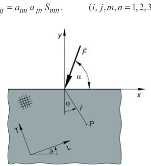
2.1 Stress state in the anisotropic plate loaded by the contact force
The contact problem is described as the action of a force F inclined by the angle on the anisotropic semi-infinite plane (Figure 1). The complex variable is zk x Pky, where Pkare the roots of the characteristic equation
2 2 02 16 3 12 66 2 26 22
4
11 S S S S S
S Pk Pk Pk Pk
.
(1)1 1 1 1 3 1
2 2 2 2 4 2
i ( 0), ,
i ( 0), .
P D E E P P
P D E E P P
!
!
.
(2)They contain information about the mechanical characteristics of the material in the in x and y direction. If the principal axes of orthotropy are arbitrarily rotated regarding to x-y coordinates corresponding coefficients Smn should be recalculated before applying to the characteristic equation
. ( , , , 1, 2, 3, 6)
ij im jn mn
S a a S i j m n (3)
Fig. 1. An anisotropic semi-infinite plane loaded by concentrated force The stress state can be derived in the following form
>
@
11 ( sin cos ) sin (( ) sin cos ) cos , ( )
0 r
r FS
a b a
r L
M M
V M M D E G M M D
S M
V V
where,
4 3 2 2
11 16 12 66
3 4
26 22
( ) cos 2 sin cos (2 ) sin cos
2 sin cos sin ,
L S S S S
S S
M M M M M M
M M M
(5)
1 2 2 1E D E
D
a (6)
D12E12E2D22E22E1b (7)
Transversal deformation for the stress state is derived from Hooks low
xy y
x
z S V S V S W
H 31 32 36
.
(8)Although all these equation are valuable for general rectilinear anisotropy analytical solution of the caustic curve will be carried out for orthotropic materials. Materials at our disposal are mainly of orthotropic structure and it is possible to find the principal axes of orthotropy: L-longitudinal, T-transversal and B-biT-transversal, which is directed across the plate thickness.
2.2 Theory of caustics
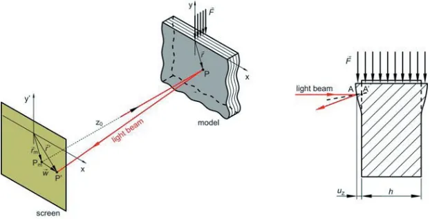
The explanation of the reflection method of caustics to the non-transparent materials starts from the basic principle of the optical low of reflection. The specimen is loaded and illuminated by the concentrated field of light in the zone of high deformation gradients. The light beams are reflected and transferred from the specimen surface to the virtual plane at distance z0. The result on the screen
is a dark spot, surrounded by the concentrated light on its edge. The position of single light at the point P’(x’,y’) on the screen is defined by the vector 'rG , and its corresponding point P(x,y) on the model is defined by the vector rG (Figure 2).
Fig. 2. Geometrical princip of the beam deflection in the reflecting optical setup. The vectors are related by equations
0 ' m
r r w mrz grad s'
G G G G
,
(9)
Retardation of the reflected light beam for non-transparent materials is given by a simple equation (Figure 2)
z
z x y h
u AA s s
s H
' ' 2 ' 2 ( , )
.
(10)where s is optical path of light beam for unloaded and s’ is optical path for loaded specimen. So, formula (9) becomes
z
m w mr z hgrad
r
rG' G 0 H
,
(11)where M M H H H e r e
grad z z,rGr1 z, G
.
(12)Finally the position of the light beam on the screen is
¸ ¹ · ¨ © §
H M H M
M sin 1 Mcos
sin
' 0 z,r z,
r h
z mr
x
,
(13)¸ ¹ · ¨ © §
sinM H cosM 1H MsinM
' 0 z,r z,
r h
z mr
y
.
(14)2.3 Singular caustic curve and initial curve
The singular caustic curve is a strongly illuminated edge surrounding dark spot. The condition of existence of the singularity is the zeroing of the Jacobian determinant
, , , ,
( ', ')
' ' ' ' 0
( , ) r r
x y
J x y x y
rM M M
w
w
.
(15)This function represents the position of the initial curve on the specimen, from which the light beams are reflected and projected onto the singular caustic curve. In order to show the solution equation the following function are introduced
2 2
31 32 36
( ) sin cos sin cos
AM S MS MS M M
.
(16)( ) ( sin cos ) sin (( ) sin cos ) cos
BM a Mb M D E G Ma M D
.
(17)11 ( ) ( ) ( )
( )
S A B
N
L
M M
M
S M
.
(18)where ( )LM is function according to (4).
Then transversal deformation could be expressed in the form
( ) z
F N r
H M
.
(19)Singularity condition now becomes more familiar
2 2 2 5
0 I 2( 0 ) II 0
where,
2
2 ( ) ( )
I
N
K N M M
M w
w
,
(21) 2 2 2 2( ) ( )
( ) 3 ( )
II
N N
K N M M N M M
M M
§w · w
¨ ¸
w w
© ¹
.
(22)The solution r0of the equation (20) leads to six roots: two of them are the pairs of complex conjugate roots, one root is out of the material and has no physical meaning. Only one root is the real and represents the initial curve on the specimen surface [4]
2 0
3
0 4 8
2 I I II
z hF
r K K K
m
§ ·
¨ ¸
© ¹
.
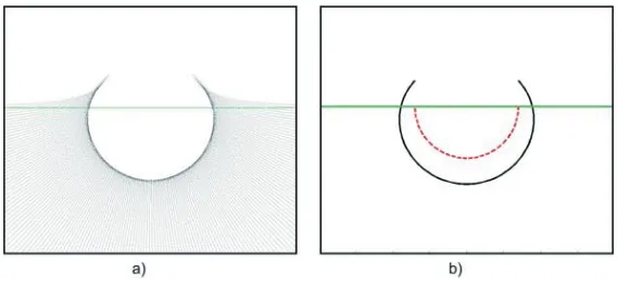
(23)Figure 3a shows simulated position of the light beams on the screen while Figure 3b shows singular caustic curve (solid line) and initial curve (dash line).
Fig. 3. Position of the light beams on the screen (a), single caustics curve (solid line) and initial curve (dash line) (b).
3 The optical setup
The optical setup consists of a white light source, lenses, a semi-mirror and a digital camera used as a screen. The thickness of models is 3 mm, which is sufficient for the purpose of avoiding the buckling effect. The surface of Araldit is optically flat and needs no preparation, but the surface of carbon fibre-reinforced composite is textured and should be treated. Here, chemical vapour deposition of an aluminium layer is performed; the procedure is taken form Semenski [5]. The applied aluminium layer has the thickness of approximately 20 microns; therefore, it has no influence on the material strength.
Cause of non-transparent properties of composite material only recording in a reflecting light is considered (Figure 4). Semi-mirror is used to make possible perpendicular path of the light rays onto model surface. Light beam comes from the light source (LS) and passes through the convergent lens (L1) and semi-mirror (M) before it illuminates the specimen. After reflection semi-mirror directs the
light on a digital camera (RP) which is used as a screen. Lens (L2) is optional and it can be
Fig. 4. Schematic illustration of the optical setup for recording caustics in reflecting light. Light source (LS), lenses (L), semi-mirror (SM),
model (M) and reference plane (RP).
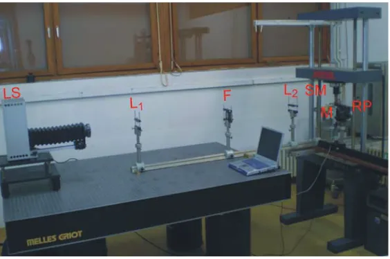
Figure 5 shows elements of the optical setup in the laboratory. All elements can be accurately set in optical axis by screws and can be moved along the axis in order to optimize setup. The optimized values and distances for recording clear image are given in Table 1. Large distances between lenses are used to purify the light of unwanted reflections and filter (F) is added to control light intensity on the screen.
The digital camera is set up on the slider which allows continuously changing of z0 which affect
directly on position of initial curve on the specimen.
Fig. 5. Experimental optical setup. Light source (LS), lenses (L), filter (F), semi-mirror (SM), model (M) and reference plane (RP).
With this optical layout virtual image is obtained on the screen. For getting real image it is necessary to add another convergent lens between mirror and digital camera which will invert light through the focus before the screen. Experimental recordings shown that real image is much smaller then virtual one and has no characteristic value to measure.
Table 1. Parameters of the optical setup
fL1 fL2
(divergent lens)
fL2
(convergent lens)
xL2 a b
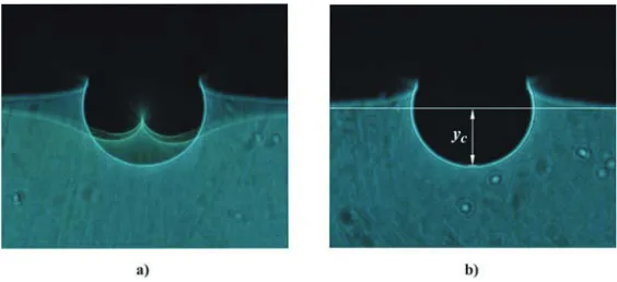
The bigger simple caustics (Figure 6a) is formed on the screen as a reflection from the front surface of the specimen, while the smaller caustics is formed as a reflection from its rear surface. The double effect appears due to photoelastic properties of Araldit B because in the case of rear surface reflection light ray should pass through the specimen. Mathematical description of this effect includes not only surface deformation but also a stress state of a model and can be founded in literature [6]. To avoid reflections from rear surface it is enough to brush it and make it not optically flat (Figure 6b). Characteristic size of caustics is chosen as yc which corresponds to radial
component of singular caustics curve for =0.
Fig. 6. Visual optical effect of caustics recorded on Araldit B in reflected light. Caustics from front and rear surface (a)
and only from front surface (b).
Figure 7 shows the experimentally recorded caustics on the composite material (CFRP131) for the case when the fibers are perpendicular to the loading direction (Figure 4a) and for the case when the fibers are oriented at an angle 45° relative to the direction of the load. The asymmetric optical effect confirms a strong influence of the material orientation on the shape of caustics.
Fig. 7. Visual optical effect of caustics recorded on CFRP131 composites in reflected light. Fibers are oriented perpendicular to the load direction (a)
and at an angle 45° relative to the direction of the load (b).
3 Results and conclusion
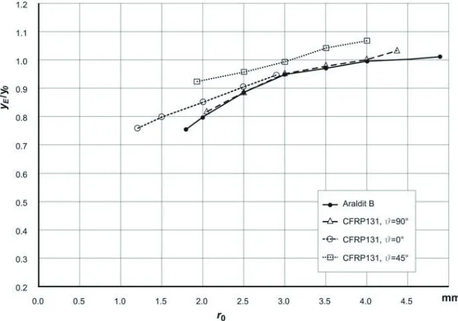
The position of the initial curve on a model depends on few parameters: r0()=r0(F,m,z0,Sij). For
same load condition and same specimen value of r0 can still be changed modifying m (lens L2) or z0
(sliding the camera). Diagram on the Figure 8 shows comparison of analytical and experimental value of characteristic size of caustics. Intensity of contact force was 100 N for Araldit B and 600 N for composite CFRP131. Maximal range of r0 with presented optical setup is between 1mm and 5
Fig. 8. Comparison between experimental and analytical size of caustics for different position of initial curve and different material properties.
The obtained results show that significant differences between analytical and experimental approach for small r0 because analytical model has assumption of elastic material which is not valid
for plasticity region near the contact point. Outside of plasticity region results have good agreement but for value of r0 grater then 5mm size of caustics going down and measuring uncertainty rise up.
The asymmetric optical effect appeared when coordinate axes are not parallel to the principal axes of orthotropy which confirms a strong influence of the material orientation on the shape of caustics.
By varying input parameters, it is revealed that virtual image is sensitive to the intensity of contact force, while the real image is sensitive to the contact force inclination. Also it is noticed that for anisotropic specimen real image is small and has no characteristic value to measure while virtual image is much bigger and clearer for same load condition.
References
1. J. F. Kalthoff, Stress Intensity Factor Determination by Caustics, Proc. of Int. Conf. on Experimental Stress Analysis, Honolulu-Maui-Hawaii, (1982)
2. G. A. Papadopoulos, Fracture Mechanics: The Experimental Method of Caustics and the Det.-Criterion of Fracture, Springer-Verlag publisher, Berlin (1992)
3. S. G. Lehnitskii, Theory of Elasticity of an Anisotropic Body, Mir Publishers, Moscow (1950) 4. A. Baki, Metoda kaustike u analizi kontaktnih problema kompozitnih materijala, PhD thesis,
FSB Zagreb, (2009)