International Journal of Research in Advent Technology, Vol.2, No.9, September 2014
E-ISSN: 2321-9637
Reduction In Total Harmonic Distortion Using
Active Power Filters
Supreet Kaur Saini
1, Mr. Gagandeep Sharma
2, Dr.Sudhir Sharma
3Department of Electrical Engineering, D.A.V.I.E.T., Jalandhar, Punjab, India1, 2, 3 Student, Master of Technology, [email protected]1
Assistant Professor, [email protected]2 Associate Professor and Head, [email protected]3
Abstract-Power Quality issues are becoming the most important concern of today’s power system engineers.
Harmonics play considerable role in deteriorating power quality, called harmonic distortion. Harmonic distortion in electric distribution system is all the time more growing due to the extensive use of nonlinear loads. Active power filters are quite new and rather expensive but they do have various important advantages that should be watched carefully which are inherently current limiting, have no resonance problems, are adaptable, can be configured to either correct the full range of harmonics or to target particular harmonics and being able to balance for harmonics without fundamental frequency reactive power concerns. For the accurate function of the filter, it is essential to determine the magnitude of the currents, which have to be added to load current so as to get rid of high harmonics in the supply current. This manuscript introduces the performance of Active Power Filters which are helpful in removing the total harmonic distortion and also helps in enhancing the power quality of the power system network.
Keywords- Power Quality, Harmonic Distortion, Active Power Filters, Reactive Power
1. INTRODUCTION
A harmonic is a constituent of a cyclic wave having a frequency that is an important multiple of the original frequency. Harmonics are the multiple of the original frequency, and overall harmonic distortion is the involvement of all the harmonic frequency to the original. The by-products of modern electronics are harmonics. Harmonics are the main worries in a power system. Harmonics cause alteration in current and voltage waveforms resulting in worsening of the power system. The first and foremost step for harmonic examination is the harmonics from the non linear loads. The result of such analysis is complex. Over several years, much significance is given to the technique of examination and control of harmonics. Harmonics present in the power system also has non- integer multiples of the fundamental frequency and have a periodic waveform. The harmonics generated by the most common non-linear loads have the following properties: lower order harmonics tend to dominate in amplitude; if the waveform has half-wave symmetry there are no even harmonics. The
various effects of harmonics are Increased transformer or generator heating, Misoperation of protective relays, False breaker tripping, Flickering of lights. Power Quality may be defined as a provision of quality voltages and a system design so that the user of electric power can utilize electric energy from the distribution system successfully, without interference. According to IEEE standards, Power Quality is defined as the concept of powering and grounding electronic apparatus in a way that is appropriate to the operation of that apparatus and compatible with the premise wiring system and other connected equipment.
2. POWER QUALITY PROBLEM:
Any power problem that results in failure or disoperation of customer equipment, manifests itself as an economic burden to the user, or produces negative impacts on the environment.
International Journal of Research in Advent Technology, Vol.2, No.9, September 2014
E-ISSN: 2321-9637
A decline of the normal voltage level between 10 and 90% of the nominal rms voltage at the power frequency, for durations of 0, 5 cycle to 1 minute.
2.2 Voltage Spikes-
Very fast variation of the voltage value for durations from a several microseconds to few milliseconds. These variations may reach thousands of volts, even in low voltage.
2.3 Harmonic Distortions-
Voltage or current waveforms assume non-sinusoidal shape.
2.4 Voltage Fluctuations-
Oscillation of voltage value, amplitude modulated by a signal with frequency of 0 to 30 Hz.
2.5 Noise
Superimposing of high frequency signals on the waveform of the power-system frequency.
To eliminate the ill effects of harmonics active power filters are used. So APF technology is the most resourceful way to compensate for reactive power and terminate lower order harmonics generated by non linear loads. In order to lessen the impact of these power quality troubles, in 1976 Gyugi and Strycula introduced the concept of active filter.
3. ACTIVE POWER FILTERS
Active power filters are simply power electronics converter, specifically designed to inject harmonic currents to the system. The active power filter (APF) is a popular approach for cancelling the harmonics in power system. The main component in the APF is the control unit. The control unit is mainly divided into two parts as follows-
Harmonic Extraction Technique: Harmonic
extraction is the method in which, reference current is produced by using the misleading waveform. Various theories have been established such as p-q theory, d-q theory, frieze controller, PLL with fuzzy logic controller [3], neural network etc. Out of these concepts, more than 60% research works consider using p-q theory and d-q theory due to their accuracy, toughness and informal calculation.
Current Modulator: Current modulator is mainly used
to provide the gate pulse to the active power filter (Inverter). There are many techniques used for giving the gating signals to PWM VSI such as sinusoidal PWM, triangular PWM, hysteresis current controller, adaptive hysteresis current controller, space vector modulation and space vector with hysteresis current controller etc.
The above described two control methods (harmonics extraction method and current modulator method) are the foremost research focus of many researchers in the current years. It may be noted that whichever harmonic extraction technique or current modulator technique can be used independently or together at a time. Apart from these two methods, most of the research works are also given instructions to deal with multi-level inverter control problems.
Active Power Filter Capabilities
International Journal of Research in Advent Technology, Vol.2, No.9, September 2014
E-ISSN: 2321-9637
• Regulating terminal voltage • Compensating the voltage flickering • Non Susceptibility to resonances
Active power filters is the device which generate the same amount of harmonic as generated by the load but 1800 phase shifted. So when these harmonics are inserted into the line at the point of common coupling the load current harmonics are eliminated and utility supply becomes sinusoidal. There are basically two types of active filter: Series active filters and shunt active filters.
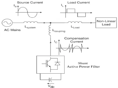
Fig. 1 shows the basic scheme of shunt active power filter which compensate load current harmonics by injecting equal but opposite harmonic compensating current. Basically shunt active power filter works as a current source which injects the harmonic components produced by the load but phase shifted by 180°. As shown in Fig.2 series active power filters operate mainly as a voltage regulator and as a harmonic isolator between the nonlinear load and the utility source.
Fig 1 Basic Scheme of Shunt Active Power Filter
Fig 2 Basic Scheme of Series Active Power Filter
The series active filter injects a voltage component in series with the supply voltage and removes harmonic components in voltage waveforms and therefore can be regarded as a controlled voltage source, compensating voltage sags and swells on the load side. Practically shunt active power filter are more effective and cheaper compared to series active power filters because most of the non linear loads produce current harmonics.
4. SIMULATION RESULTS
Performance of shunt active power filter is checked with the use of MATLAB software. In the proposed scheme two cases have been considered: i) Without Filter ii) With Filter
It is seen that without filter the Total Harmonic Distortion (THD) of the source voltage was 17.92% and with filter the Total Harmonic Distortion (THD) of source voltage decreases to 11.46%.
Fig 3 shows a AC DC converter feeding R-L load without active filter. Fig 4 and Fig 5 represent The Total Harmonic Distortion (THD) of voltage source and current source respectively.
The block diagram in Fig 3 represents the three phase programmable voltage source connected to the transmission line parameters R and L which are known as the Line Constants. The line constants are further connected to the bus bar. The inductive load feeds the rectifier which in turn is shown connected to the R-L load.
Fig 6 shows a AC DC converter feeding R-L load with active filter. Fig 7 and Fig 8 represent The Total Harmonic Distortion (THD) of voltage source and current source respectively.
The block diagram in Fig 6 represents the three phase programmable voltage source connected to the transmission line parameters R and L which are known as the Line Constants. The line constants are further connected to the bus bar. The active filter is connected with the inductive load feeds the rectifier which in turn
International Journal of Research in Advent Technology, Vol.2, No.
Without filter
International Journal of Research in Advent Technology, Vol.2, No.
E-ISSN: 2321-9637
Fig 3: Block Diagram Without Filter
Fig 4: FFT Analysis of Voltage Source
International Journal of Research in Advent Technology, Vol.2, No.
With filter
International Journal of Research in Advent Technology, Vol.2, No.
E-ISSN: 2321-9637
Fig 5: FFT Analysis of Current Source
Fig 6: Block Diagram With Active Filter
International Journal of Research in Advent Technology, Vol.2, No.
Table 1: Comparison of THD with different schemes:
MATLAB
SIMULINK
VOLTAGE
THD%
Without filter 17.92
With filter 11.46
International Journal of Research in Advent Technology, Vol.2, No.
E-ISSN: 2321-9637
Fig 7: FFT Analysis of Voltage Source
Fig 8: FFT Analysis of Current Source
Comparison of THD with different schemes:
CURRENT
THD%
0.53
0.46
5. CONCLUSION
In this paper the performance analysis of active power filter have been carried out. Simulation results show the effectiveness of active power filter for harmonic elimination in distorted source current and source voltage. Considering two cases i.e. withou active filter and with active filter the Total Harmonic Distortion (THD) for source
17.92% to 11.46% and that for source current reduces from 0.53% to 0.46%.
International Journal of Research in Advent Technology, Vol.2, No.9, September 2014
International Journal of Research in Advent Technology, Vol.2, No.9, September 2014
E-ISSN: 2321-9637
REFERENCES
[1] Isak I. Mujawar, Irfan I. Mujawar, Devendra L. Raokhande, D.R.Patil and U. Gudaru, “An Innovative TCR Compensator for Closed Loop Reactive Power Compensation of Dynamic Loads” International Journal Of Innovative
Research In Electrical, Electronics,
Instrumentation And Control Engineering, Vol. 2, Issue 1, January 2014.
[2] Rahul R. Patel, Amit Gorasiya and Biren A. Patel, “Power Quality Improvement Using Shunt Active Power Filter By Hysteresis Current Control” International Journal Of Innovative Research And Studies, Vol 3 Issue 3, March 2014.
[3] Nirvisha V. Vyas, Nitin H. Adroja and Ashish Doorwar, “Modelling of Reactive Power & Unity Power Factor Control of Inductive Load” National Conference On Emerging Trends In Computer And Electrical Engineering, pp 293-297, 2014. [4] Sandeep G J S M and S K Rasoolahemmed,
“Importance of Active Filters for Improvement of Power Quality” International Journal of Engineering Trends and Technology (IJETT) - Volume4Issue4- April 2013.
[5] Anil Kumar and Jatinder Singh, “Harmonic Mitigation And Power Quality Improvement Using Shunt Active Power Filter” International Journal Of Electrical, Electronics and Mechanical Controls, Volume 2 Issue 2 May 2013.
[6] K. Sarasvathi and R. Rajalakshmi, “Performance Analysis Of Shunt Active Filter Using
Different Controllers” International Journal of Engineering Trends and Technology (IJETT) – Volume4Issue5- May 2013.
[7] Xiaochu Qiu, Peng Shi, Jian Xiao and Jun Wang, “A Novel Active Filter For Unbalanced 3-phase 4-Wire Power System Based On Linear Adaptive Notch Filter And Fuzzy Adaptive Hysteresis Controller” International Journal of Innovative Computing, Information and Control- Vol 9 No.6, pg 2619-2634, June 2013.
[8] Kanchan Chaturvedi, Dr. Amita Mahor and Anurag Dhar Dwivedi, “Active Power Filter Techniques for Harmonics Suppression in Non Linear Loads” International Journal of Scientific Engineering and Technology, Volume No.1, Issue No.2 pg:123-127, April 2012.
[9] D. Sangeeta Sarali and P. Shailaja, “Mitigation Of Harmonics Using Thyristor Based 12 Pulse Voltage Source PWM Rectifier” International Journal Of Research In Engineering And Technology, Volume 1 Issue 3, Pg 267-270, November 2012.
[10] C. Nalini Kiran, Subhransu Sekhar Dash and S. Prema Latha, “A Few Aspects of Power Quality Improvement Using Shunt Active Power Filter”