120
Behavior of Plate Element with Change in Boundary
Conditions
Aparna R. Nikumbh, Prof. Abhinandan R. Gupta
Dept of Civil Engg., College Of Engineering & Technology, AkolaAbstract-The finite element method is a numerical technique for solving problems which are described by
partial differential equations or can be formulated as functional minimization. FEM works effectively even for complex structures with effective results or outcomes. It converts a infinite number of degree problem to a finite number of degree problem using discretization. In this paper, the behavior of plate subjected to different loading condition with various boundary conditions such as fixed clamping, simply supported condition and free boundary conditions are studied.
Keywords: Finite element method, boundary conditions, maximum deflection.
1. INTRODUCTION
Finite element method is a popular computer aided numerical method based on the discretisation of the domain, structure or continuum into number of elements and obtaining the solution. The finite element method is a numerical technique for solving problems which are described by partial differential equations or can be formulated as functional minimization. A domain of interest is represented as an assembly of finite elements. Approximating functions in finite elements are determined in terms of nodal values of a physical field which is sought. a continuous physical problem is transformed into discretized finite element problem with unknown nodal values. For a linear problem a system of linear algebraic equations should be solved. Values inside finite elements can be recovered using nodal values. In this paper, the behaviour of plate subjected to different loading condition with various boundary conditions is studied.
2. LITERATURE REVIEW
B. Sidda Reddy, A. Ramanjaneya Reddy, J. Suresh Reddy and Vijaya Kumar Reddy: In this
paper, a nuber of finite element analyses have been carried out for various side-to-thickness ratios and modulus ratios to study the effect of transverse shear deformation on deflection and stresses of laminated composite plates subjected to uniformly distributed load. the numerical results showed on the deflection and stresses, that the effect of coupling is to decrease the deflections with the increase in the aspect ratio and modulus ratio and increase the stresses with the increase in the side-to-thickness ratio and modulus ratio. Hence the accurate understanding of their structural behaviour is required, such as deflection and stress.
S. Timoshenko and Woinowsky Krieger - Theory of plate and shells - 1987 : This book is
written by author is saga of all knowledge and solutions of each and every complications regarding plate and continuum structures. Author provide us the value of coefficients for deflection, moments and shear force for various plates with varying boundary conditions, which is based on classical method.
Devidas Patil, P. G. Damle, Dinesh Shinde:
Generally plates are subjected to different load conditions which ay change by fixing different edges of the plate, that cause deflection transverse to the plate. In this paper a vibration analysis of a five layer composite plate is presented at different boundary condition. A composite plate having five layers is modeled in ANSYS parametric design language platform and finite element procedure is followed.
Ray W. Clough, James L. Tocher :
A study is made of the relative accuracy provided by seven different types of finite elements in the approximate analysis of plate bending. The Kirchoff's plate bending theory is assumed, and stiffness matrices for three rectangular and four triangular elements are considered. Analyses are made with each of these elements of the central deflection, using five different mesh sizes. They are found to give the correct answer which converge towards the correct answer as the mesh size is refined.
J. E. Ashton and J. m. Whitney used the Ritz
121 W = aij i(x) j(y)
i=1 j=1
Then they used two ways to select i(x) and j(y):
Way 1, select the functions s polynomials,
i(x) = (x – ax ) xi-1
j(y) = (y – ay ) y j-1
then they got the results
qa
wmax = 0.00133 , (3-30) D
The error is 5.6%.
Way 2, select the function as,
i(x) = .9825cos(4.73x/a)
- .9825cosh(4.73x/a)+sin(4.73x/a)-sinh(4.73x/a)
j(y) = .9825cos(4.73y/a)
- .9825cosh(4.73y/a)+sin(4.73y/a)-sinh(4.73y/a)
then they got the result
qa
wmax = 0.00134 D
The error is 6.3%.
CONCEPT:
There are four basic types of structures: trusses, cables & arches, framed structures, continuum structures. Continuum structures like membrane plates or shells have much less thickness as compared to its other dimensions. In this paper, the behaviour of plate subjected to different loading condition with various boundary conditions is studied.
There are two methods of analysis.
1. Classical method: It gives us realistic solutions but quite cumbersome and sometimes becomes most impossible for complex structures to analyze for given loading and boundary conditions.
2. Approximate method: Its includes finite difference method, finite element method and finite
Case Consideration and Observations:
CASE I : Rectangular plate simply supported from all sides.
Consider a plate of 4m x 4m ABCD, simply supported on all sides. Plate is subjected to a uniform pressure of intensity 6 KN/m2, and having thickness 0.12m. Take mesh size h=1m.
Discretization of plate with 25 nodal points. Plate ABCD 4mx4m subjected to pressure 6 KN/m2
Since the loading and boundary conditions are symmetric about two axes, only quadrant of the plate is considered for analysis. Also displacement is 0 along the supports.
w1=w2=w3=w4=w5=w10=w15=w20=w25=w24= w23=w22=w21=w16=w11=w6=0
After computational analysis of the same problem we get the following results.
1.00m
4.00m
A B
C
D 12
13 12 12
12 17
17
17 17
Load 1
X Y
122 Table no. 1 : Summary of node displacements.
Horizontal Vertical Horizontal Resultant
Node L/C X mm Y mm Z mm Mm
Max X S. Supported 1 LOAD CASE 1 0 0 0 0
Min X S. Supported 1 LOAD CASE 1 0 0 0 0
Max Y S. Supported 1 LOAD CASE 1 0 0 0 0
Min Y 13 1 LOAD CASE 1 0 -1.95 0 1.95
Max Z S. Supported 1 LOAD CASE 1 0 0 0 0
Min Z S. Supported 1 LOAD CASE 1 0 0 0 0
Max rX 24 1 LOAD CASE 1 0 0 0 0
Min rX 8 1 LOAD CASE 1 0 0 0 0
Max rY S. Supported 1 LOAD CASE 1 0 0 0 0
Min rY S. Supported 1 LOAD CASE 1 0 0 0 0
Max rZ S. Supported 1 LOAD CASE 1 0 0 0 0
Min rz S. Supported 1 LOAD CASE 1 0 0 0 0
Max Rst 13 1 LOAD CASE 1 0 -1.95 0 1.95
CASE II: Rectangular plates with two opposite
edges simply supported and the other two edges
clamped
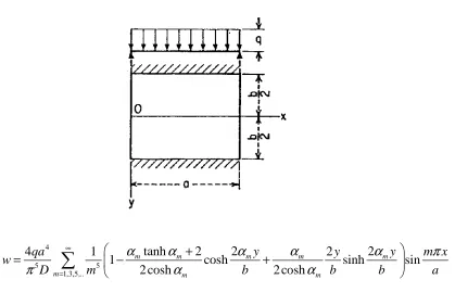
Assume that the edges x=0 and x=a of the rectangular plate, shown in the figure are simply supported and the other two edges are clamped. The deflection of the plate under any lateral load can be obtained by first solving the problem on the
assumption that all the edges are simply supported and then applying bending moments along the edges by the action of lateral load. In this manner many problems can be solved by combining the solutions of the preceding articles. Unifomly Loaded plates. Assuming that the edges of the plate are simply supported, the deflection is -
4
5 5
1,3,5,..
tanh
2
2
2
4
1
2
1
cosh
sinh
sin
2 cosh
2 cosh
m m m m m
m m m
y
y
qa
y
m x
w
D
m
b
b
b
a
α
α
α
α
α
π
π
α
α
∞
=
+
=
−
+
123
5 5
1,3,5,..
1
cosh
sinh
sinh
2 cosh
2 cosh
m m m
w
D
m
a
a
a
π
=α
α
α
=
−
+
∑
...(a) And the slope of the deflection surface along the edge y=b/2 is
(
)
3
4 4
1,3,5,... / 2
2
1
sin
mtanh
m1
mtanh
mM y b
w
qa
m x
y
π
D
m
a
π α
α
α
α
∞
= =
∂
=
−
+
∂
∑
...(b)
To eliminate and thus to satisfy the actual boundary conditions we distribute along the edges y= +- b/2 the bending moment My is given by the series
( )
1
/ 2
sin
y y m
m
m x
M
b
E
a
π
∞
=
= ±
=
∑
...(c)
And we determine the coefficients Em so as to make the slope produced by these moments equal and opposite to that given by expressions (b). the corresponding slope along the edge y= b/2 is
(
)
1,3,5,...
sin
tanh
tanh
1
2
m m m m m mm x
a
a E
D
m
π
α α
α
α
π
∞
=
− −
∑
...(d)
Equating the negative of the quantity to expression (b), we find that
(
)
(
)
2 3 3
tanh
1
tanh
4
tanh
tanh
1
m m m m
m
m m m m
qa
E
m
α
α
α
α
π
α
α α
α
−
+
=
−
−
...(e)
Hence the bending moment along the built in edges are
( )
2(
(
)
)
3 3
/2
1,3,5,...
sin
tanh
1
tanh
4
tanh
tanh
1
m m m m
y y b
m m m m m
m x
qa
a
M
m
π
α
α
α
α
π
α
α α
α
∞ =±
=
−
+
=
−
−
∑
...(f)
The maximum numerical value of this moment occurs at the middle of the sides, where x=a/2. Series (f) converges rapidly, and the maximum moment can be readily calculated in each particular case. for example the first thre terms of sides (f) give -qa3 as the maximum moment in square plate.
In the general case this moment can be represented by the formula where is the numerical factor, the magnitude of which depends on the ratio a/b of the sides of the plate. Several values ofthis coefficient are given in the table.
Substituting the values (e) of the coefficients Em in expression
2
2 2
1
sin
tanh
cosh
sinh
2
mcosh
m m m mm x
a
a
m y
m y
m y
w
E
D
m
a
a
a
π
π
π
π
α
α
π
α
∞
=
=
−
∑
we obtain he deflection surface produced by the moments My distributed
Table 2: Constants
α β β γ
,
1,
2,
for a rectangular plate with two edges simply supported and two edges clamped (Fig) v=0.3 and b>aa/b x=a/2 , y=0 4 max
qb
w
D
α
=
α
0.002602 0.00260
[image:4.595.148.517.563.772.2]124
1.4 0.00240
1.3 0.00234
1.2 0.00223
1.1 0.00209
Table 3. For the condition b>a
b/a wmax
1 0.00192
1.1 0.00251
1.2 0.00319
1.3 0.00388
1.4 0.00460
1.5 0.00531
1.6 0.00603
1.7 0.00668
1.8 0.00732
1.9 0000790
2.0 0.00844
3.0 0.01302
Along the edges
4
1 5 5
1,3,5,...
sin
2
cosh
m m
m x
qa
a
w
D
m
π
π
α
∞
=
= −
∑
(
)
(
)
tanh
1
tanh
sinh
tanh
cosh
tanh
tanh
1
m m m m
m m
m m m m
m y
m x
m y
a
a
a
α
α
α
α
π
π
α
α
π
α
α α
α
−
+
−
−
−
...(g) The deflection at the centre is obtained by substituting x=a/2, y=0 in expression (g). Then
( )
( )
(
(
(
)
)
)
1
4 2
1 max 5 5
1,3,5,...
tanh
1
tanh
1
tanh
2
cosh
tanh
tanh
1
m
m m m m
m m
m m m m m m
qa
w
D
m
α
α
α
α
α
α
π
α
α
α α
α
− ∞
=
−
+
−
=
−
−
∑
This is rapidly converging series, and the deflection from the deflection produced from the high degree of accuracy by taking only a few terms. In the case of square plate, for example, the first term alone gives the deflecion correct to three significant figures, and we obtain
3 1
0.00214
qa
w
D
=
Subtracting this deflection from the deflection produced at the centre by the uniform load, we obtain finally for the deflection of a uniformly loaded square plate with two simply supported and the two clamped edges the value
3
0.00192
qa
w
D
=
In the general case the deflection at the centre can be represented by the formula,
3
qa
w
D
α
=
Several values of numerical factor are given in the table.
CASE III: Rectangular plate with two opposite edges simply supported and other two edges clamped.
[image:5.595.374.535.435.601.2]Consider a plate of 4m x 4m ABCD, side AB and CD are clamped while AD and BC are simply supported. plate is subjected to a uniform pressure of intensity q KN/m2, and having thickness 0.12m. Take mesh size h=1m.
Table no. 4 Summary of node displacements
Horizo ntal
Verti cal
Horizo ntal
Resul tant No
de
L/C X mm Y mm
Z mm Mm
M ax X
13 1 LO AD CA
0
-0.89 6
125 Mi
n X
12 1 LO AD CA SE 1
0
-0.66 6
0 0
M ax Y
18 1 LO AD CA SE 1
0
-0.50 1
0 0
Mi n Y
17 1 LO AD CA SE 1
0
-0.37 5
0 0.816
M ax Z
7 1 LO AD CA SE 1
0
-0.37 5
0 0
Mi n Z
8 1 LO AD CA SE 1
0
-0.50 1
0 0
M ax rX
9 1 LO AD CA SE 1
0
-0.37 5
0 0.472
Mi n rX
14 1 LO AD CA SE 1
0 -0.66 0 0.472
M ax rY
19 1 LO AD CA SE 1
0
-0.37 5
0 0
Mi n rY
1 LO AD CA SE 1
0 0 0 0
M ax rZ
1 LO AD
0 0 0 0
1 Mi
n rz
1 LO AD CA SE 1
0 0 0 0
M ax Rs t
1 LO AD CA SE 1
0
-0.89 6
0 0.896
CASE IV : Rectangular plate with three edged simply supported and one edge built in.
Consider plate of 4m x 4m ABCD. Plate is subjected to a uniform pressure of intensity q KN/m2, and having thickness 0.12m. Taking mesh size h=1m.
According to given boundary condition and loading condition, nodes having unknown deflection are 7, 8,8 12, 13, 17 and 18 only.
[image:6.595.305.529.81.279.2]Rectangular plate with three edged simply supported and one edge built in.
Table no. 11 : summary of nodes displacements.
Horizo ntal
Verti cal
Horizo ntal
Resul tant
7 8
9
14
13
12
11 6
16 17
18 19
20 15 10 5 4
3
2
1
21 22
23 24
25
Load 1
X Y
126 No
de
L/C X mm Y mm
Z mm Mm
M ax X
1 1 LO AD CA SE 1
0 0 0 0
Mi n X
1 1 LO AD CA SE 1
0 0 0 0
M ax Y
12 1 LO AD CA SE 1
0
-0.97 0
0 0.970
Mi n Y
13 1 LO AD CA SE 1
0
-1.29 6
0 1.296
M ax Z
7 1 LO AD CA SE 1
0
-0.80 2
0 0.802
Mi n Z
8 1 LO AD CA SE 1
0
-1.09 6
0 1.096
M ax rX
17 1 LO AD CA SE 1
0
-0.47 8
0 0.478
Mi n rX
18 1 LO AD CA SE 1
0
-0.65 3
0 0.653
M ax rY
1 1 LO AD CA SE 1
0 0 0 0
Mi n rY
1 1 LO AD
0 0 0 0
CA SE 1 M
ax rZ
15 1 LO AD CA SE 1
0 0 0 0
Mi n rZ
11 1 LO AD CA SE 1
0 0 0 0
M ax Rs t
13 1 LO AD CA SE 1
0
-1.29 6
0 1.296
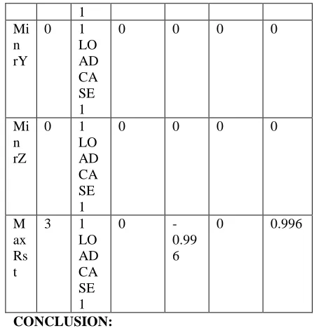
CASE III : Rectangular plate with one or two adjacent edges simply supported and other edges built in.
Consider plate of 4m x4m ABCD. Plate is subjected to a uniform pressure intensity q KN/m2, and having thickness 0.12m. Take mesh size h=1m.
Rectangular plate with one or two adjacent edges
simply supported and other edges built in.
1 2
4
2 3
5
4 5
6
Load 1
X Y
127 Horizo
ntal
Verti cal
Horizo ntal
Resul tant No
de
L/C X mm Y mm
Z mm Mm
M ax X
0 1 LO AD CA SE 1
0 0 0 0
Mi n X
1 1 LO AD CA SE 1
0
-0.67 7
0 0.677
M ax Y
2 1 LO AD CA SE 1
0
-0.81 8
0 0.818
Mi n Y
3 1 LO AD CA SE 1
0
-0.99 6
0 0.996
M ax Z
4 1 LO AD CA SE 1
0
-0.41 3
0 0.413
Mi n Z
0 1 LO AD CA SE 1
0 0 0 0
M ax rX
0 1 LO AD CA SE 1
0 0 0 0
Mi n rX
5 1 LO AD CA SE 1
0
-0.50 1
0 0.501
M ax rY
6 1 LO AD CA SE
0
-0.25 2
0 0.252
Mi n rY
0 1 LO AD CA SE 1
0 0 0 0
Mi n rZ
0 1 LO AD CA SE 1
0 0 0 0
M ax Rs t
3 1 LO AD CA SE 1
0
-0.99 6
0 0.996
CONCLUSION:
For making structure safe and durable , it is utmost important to analyse the structure for various possible practical conditions and design on the base of it. Some important parameters that should be considered are bending moment, shear force , deflection etc. and the factors responsible for making difference are geometry , dimensions , material used and boundary conditions. One such factors influence is suited in this paper and behavior of plat or slab is studied for various boundary condition subjection. Thus, this study helps to analyse and review effect of support or boundary conditions on stability of structure and probable design consideration.
REFERENCES
[1] B. Sidda Reddy, A. Ramanjaneya Reddy, J. Suresh Reddy and Vijaya Kumar Reddy [2] S. Timoshenko and Woinowsky Krieger -
Theory of plate and shells - 1987; MC Graw Hill Books Company USA.
[3] Devidas Patil, P. G. Damle, Dinesh Shinde [4] Ray W. Clough, James L. Tocher, Finite
Element Stiffness matrices for analysis of plate bending.
[5] L.F. Greimann nd P.P. Lynn; finite element analysis of plate bending with transverse shear deformation.
[6] J.E. Ashton, J. M. Whitney, Theory of Laminated Plates, TECHNOMIC Publishing Co., Inc, 1970.
[7] Goerge Lubin, Handbook of composites, VAN NOSTRAND REINHOLD COMPANY, 1982 [8] Rudolph Szilard, Theory and Analysis of plates,
[image:8.595.306.530.81.315.2]