ACS Feed Compact Multiband Antenna for Personal Wireless
Communication Applications
Avinash Tambe*, Rekha Labade, Shankar B. Deosarkar, and Rahul Parbat
Abstract—In this article, the design and analysis of a compact asymmetrical coplanar strip (ACS) feed multiband monopole antenna operating over the frequency range of Bluetooth/IMT-E (2.4–2.484/2.5– 2.6 GHz), worldwide interoperability for microwave access (WiMAX: 3.3–3.6 GHz) and wireless local area network (WLAN: 5.15–5.825 GHz) for Personal Wireless Communication Systems (PWCS) applications has been investigated. The proposed antenna consists of a semi-circular arc and L-shaped stub which forms a vertically flipped G structure that facilitates the multi-band operation at 2.4 GHz and 3.5/5.5 GHz respectively. The antenna is fabricated on a low cost FR-4 substrate having thickness of 1 mm and has compact dimensions of 24×10 mm2. The proposed antenna yields a highly isolated measured impedance bandwidth of 2.3–2.7 GHz, 3.25–3.65 GHz and 5.1–6 GHz for Bluetooth/IMT-E, WiMAX and WLAN bands respectively and exhibits symmetrical radiation pattern, stable gain across all operating frequency bands which makes the antenna a suitable candidate for PWCS applications.
1. INTRODUCTION
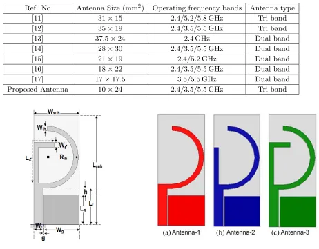
In these days, antenna design has received significant importance. The design of multi-band antenna for 2.4 GHz Bluetooth IEEE 802.11 b/g (2.4–2.484 GHz), 3.5 GHz WiMAX IEEE 802.16 (3.4–3.6 GHz), 5.2/5.8 GHz WLAN IEEE 802.11 a (5.15–5.35 GHz and 5.725–5.825 GHz) and 5.5 GHz HIPERLAN2 (5.47–5.725 GHz) due to its wide range of usability in almost all commercial communication devices such as smart-phones, laptops, tablets, phablets, etc. is especially demanding. Antennas, an integral part of such wireless communication systems, are subjected to very stringent specifications such as light weight, compact structure, low profile, robustness and conform-ability and are expected to grab as much spectrum as possible to provide multi-band or broadband operation [1–4]. The design of several multi-band antenna satisfying some of these specifications have been reported in [5–10]. However, integration of these antennas with RF-MIC circuits with limited access to only service in WiMAX/WLAN frequency bands is a difficult task. Asymmetrical coplanar strip (ACS) feed multiband antennas provide easy integration solutions with RF-MIC have been reported in [11–17]. In general, an ACS feed antenna provides about 50% size reduction compared to the traditional CPW feed antenna as only one half the ground plane of the CPW structure is considered [16]. Table 1 shows comparison of the existing ACS feed multiband antenna with the proposed antenna. The proposed antenna has the most compact dimensions and satisfactory stable gain and provides services in 2.4 GHz Bluetooth, 3.3/5.5 GHz WiMAX, 2.4/5.2/5.8 GHz WLAN frequency bands with acceptable gain of 4.5 dB.
2. ANTENNA DESIGN
The configuration of the proposed tri-band Bluetooth, WiMAX and WLAN antenna is shown in Figure 1. The proposed antenna is designed and analyzed using commercial electromagnetic simulation software
Received 19 August 2015, Accepted 22 September 2015, Scheduled 13 October 2015
* Corresponding author: Avinash Tambe ([email protected]).
Table 1. Comparative analysis of the proposed antenna with existing ACS feed multiband antennas.
Ref. No Antenna Size (mm2) Operating frequency bands Antenna type
[11] 31×15 2.4/5.2/5.8 GHz Tri band
[12] 35×19 2.4/3.5/5.5 GHz Tri band
[13] 37.5×24 2.4 GHz Dual band
[14] 28×30 2.4/3.5/5.5 GHz Dual band
[15] 21×19 2.4/5.2 GHz Dual band
[16] 18×22 2.4/3.5/5.5 GHz Dual band
[17] 17×17.5 3.5/5.5 GHz Dual band
Proposed Antenna 10×24 2.4/3.5/5.5 GHz Tri band
Figure 1. Geometrical configuration of the proposed ACS fed tri-band antenna.
(a) (b) (c)
Figure 2. Different stages of evolution of the proposed antenna.
HFSS. The proposed antenna is printed on a single-sided low cost FR-4 substrate having thickness of 1 mm with dielectric constant of 4.4, loss tangent of 0.02 and has substrate dimensions of 0.19λ×0.08λ with respect to first resonance frequency of 2.4 GHz. The proposed antenna consists of a 50 Ω monopole feed line of widthWf(= 2 mm), asymmetrical coplanar ground plane at a distance ofg(= 0.5 mm) from
feed line, a semi-circular arc and inverted L-shaped radiating elements. The triple-band performance of the proposed antenna is obtained by controlling the electrical lengths and widths of these radiating elements. By choosing the dimensions of the radiating semi-circular arc and L-shaped element equal to quarter-wavelength at the desired operating resonance frequencies, the proposed antenna can be designed to operate over Bluetooth, WiMAX and WLAN frequency bands, respectively.
The optimized parameters of the proposed antenna are: Lsub = 24 mm, Wsub = 10 mm, Wg =
7.75 mm,Lg = 6.5 mm,Lf = 8 mm,Wf = 2 mm,g= 0.25 mm,h= 1.5 mm,Wib= 1 mm,Rib= 6.8 mm,
Ll= 12.5 mm, Wl= 1 mm.
Figure 1 shows the geometrical configuration of the proposed ACS feed triple-band antenna. Figure 2 and Figure 3 show different stages of evolution of the proposed antenna and corresponding simulated S11 replicating the triple band operation of the proposed antenna, respectively.
Figure 3. Simulated S11 at different stages of evolution of the proposed antenna.
Figure 4. Geometrical configuration of L-shaped stub.
The radius of this semi-circular radiating arc, Rib, is calculated using Equation (1), given by:
Cib = πRib (1)
Cib = C0
4fibreff
(2)
reff =
r+ 1
2 (3)
whereC0 stands for the velocity of light in free space andreff the effective relative permittivity of the
substrate.
In Antenna-2, the feed line is further extended to achieve the second resonance at 5.5 GHz. The extended length of the feed line provides a quarter guided wavelength, i.e., (λg/4) electrical path for
the 5.5 GHz resonance frequency as shown in Figure 3. However, to achieve the third resonance in the proposed antenna (i.e., Antenna-3), a vertical stub is added to this extended feed line (as shown in Figure 2(c)), which provides a quarter guided wavelength, i.e., (λg/4) electrical path for the 3.5 GHz
resonance frequency; thus providing two resonance frequencies centered at 3.45 GHz and 5.5 GHz and, the triple band operation at 2.4 GHz, 3.5 GHz and 5.5 GHz for Bluetooth, WiMAX and WLAN frequency bands respectively as shown in Figure 3. The total length,Llof the inverted L-shaped stub, is calculated for centre frequency,fr= 5.5 GHz, governed by Equation (4), and given as:
Ll= 4f Co r√reff
(4)
Thus, the calculated electrical lengths of the L-shaped stub are: Ll/4 = 8.3 mm for the resonance
frequency of fr = 5.5 GHz and Ll/4 = 12.98 mm for the resonance frequency of 3.5 GHz, while the
optimized dimensions are Ll/4 = 8 mm and Ll/4 = 12.5 mm respectively (as shown in Figure 4).
In order to get more physical insights of the triple band operation in the proposed ACS feed antenna, the current distribution at sampling resonance frequencies of 2.4 GHz, 3.5 GHz and 5.5 GHz is observed. As shown in Figure 5, at resonance frequency of 2.4 GHz, a maximum current concentration along the semi-circular radiating arc is observed which indicates the first resonance frequency at 2.4 GHz, while at resonance frequency of 3.5 GHz, current concentration in forward direction along the entire L-shaped stub structure is observed. This indicates the second resonant frequency at 3.5 GHz corresponding to the (λg/4) length of L-shaped stub. However, at fr = 5.5 GHz, a reverted current flow concentrated
along the extended feed line is observed. This indicates that the extended feed line structure provides a third resonance frequency at 5.5 GHz. Furthermore, to support the above aforementioned statements and get more physical insights in the operating principle of the proposed antenna, parametric analysis and radiation pattern characteristics are investigated.
As depicted in Figure 6, by increasing the radiusRib of the semi-circular radiating arc, decrease in
the resonance frequency of the 2.4 GHz band is observed. This is because as the radius —Ribincreases,
the circumference Cib, governed by Equation (1), increases, as a consequence the resonance frequency
(a) (b) (c)
Figure 5. Current distribution at sampling frequencies of (a) 2.4 GHz, (b) 3.5 GHz and (c) 5.5 GHz respectively.
Figure 6. Simulated S11 characteristics of the proposed antenna with varied Rib.
Figure 7. Simulated S11 characteristics of the proposed antenna with varied Ll.
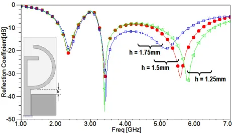
Figure 8. Simulated S11 characteristics of the
controlled. Similarly, by changing the electrical length of the L-shaped stub the resonance frequency at 3.5 GHz and 5.5 GHz can be controlled simultaneously, as observed in Figure 7.
Other parameters that affect the performance of the proposed antenna are: height-h between radiating elements and gap-g between feed line and asymmetrical coplanar ground plane. The height (h) mainly affects the third resonance frequency of WLAN frequency band. At resonance frequency of 5.5 GHz, the current on the antenna flows in a reverse direction on both radiating element and asymmetrical coplanar ground plane. Reducing height (h) changes the total surface radiating area of the asymmetrical coplanar ground plane and hence affects the WLAN resonance frequency as observed in Figure 8. Variation in gap-g between feed line and asymmetrical coplanar ground plane does not significantly affect the operational resonance frequencies of the proposed antenna; however, small change in the bandwidth of each of the operational bands is observed as shown in Figure 9.
3. RESULTS AND DISCUSSIONS
The proposed ACS feed triple band antenna is fabricated (shown in the inset of Figure 10), and its reflection coefficient characteristics is measured in-house using Agilent Fieldfox Vector Network Analyzer (VNA: N9916A) in an open area test site. The simulated and measured impedance bandwidths along with the fabricated prototype of the proposed antenna are shown in Figure 10.
Figure 10. Simulated and measuredS11along with fabricated prototype (given in inset) of the proposed ACS feed triple band antenna.
The measured −10 dB impedance bandwidths are: 350 MHz (2.35–2.7 GHz) with first resonance at 2.35 GHz, 400 MHz (3.25–3.65 GHz) with second resonance at 3.4 GHz and 900 MHz (5.1–6 GHz) with third resonance centered at 5.3 GHz and 5.7 GHz, considering the cable effects. This makes the proposed antenna suitable for operation of Bluetooth (2.4–2.484 GHz)/WiMAX (2.3–2.4 GHz)/IMT-E (2.5–2.69 GHz)/WLAN (2.4–2.484 GHz), WiMAX (3.3–3.6 GHz) and WLAN (5.15–5.825 GHz)/DSRC (5.9–6 GHz). Small discrepancy between simulated and measured results can be observed due to deficiency in fabrication process of the prototype, uncertainty of thickness and/or the dielectric constant r of the FR-4 substrate, quality of SMA connectors and losses incurred by cables connecting the
prototype and VNA. However, at low frequencies, the electrical size of the ground plane becomes relatively smaller than operating wavelength, thus a part of the connecting cables attached to the VNA acts as an additional ground plane for the antenna that provides electrical path for some current flowing back from antenna to the feeding cable [16].
(a)
(b)
(c)
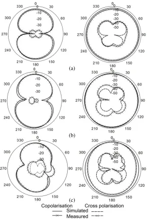
Figure 11. Simulated and measured radiation pattern at sampling frequencies of (a) 2.4 GHz, (b) 3.5 GHz and (c) 5.5 GHz respectively.
The far-field radiation characteristics of the proposed antenna are further investigated as shown in Figure 11. The radiation characteristics are measured in anechoic chamber using a standard double ridged horn antenna (used as reference antenna; Model No: 3115) and antenna measurement system (Turning table, 40 GHz Anritsu RF Source Generator, 40 GHz Anritsu Spectrum Analyzer, connecting cable, L-connectors and radiation pattern plotting software installed on a PC*). Figure 11 shows the simulated and measured radiation patterns at the sampling frequencies of 2.4, 3.5 and 5.5 GHz. Nearly omnidirectional radiation pattern along H-plane and nearly directional radiation pattern (dumbbell-shaped) along the E-plane can be observed at the sampling frequencies. The simulated and measured radiation characteristics are in good agreement while small discrepancy at higher frequencies can be observed due to alignment and measurement errors. The radiation characteristics further deteriorate at higher frequencies due to change in total surface radiating area and generation of complex current modes at these frequencies.
(a)
(b)
(c)
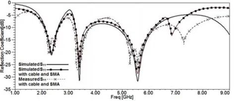
Figure 12. Surface current distribution at sampling frequencies of (a) 2.4 GHz, (b) 3.5 GHz and (c) 5.5 GHz with cable and SMA model.
Figure 13. Simulated and measured S11 with cable and SMA effect.
Figure 14. Measured gain of the proposed antenna.
band is shown in Figure 14. The measured gain varies over the range of 0.5 dB∼4.5 dB and increases with the increase in frequency as the effective area increases at shorter wavelengths. The average simulated radiation efficiency is above 72% across the entire operating frequency band.
4. CONCLUSIONS
A compact and highly isolated ACS feed triple-band antenna has been proposed and investigated. The radiating element consists of a semi-circular arc and L-shaped stub coupled to the feed line above the asymmetrical ground plane. The proposed antenna provides triple-band operation targeting Bluetooth (2.4–2.484 GHz)/WiMAX (2.3–2.4 GHz)/IMT-E (2.5–2.69 GHz)/WLAN (2.4–2.484 GHz), WiMAX (3.3–3.6 GHz) and WLAN (5.15–5.35 GHz and 5.725–5.825 GHz) and 5.5 GHz HIPERLAN2 (5.47–5.725 GHz) and DRSC (5.9–6 GHz) applications. Parametric variation of different parameters allows tuning of different resonance frequencies. The proposed antenna exhibits nearly symmetrical radiation characteristics, stable gain and compact dimensions which makes the proposed antenna a suitable candidate for small and hand-held personal wireless communication system. The coplanar feeding structure allows easy integration solution of the proposed antenna with RF and MIC systems.
ACKNOWLEDGMENT
REFERENCES
1. Labade, R., S. Deosarkar, and N. Pishoroty, “A novel integrated Bluetooth dual band UWB antenna for wireless communication,”International Journal of Microwave and Optical Technology, Vol. 10, No. 3, 195–201, 2015.
2. Fabrs, M. C., “Systematic design of antennas using the theory of characteristic modes,” PhD Dissertation, Feb. 2007.
3. Valderas, D., J. I. Sancho, D. Puente, et al., Ultrawideband Antennas, Design and Application, Imperial College Press, 2010.
4. Labade, R., S. B. Deosarkar, and N. Pishoroty, “Design and implementation of an integrated Bluetooth ultrawideband monopole antenna,” Australian Journal of Basic and Applied Sciences, Vol. 15, No. 8, 60–66, 2014.
5. Sayidmarie, K. H. and T. A. Nagem, “Compact dual-band dual-ring printed monopole antennas for WLAN applications,” Progress In Electromagnetics Research B, Vol. 43, 313–331, 2012. 6. Pei, J., A. G. Wang, S. Gao, and W. Leng, “Miniaturized triple band antenna with defected ground
plane for WLAN/WiMAX applications,”IEEE Antennas and Wireless Propagation Letters, Vol. 10, 298–301, 2011.
7. Lin, C. C., E. Z. Yu, and C. Y. Huang, “Dual-band rhombus slot antenna fed by CPW for WLAN applications,” IEEE Antennas and Wireless Propagation Letters, Vol. 11, 362–364, 2012.
8. Xie, J. J., X. S. Ren, Y. Z. Yin, and S. L. Zuo, “Rhombic slot antenna design with a pair of straight strips and two-shaped slots for WLAN/WiMAX applications,”Microwave and Optical Technology Letters, Vol. 54, No. 6, 1466–1469, 2012.
9. Papantonis, S. and E. Episkopou, “Compact dual band printed 2.5-shaped monopole antenna for WLAN applications,” Progress In Electromagnetics Research C, Vol. 24, 57–68, 2011.
10. Tsai, L.-C., “A triple-band bow-tie-shaped CPW-fed slot antenna for WLAN applications,” Progress In Electromagnetics Research C, Vol. 47, 167–171, 2014.
11. Song, Y., Y. C. Jiao, X. M. Wang, Z. B. Weng, and F. S. Zhang, “Compact coplanar slot antenna fed by asymmetric coplanar strip for 2.4/5 GHz WLAN operations,”Microwave and Optical Technology Letters, Vol. 50, No. 12, 3080–3083, 2008.
12. Li, B., Z.-H. Yan, and T.-L. Zhang, “Triple band slot antenna with U-shaped open stub fed by fed by asymmetric coplanar strip for WLAN/WiMAX applications,”Progress In Electromagnetics Research Letters, Vol. 37, 123–131, 2013.
13. Ashkarli, P., S. Sreenath, R. Sujith, R. Dinesh, D. D. Krishna, and C. K. Aanandan, “A compact asymmetric coplanar strip fed dual band antenna for DCS/WLAN applications,” Microwave Technology Letters, Vol. 54, No. 4, 1087–1089, 2012.
14. Deepu, V., R. K. Raj, M. Joseph, M. N. Suma, and P. Mohana, “Compact asymmetric coplanar strip fed monopole antenna for multiband applications,” IEEE Transactions on Antennas and Propagation, Vol. 55, No. 8, 2351–2357, 2007.
15. Deepu, V., R. Sujith, S. Mridula, C. K. Aanandan, K. Vasudevan, and P. Mohana, “ACS fed printed F-shaped uniplanar antenna for dual band WLAN applications,” Microwave and Optical Technology Letters, Vol. 51, No. 8, 1852–1856, 2009.
16. Naidu, P. V. and R. Kumar, “Design of a compact ACS-fed dual band antenna for Bluetooth/WLAN and WiMAX applications,” Progress In Electromagnetics Research C, Vol. 55, 63–72, 2014.