Available online: https://edupediapublications.org/journals/index.php/IJR/ P a g e | 3069
Analysis of Distributed Power-Flow Controller for improvement of
Transmission line system Reliability
Repalli Guru Pavankumar & B.Moulali
1M.Tech Student, Dept. of EEE, INTELL Engineering College, Affiliated to JNTUA , Andhra Pradesh, India
2Assistant Professor in Dept. of EEE, , INTELL Engineering College, Affiliated to JNTUA, Andhra Pradesh, India
ABSTRACT: This paper presents a new factor within the flexible ac-transmission system (FACTS) own family, called distributed power flow controller(DPFC). The DPFC is derived from the unified power-flow controller (UPFC). The DPFC may be considered as a UPFC with an eliminated common dc hyperlink. The active power alternate between the shunt and series converters, which is through the common dc hyperlink within the UPFC, is now via the transmission strains on the 3rd harmonic frequency. The DPFC employs the disbursed FACTS (D-FACTS) plan, that is to use over one small-size single-phase devices rather than the sole massive-size three-segment series converter within the UPFC. the big vary of assortment converters provides redundancy, thereby increasing the machine responsibility. because the D-FACTS converters ar single part and floating with acknowledge to the bottom, there is not any high-voltage isolation needed between the degree. consequently, the charge of the DPFC system is not up to the UPFC. The DPFC has the equal management capability because the UPFC, which contains the adjustment of the road impedance, the transmission perspective, and also the bus voltage..
I. INTRODUCTION
The electrical power system serves to deliver electrical energy to consumers. An electrical power system deals with electrical generation, transmission, distribution and consumption. In a traditional power system, the electrical energy is generated by centralized power plants and flows to customers via the transmission and distribution network. The rate of the transported electrical energy within the lines of the power system is
referred to as „Power Flow‟ to be more specific, it is the active and reactive power that flows in the transmission lines. During the last twenty years, the operation of power systems has changed due to growing consumption, the development of new technology, the behavior of the electricity market and the development of renewable energies. In addition to existing changes, in the future, new devices, such as electrical vehicles, distributed generation and smart grid concepts, will be employed in the power system, making the system extremely complex.
Available online: https://edupediapublications.org/journals/index.php/IJR/ P a g e | 3070
converter can also provide reactive compensation for the bus. The components of the UPFC handle the voltages and currents with high rating; therefore, the total cost of the system is high. Due to the common dc-link interconnection, a failure that happens at one converter will influence the whole system. To achieve the required reliability for power systems, bypass circuits and redundant backups (backup transformer, etc.) are needed, which on other hand, increase the cost. Accordingly, the UPFC has not been commercially used, even though, it has the most advanced control capabilities. This paper introduces a new concept, called distributed power-flow controller (DPFC) that is derived from the UPFC. The same as the UPFC, the DPFC is able to control all system parameters. The DPFC eliminates the common dc link between the shunt and series converters. The active power exchange between the shunt and the series converter is through the transmission line at the third-harmonic frequency. The series converter of the DPFC employs the distributed FACT
Fig. 1. Flowchart from UPFC to DPFC
Fig. 3. DPFC configuration
(D-FACTS) concept [6]. Comparing with the UPFC, the DPFC have two major advantages: 1) low cost because of the low-voltage isolation and the low component rating of the series converter and 2) high reliability because of the redundancy of the series converters. This paper begins with presenting the principle of the DPFC,
followed by its steady-state analysis. After a short introduction of the DPFC control, the paper ends with the simulation results of the DPFC.
II. DPFC Operating Principle
Within the DPFC, the line offers a standard association between the AC ports of the shunt and therefore the series converters. Therefore, it's doable to exchange energetic electricity via the AC ports. The technique is predicated completely on energy concept of non-sinusoidal elements. in line with the Fourier analysis, non-sinusoidal voltage and last are often expressed because the total of sinusoidal options in distinctive frequencies with exclusive amplitudes. The energetic power as a result of this non-sinusoidal voltage and cutting-edge is defined because the suggest value of the manufactured from voltage and current. Since the integrals of all the move product of phrases with distinct frequencies are zero, the lively strength may be expressed with the aid of:
in which Vi and Ii are the voltage and current at the ith harmonic frequency respectively, and ∅i is the corresponding attitude among the voltage and current. Above Equation suggests that the energetic powers at exceptional frequencies are independent from each different and the voltage or contemporary at one frequency has no influence at the energetic energy at other frequencies.
Available online: https://edupediapublications.org/journals/index.php/IJR/ P a g e | 3071
Neglecting losses, the energetic energy generated at the essential frequency is identical to the strength absorbed at the harmonic frequency. The excessive-bypass filter in the DPFC blocks the essential frequency additives and permits the harmonic components to bypass, thereby offering a go back course for the harmonic additives. The shunt and collection converters, the excessive pass filter out and the ground form a closed loop for the harmonic current.
DPFC Control
To control multiple converters, a DPFC includes three kinds of controllers: principal control, shunt control and collection control, as proven in Figure 3.
The shunt and series control are localized controllers and are accountable for maintaining their very own converters‟ parameters. The crucial control looks after the DPFC features at the power system degree. The function of each controller is indexed:
Central control: The relevant control generates the
reference alerts for both the shunt and series converters of the DPFC. Its control function relies upon at the specifics of the DPFC software at the electricity machine degree, inclusive of energy go with the flow control, low frequency electricity oscillation damping and balancing of asymmetrical components. According to the machine requirements, the significant control offers corresponding voltage reference alerts for the series converters and reactive current signal for the shunt converter. All the reference signals generated by means of the significant control situation the fundamental frequency additives.
Series control: Series control: Each collection converter
has its personal series control. The controller is used to hold the capacitor DC voltage of its very own converter, by the use of 3rdharmonic frequency components, similarly to generating collection voltage at the fundamental frequency as required with the aid of the important control.
Shunt control: The objective of the shunt control is to inject a consistent 3rdharmonic cutting-edge into the road to deliver energetic electricity for the series converters. At the same time, it maintains the capacitor DC voltage of the shunt converter at a consistent fee
through absorbing active energy from the grid at the fundamental frequency and injecting the specified reactive current at the fundamental frequency into the grid.
Figure.3: DPFC control block diagram
DPFC Modeling
To design a DPFC control scheme, the DPFC must first be modeled. This section presents such modeling of the DPFC. As the DPFC serves the power system, the model should describe the behavior of the DPFC at the system level, which is at the fundamental and the 3rd harmonic frequency. The modeling of the switching behavior of converters is not required.
The functions of the series control can be summarized as:
Maintain the capacitor DC voltage of its personal converter by means of the use of the 3rd harmonic frequency additives.
Generate the collection voltage on the fundamental frequency this is prescribed with the aid of the relevant control.
The features of the shunt control are:
Inject a regular third harmonic current into the line to deliver active strength for series converters.
Maintain the capacitor DC voltage of the shunt converter via absorbing lively power from the grid on the fundamental frequency.
Available online: https://edupediapublications.org/journals/index.php/IJR/ P a g e | 3072
grid as prescribed by way of the vital control.
To design a DPFC control scheme, the DPFC need to first be modeled. This phase currents such modeling of the DPFC. As the DPFC serves the power machine, the version must describe the conduct of the DPFC on the system degree, that's on the fundamental and the third harmonic frequency. The modeling of the switching behavior of converters isn't always required.
V. SIMULATION RESULTS
a)Reference voltage for the series converters :
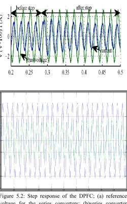
b) Step response of the DPFC: series converter voltage:
Available online: https://edupediapublications.org/journals/index.php/IJR/ P a g e | 3073
d) Step response of the DPFC: active and reactive power injected by the series converter at the fundamental frequency
e) Step response of the DPFC: bus voltage and current at the Δ side of the transformer:
Figure 5.2: Step response of the DPFC; (a) reference voltage for the series converters; (b)series converter voltage; (c) line current; (d) active and reactive power injected by the series converter at the fundamental frequency; (e) bus voltage and current at the delta side of the transformer.
VII. CONCLUSION
Available online: https://edupediapublications.org/journals/index.php/IJR/ P a g e | 3074
transmission perspective, and the bus-voltage value. The common dc hyperlink among the shunt and series converters, which is used for replacing active power inside the UPFC, is eliminated. This electricity is now transmitted thru the transmission line on the third-harmonic frequency. The series converter of the DPFC employs the D-FACTS concept, which uses multiple small single-segment converters as opposed to one huge-size converter. The reliability of the DPFC is greatly elevated due to the redundancy of the collection converters. The overall fee of the DPFC is also tons decrease than the UPFC, due to the fact no high-voltage isolation is required on the collection-converter element and the rating of the additives of is low. it's well-tried that the shunt and series converters within the DPFC will exchange active power on the 3rd harmonic frequency, and also the assortment converters area unit capable of inject controllable active and reactive power on the fundamental frequency.
VIII. REFERENCES
[1] Zhihui Yuan, Jan Braham Ferreira presents a paper on “A FACTS Device: Distributed Power-Flow Controller (DPFC)” on IEEE TRANSACTIONS ON POWER ELECTRONICS, VOL. 25, NO. 10, OCTOBER in 2010
[2] A. E. Emanuel and J. A. McNeill, “Electric power quality,” Annu. Rev. Energy Environ, 1997.
[3] K. L. Thakre presents a paper on “characteristics of factor effecting in voltage sag due to fault in power system,” in Serbian Journal of Electrical engineering. vol. 5, no.1, 2008.
[4] J. R. Enslin, “Unified approach to power quality mitigation,” in Proc. IEEE Int. Symp. Industrial Electronics (ISIE ‟98), vol. 1, 1998.
[5] B. Singh, K. Al-Haddad, and A. Chandra, “A review of active filters for power quality improvement,” IEEE Trans. Ind. Electron.vol. 46, no. 5, pp. 960–971, 1999. [6] A. L. Olimpo and E. Acha, “analysis and modelling of custom power systems by PSCAD/EMTDC,” IEEE Trans. Power Delivery, vol. 17, no.1, pp. 266–272, 2002. [7] P. Pohjanheimo and E. Lakervi, “Steady state analysis of custom power components in power distribution networks,” in Proc. IEEE Power
Engineering Society Winter Meeting, vol. 4, Jan, pp. 2949–2954, 2000.
[8] S. W. H de Haan, and B. Frreira “DPFC control during shunt converter failure,” IEEE Transaction on Power Electronics 2009.