International Journal of Emerging Technology and Advanced Engineering
Website: www.ijetae.com (ISSN 2250-2459,ISO 9001:2008 Certified Journal, Volume 5, Issue 10, October 2015)
66
Breakdown Test on Solid Insulators Using Rod Gap
Umadevi sreedhar
1, Somashekar. B
2, N. Lakshmipthy
31, 2, 3Asst. Professor, Dr. T. Thimmaiah Institute of Technology, KGF, India
Abstract-- Increasing demand in electrical power utilization the need for high quality insulation is in equal demand for efficient generation, transmission and utilization. Based on the improvement in quality of insulation the choice is posed on solid insulators which hare high breakdown strength good thermal conductivity. With the help of rod gap measurement experimental setup, the breakdown voltage and the electrical stress of different solid insulating materials are tested and tabulated. The corresponding graphs are also plotted which gives a finite study of the materials that helps in manufacturing of insulation for various application of the electrical appliances.
Keywords-- High voltage, rod gap, insulating materials
I. INTRODUCTION
Recent increasing in industrial and economic
development the present world, demands the use of more and more electrical energy which has to be transferred efficiently over long distances in large quantities. This is made possible by introducing the higher transmission voltage level in the power system. Rapid growth in power sector of nation has given the opportunity to power engineers to protect the power equipment for reliable operation. It has been seen from the studies conducted by power engineers that one of the main problem in high voltage power equipment is the degradation of insulation i.e., quality of insulation of the equipment used in power system. The high voltage power equipments are mainly subjected with spark over voltage causes by the, switching action or lightening strokes, a protective device is used to determine the safe clearance required for proper insulation level. As we know that without insulation system it is impossible to overcome the losses of electric power so there are mainly four types of insulation such as solid, liquid, gaseous and composites but over these insulators the solid type insulators are more and effectively used because in liquids, more of the liquids are electrical conductor and in gaseous the main problem is ionization so our goal is to study availability of solid insulators and in future expansion to provide more of solid insulators can be utilized. Solid insulators are easily available, having high breakdown strength, tensile strength and good thermal conductivity. The rod gaps are commonly used for measurements of peak values of high voltages and have been adopted by IEC and IEEE as a calibration device.
Many materials are used to make rod like bronze, copper, aluminum, steel, brass and light alloys,The electric breakdown strength of insulated gap between two metal electrodes can be improved considerably when one or both of the electrodes are covered with a coating of dielectric. The effect of the coating depends on the electrode shape, voltage polarity, pre-charging and the duration and form of the applied voltage. In the past several decades, extensive amount of research work has been done to understand the fundamental characteristics of the electrical breakdown. Therefore, electrical breakdown characteristic of small gap under the different applied voltage has its great significance for the design of overhead line, Substation equipment and various insulated HV equipment. There is no piece of electrical equipment that does not depend upon on the electrical insulation in one form or another to maintain the flow of electrical current in the desired path or circuits. The method of rod gap measurement for measuring AC/DC voltages with solid insulators which has been recorded for various solid insulators and hence it been presented. Solid insulator plays very important role, since its breakdown voltages is greater when compare to air, liquid and gaseous insulators. The experiment is conducted at the normal temperature and pressure. In addition to this influence of the humidity on breakdown test has been also considered in this study.
II. EXEPERIMENTAL SETUP FOR MEASUREMENT OF BREAKDOWN VOLTAGE
International Journal of Emerging Technology and Advanced Engineering
Website: www.ijetae.com (ISSN 2250-2459,ISO 9001:2008 Certified Journal, Volume 5, Issue 10, October 2015)
67
The HV electrode is energized from the 50 Hz transformer with a power rating of 15 kVA with a transformation ratio of 230 V/100kV.The test voltages are applied through the filter unit to isolate the noise of the transformer from the measuring circuit and current limiting device for protection in case of complete breakdown and prevent the high frequency current to the high voltage lead. The breakdown voltage is recorded at the inception of the breakdown, where the circuit is immediately disconnected from the supply. A coupling device with connecting cable is associated with the measuring circuit for the measurement of the applied high voltages magnitude.Fig: 1.1 Schematic Circuit showing the source and Breakdown voltage measuring unit using standard rod gap method.
FIG: 1.2 Schematic Circuit showing the source and Breakdown voltage measuring unit using standard ROD gap method
III. BREAKDOWN OF SOLID INSULATING MATERIALS
In solid dielectrics, highly purified and are of perfections, the breakdown strength is high, of the order of 10 MV/cm. The highest breakdown strength obtained under carefully controlled conditions is known as the "intrinsic strength" of the insulator. Dielectrics usually fail at stresses well below the intrinsic strength due usually to one of the following causes.
a. Electromechanical B.D
b. Discharges at the interior of the solid
c. Treeing and Tracking and erosion
d. Breakdown due to high temperatures (Thermal)
e. Breakdown due to electro chemical
f. Deterioration due to chemical reaction
Electromechanical B.D
If electric field is applied between the two electrodes, due to the force of attraction between the charges at the electrode surface, a mechanical force will be exerted on the dielectric This compression decreases the dielectric thickness thus increasing the effective stress.
Breakdown due to discharges at the interior of the solid
Solid insulating materials sometimes contain voids or cavities in the medium or boundaries between the dielectric and electrodes. These voids have a dielectric constant of unity and a lower dielectric strength. Hence the electric field strength in the voids is higher than that across the dielectric. Thus under normal working voltages, breakdown may occur due to the field in the voids exceed their breakdown value. In each of the discharges, there will be heat dissipated in the voids which will cause carbonization of the surface of the voids and erosion of the material. This gradual erosion of the material and consequent reduction in the thickness of the insulating material eventually leads to breakdown.
Deterioration due to discharges at the interior of the solid
Internal discharges leads to gradual deterioration in organic liquid-solid insulators because of
(a) Disintegration of the solid dielectric under the bombardment of electrons set free by the discharges.
(b) Chemical action on the dielectric of the products of ionization of the gas
(c) High all voids in the dielectric can be removed by careful impregnation and these results in an increase in the temperatures in the region of the discharges. Discharge inception stress Ei. The final value Ei then depends on electrical processes which lead to gas formation.
In oil impregnated paper these are
International Journal of Emerging Technology and Advanced Engineering
Website: www.ijetae.com (ISSN 2250-2459,ISO 9001:2008 Certified Journal, Volume 5, Issue 10, October 2015)
68
The stress at which gas is evolved from paper containing appreciable quantities of moisture can be less than 10 V/_m, but increases continuously with increasing dryness and can be higher than 100 V/_m when the paper is thoroughly dry. Except in very dry conditions, the gas first formed arises from electrochemical decomposition of water held in the paper.Then a gas bubble is formed in an oil-paper dielectric at the discharge inception stress Ei, discharges in the bubble decompose the molecules of the oil, resulting in further gas formation and a rapid growth of the bubble. As long as the bubble remains in the dielectric, the inception stress Ei is low, often lower than the rated stress, but resting the dielectric long enough for the gas to dissolve in the oil restores the initial high discharge inception stress. Although on resting Ei improves, permanent damage has been caused by the discharges and this manifests itself in an increase of loss angle and is due to the formation of ions by the discharges. Also, due to the discharges, widespread carbonization occurs.
Surface B.D
Surface flashover
In Surface flashover breakdown of the medium in which the solid is submerged and the role of the solid dielectric is only to pull the field so that the electric strength of the gas is exceeded.
If a piece of solid insulation is inserted in a gas so that the solid surface is perpendicular to the Equiv. potentials at all points, then the voltage gradient is not affected by the solid insulation. For example let us consider a cylindrical insulator placed in the direction of a field which is uniform. Field becomes more intense if solid insulation departs even in detail from the cylindrical shape. If the edges are chipped, an air gap being next to the electrode, and the stress will reach up to 0r times the mean stress in the gap. If the ends of the cylinder are not quite perpendicular to the axis, then [0r is the dielectric constant of the cylinder]. Therefore discharge may occur at a voltage approaching 1/0r times the breakdown voltage in the absence of the cylinder, and these discharges can cause a breakdown.
The three components of the surface flashover are (a) The presence of a conducting film across the surface of the insulation
(b) A mechanism whereby the leakage current through the conducting film is interrupted with the production of sparks,
(c) Degradation of the insulation must be caused by the sparks.
The conducting film is usually moisture from the atmosphere absorbed by some form of contamination. Moisture which is not essential as a conducting path can also arise from metal dust due to wear and tear of moving parts. Sparks are formed between moisture films, separated by drying of the surface due to heating effect of leakage current.
For a discharge to occur there must be a voltage at least equal to the Paschen minimum for the particular state of the gas. For example, Paschen minimum in air at N.T.P it is 380 V, whereas tracking can occur at well below 100 V. The process of degrading of the insulation is almost exclusively the result of heat from the sparks, and this heat either carbonizes if tracking is to occur, or volatilizes if erosion is to occur. Carbonization results in a permanent extension of the electrodes and usually takes the form of a dendrite growth. Increase of creep age path during design will prevent
the maintenance of a constant difference
in frequency between two or more connected circuits
or components
,
but in most practical cases, moisture films can completely remove the designed creep age path.Tracking
Tracking is the formation of a permanent conducting path across a surface of the insulation, and in most cases the conduction (carbon path) results from degradation of the insulation itself leading to a bridge between the electrodes. The insulating material must be organic in nature for tracking to occur.
Erosion
In a surface discharge, if the products of decomposition are volatile and there is no residual conducting carbon on the surface, the process is simply one of
competition
with
. This is erosion, which again occurs in organic materials.If surface discharges occurs, it is preferable to use materials with erosion properties rather than tracking properties, as tracking makes insulation immediately completely ineffective, whereas erosion only weakens the material but allows operation until replacement can be made later.
Thermal Breakdown
International Journal of Emerging Technology and Advanced Engineering
Website: www.ijetae.com (ISSN 2250-2459,ISO 9001:2008 Certified Journal, Volume 5, Issue 10, October 2015)
69
Electro-chemical BreakdownWe know that no insulator is free of ions, a small leakage current will flow when an electric field is applied. The ions may arise from dissociation of impurities or from slight ionizations of the insulating material. When ions reach the electrodes, reactions occur in line with Faraday's law of electrolysis, on a smaller scale. The electrode and insulation metal may be attacked, gas may be develop gradually or substance may be deposited on the electrodes. The products of the electrode reaction may be chemically or electrically harmful and in some cases can lead to rapid failure of the insulation. The reactions are slower than in normal electrolytic processes due to the smaller currents. The products of the reactions may be chemically and electrically harmful because the insulation and electrodes may be attacked, and because harmful gases may be developed.
Experimental Setup For Measurement Of Breadown Voltage
IEC 60052 sets four recommendations concerning the construction and use of standard air gaps for the measurement of peak values of some like alternating voltages of power frequencies, full lightning direct voltage, switching impulse voltage and impulse voltages are involves unusual problems that may not be familiar to specialists in the common electrical measurement techniques. These problems increase with the voltage, but are still easy to solve for voltages of some 10 kV only, and become difficult if hundreds of kilovolts or even megavolts have to be measured. The difficulties are related to the large structures necessary to control the electrical fields, to avoid flashover and sometimes to control the heat dissipation within the circuits also.
Those are (i) Sphere-Sphere (ii) Sphere-Plate (iii) Rod-Rod (iv) Rod-Plate (v) Plate-Plate
2.4. Rod-Rod
Rod gap is used to measure the peak values of power frequency alternating voltages, direct voltages and impulse voltages. The gap usually consists of two 1.27 cm square rod electrodes square in section at their end and are mounted on insulating stands so that a length of rod equal or greater than one half of the gap spacing overhangs the inner edge of the support. The breakdown voltages for different gap lengths and for different atmospheric conditions also. The B.D voltage for the same spacing and the uncertainties associated with the influence of a quantity representing the amount of water vapor in the atmosphere, rod gaps are no longer used for measurement of AC or impulse voltages.
The breakdown voltage in gap between the electrodes is kV, where, h is the absolute humidity in gm/m3, B is the polarity of voltage, A is polarity dependent and has the values of the high voltage electrode and S is gap spacing between electrodes. Rod-Rod electrode arrangement is given.
FIG: 2.4. Rod –rod electrode arrangement
Fig3:1 .Shows The Testing Euipments For Measurement Of Hihg Voltages Test Specimens
Dimensions: The specimens shall be of such a diameter that flashover will not occur. This usually means that the diameter should be 76 mm or more.
Thick Solid Materials: The B.D.voltage of thick solid materials may be so high that special test specimens cut or molded in reduced thickness may be required.
At Various Thicknesses: When it is desired to determine the dielectric strength for different thicknesses of a material, it is necessary to test each different thickness, unless the variation due to thickness is already known.
International Journal of Emerging Technology and Advanced Engineering
Website: www.ijetae.com (ISSN 2250-2459,ISO 9001:2008 Certified Journal, Volume 5, Issue 10, October 2015)
70
Equipment/Apparatus:Transformer The desired test voltage may be most readily obtained by a step-up transformer energized from a variable low-voltage source. The transformer and its controlling equipment shall be of such size and design that the tests specimen in circuit, the crest factor (ratio of maximum to mean effective) of the test voltage shall not differ by more than± 5% from that of a sinusoidal wave over the upper half of the range of test voltage. The crest factor may be checked by means of a sphere gap or peak-reading voltmeter in conjunction with a R.M.S. voltmeter. For test specimens of small capacitance, a testing transformer as small as 500-voltampere rating must be used. Where the wave-form cannot be determined conveniently, a transformer having a rating of not less than 2 kilovolt amperes shall be used for voltages not exceeding 50,000 volts. Tests shall be made at commercial power frequencies. When a transformer is used at voltages lower than its full rating, the current drawn from the high voltage winding should not exceed the full-load full-voltage current rating.
Circuit Breaker The test transformer circuit shall be protected by an automatic circuit-breaking device designed to open instantaneously on the current produced by breakdown of the test specimen. Excessive flow of current at the time of breakdown causes pitting and heating of the electrodes and thereby increases the work of electrode maintenance and time of testing.
Voltage Control The rate of voltage rise shall not, for short time tests, vary more than ± 25% from the specified rate. Control of voltage may be secured in one of several ways:
a. Variable-ratio autotransformer b. Resistance-potential divider c. Generator-field regulation d. Induction regulator
Preference should be given to equipment having an approximately straight-line voltage-time curve over the desired operating range. Motor drive with variable speed control should be preferred to manual drive because of the difficulty in maintaining reasonable uniform rate of voltage rise with the latter.
Voltmeter The voltage shall be measured by an approved method, which gives root-mean-square values, preferably by means of
a. A voltmeter connected to the secondary of a separate potential transformer.
b. An electrostatic voltmeter in the secondary circuit.
c. A voltmeter connected to a well-designed tertiary coil in the test transformer. The primary side of the test transformer is connected with an voltmeter may be used only if the ratio of transformer does not change appreciably with load.
Electrodes The electrodes used for thin solid materials (sheets and plates) shall be metal disks 5 mm in diameter and 25 mm in length, with the edges rounded to a radius of 6.4 mm. The electrodes used for thick solid materials shall be metal disks 25 mm in diameter and 25 mm in length, with edges rounded to a radius of 3.2 mm. The electrodes for tapes and sheet materials to be compared with tapes shall be opposing cylindrical rods 6.4 mm in diameter, with edges rounded to a radius of 0.75 mm. The upper movable electrodes shall weigh 45.35g ± 2g. When 6.4 mm electrodes are used, it is advisable that they be surrounded by guard electrodes or shrouds. The dielectric strength of an insulating material varies with the thickness of the material and the area and geometry of the test electrodes, and these should be specified. Tests conducted with different electrodes are not comparable. Where materials are made up into forms of uniform thickness, such as sheets and plates, tests shall be made upon that thickness of material.
In other cases, a thickness of the test specimen and diameter and shape of the electrode have been selected, which are compatible with convenience of testing.
Minimum Requirement for the test to be conducted The voltage shall be applied and increased at a uniform rate from zero to the value specified in the material specification and shall be held at the value for the specified time. Unless otherwise specified, the rate of rise per second shall be 5% of the specified voltage. this test is to check for ability to withstand a specified voltage and not to determine the breakdown value.
Breakdown test The voltage shall be increased from zero to breakdown at a uniform rate. The rate of rise shall be 0.5 or 1.0 kilovolts per second. Depending on the total test time required and the voltage-time characteristic of the material. The rate of rise of voltage should be specified in the material specification.
IV. ELECTRICAL PROPERTIES OF SOLID INSULATORS
As we know that there are three types of insulators as solid, gaseous and liquids but most useful insulator is solid insulator for high voltage purpose. In solid insulators there are bad insulators as like wood, leather, glass etc.
International Journal of Emerging Technology and Advanced Engineering
Website: www.ijetae.com (ISSN 2250-2459,ISO 9001:2008 Certified Journal, Volume 5, Issue 10, October 2015)
71
4.1 Teak wood It has a good resistance to moisture, weather changes and water.
It has very high heat moderation.
It has very high electrical stability.
Fig: 4.1. Shows the teak wood
4.2 Plywood
The mechanism of electrical conduction depends
upon the presence of charged carriers in the wood. the moisture content range from 0 to more than 20%, the number of charges carry becomes a major factor.
The alternating current resistivity is considerably lower at high frequencies than the DC resistivity. For oven dry wood in the transverse direction a
value of 18*10^6 ohm per cm at 2MHz has been observed. The Moisture content affects the AC resistivity, but do not as dramatically as for DC current.
FIG: 4.2 shows the ply wood
4.3 Glass
Dielectric strength of glass insulator is 140Kv per
cm.
It resistivity is also very high.
The coefficient of thermal expansion is low.
It has higher tensile strength about 35000kg/cm square.
The air bubble and impurities can be easily
detected inside the glass is insulator body because of its transparency.
Fig: 4.3. Shows the glass
4.4 Leather material
Tensile strength is high.
Leather is electrically and inherently resistance to heat and flame.
The thermal conductivity of leather is at 0.14 centigrade.
The dielectric strength of leather is quite well.
Fig: 4.4. Shows the leather
4.5 Resin
It has very high temperature and chemical
resistance.
It can be used for encapsulated hybrid circuit board.
The measurement of the ability of an insulating material to resist the passage of electrical current through the thickness of a solid specimen under specified conditions. A typical unfilled resin has a volume resistivity of > 10^10 ohm-cm at 25 centigrade.
The resistance to a specified, low current, high voltage arc condition in terms of insulated breakdown.
Fig: 4.5. Shows the resin
4.6 Wool
Wool is a sustainable, natural, renewable
theoretically recyclable material and totally biodegradable that does not endanger the health of people or the environment.
Wool is a highly insulating material that has been
used for years in the form of insulator.
It has ability to absorbs and release moisture from
the surrounding air, without compromising its thermal efficiency.
It is high inflammation point of 560 centigrade due to its high nitrogen content of nearly 16 %.
Fig: 4.6. Shows the wool
4.7 RCC-sheet
Alabaster is characterized by the crystal size less than 0.05 mm disposed in an intimate frame work
that confers alabaster translucency and
compactness.
It is having the strength to resist the high thermal conduction.
The alabaster is having very high resistivity as an
International Journal of Emerging Technology and Advanced Engineering
Website: www.ijetae.com (ISSN 2250-2459,ISO 9001:2008 Certified Journal, Volume 5, Issue 10, October 2015)
[image:7.612.55.571.97.692.2]72
Fig: 4.7. Shows the RCC-sheet4.8 Paper
The dielectric strength of a paper is 16 MV/m.
The most common electrical properties are
dielectric constant that is specific inductive capacity, high dielectric strength that is electrical resistance, low power factor that is dielectric loss, freedom from conductive materials.
Paper is usable as lamination in the transformer. It is having the low thermal conductivity.
Fig: 4.8. Shows the paper
4.9 Cotton (polymers)
The thermal conductivity of a material gives us an
idea of how easily the material conducts heat, i.e., they have low thermal conductivity.
The conductivity of the materials tells us how easily that material allows an electric current to pass through it.
It is having a very good moisture absorption
capacity.
The thermal behavior of cotton is good for heat resistant.
The melting point of cotton is 390 centigrade.
Fig: 4.9. Shows the cotton
4.10 Thermo coal
The density range of thermo coal is 15-30 kg/m.
The thermal conductivity at 10 mean temperatures
is 0.028-0.031 kcalm/hr.
The compressive strength is 0.82-1.6 kg/cm.
The tensile strength is 3-6 kg/cm.
Self ignition point is 300 centigrade.
Melting range is at 100-200 centigrade.
Thermo coal has a closed cell structure; hence it offers a remarkable resistance to unwanted heat, chill and moisture to penetrate through it and also gives a rigid, structurally strong product to withstand various kinds of loads and vibration.
Fig: 4.10. Shows the thermo coal
4.11 Rubber
Rubber is a thermoplastic material that can be melted rapidly at certain temperatures and will harden upon cooling.
The tensile strength of rubber is 2.60 N/mm^2.
The coefficient of thermal expansion is 80*10^-6.
Flame resistance of rubber is very good.
It has an excellent UV resistance.
It has Great molding properties.
Fig: 4.11. Shows the rubber
4.12 Mica
Approximately 37 phyllo silicate minerals that
have a layered or platy texture are been represented by mica group
It has the specific gravity 2.8-3.1.
It has the melting point 700-1000 degree
centigrade.
Sheet mica is used mainly in the electronic and electrical industries.
The highest quality mica film is used to
manufacture capacitors It has the density 2.6-3.2gm/cm^3.
It has the tensile strength 1750kgf/cm^2.
It has the modulus of
[image:7.612.406.483.195.233.2]elasticity1400-2100kgf/cm^2.
Fig: 4.12. Shows the mica
V. TESTING OF DIFFENT SOLID INSULATING MATERIALS
[image:7.612.338.567.426.642.2]International Journal of Emerging Technology and Advanced Engineering
Website: www.ijetae.com (ISSN 2250-2459,ISO 9001:2008 Certified Journal, Volume 5, Issue 10, October 2015)
73
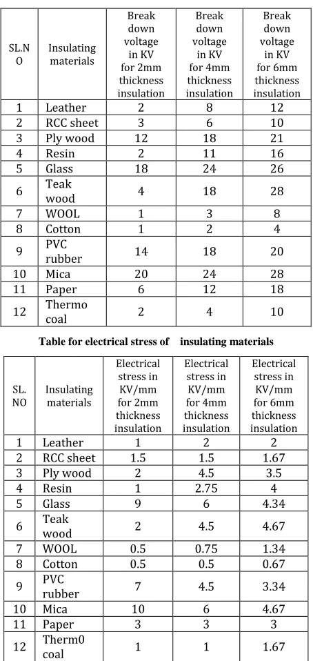
The results are noted and tabulated in table (1) the corresponding electrical stress is calculated and tabulated in table (2). Table (3) shows the tabulation of breakdown voltage and corresponding electrical stress at various distances using air as insulator with same experimental setupThe Tabular Column For Breakdown Voltage Of Solid Insulating Materials
SL.N
O Insulating materials
Break down voltage
in KV for 2mm thickness insulation
Break down voltage
in KV for 4mm thickness insulation
Break down voltage
in KV for 6mm thickness insulation
1 Leather 2 8 12
2 RCC sheet 3 6 10
3 Ply wood 12 18 21
4 Resin 2 11 16
5 Glass 18 24 26
6 Teak wood 4 18 28
7 WOOL 1 3 8
8 Cotton 1 2 4
9 PVC rubber 14 18 20
10 Mica 20 24 28
11 Paper 6 12 18
[image:8.612.324.564.143.260.2]12 Thermo coal 2 4 10
Table for electrical stress of insulating materials
SL.
NO Insulating materials
Electrical stress in KV/mm for 2mm thickness insulation
Electrical stress in
KV/mm for 4mm thickness insulation
Electrical stress in KV/mm for 6mm thickness insulation
1 Leather 1 2 2
2 RCC sheet 1.5 1.5 1.67
3 Ply wood 2 4.5 3.5
4 Resin 1 2.75 4
5 Glass 9 6 4.34
6 Teak wood 2 4.5 4.67
7 WOOL 0.5 0.75 1.34
8 Cotton 0.5 0.5 0.67
9 PVC rubber 7 4.5 3.34
10 Mica 10 6 4.67
11 Paper 3 3 3
12 Therm0 coal 1 1 1.67
Breakdown voltage for air gap
Sl. No
Electric stress in KV/mm
Break down voltage in KV
Electrodes gap distance in mm
1 1.5 3 2
2 1.5 6 4
3 2 12 6
Graphical representation of insulating material which showing the behavior with respect to thickness in mm and BD in kV
5.1 Applications
In transmission and distribution systems
In industries applications
In high voltage lab
Automotive Industries
Capacitors and circuit elements Manufacturing
shock proof appliances
induction ovens , microwave ovens
VI. CONCLUSION
In electrical power system, high voltage (HV) power equipments are mainly subjected with spark over voltage. The over voltage caused by the lighting strokes, switching, determine the safe clearance required for proper insulation level.
0 20 40 60 80 100
2mm 4mm 6mm
leather resin Rcc -sheet plywood
0 50 100
2mm 4mm 6mm
thermocol
paper
mica
pvc rubber
[image:8.612.55.282.227.706.2]International Journal of Emerging Technology and Advanced Engineering
Website: www.ijetae.com (ISSN 2250-2459,ISO 9001:2008 Certified Journal, Volume 5, Issue 10, October 2015)
74
In this study the performance characteristics of air breakdown voltages and electric field behaviors are studied theoretically as well as experimentally by using the standard rod gap method. The breakdown characteristics between the point -point electrodes are observed with variations in electrode arrangements, both in size and spacing. It is concluded that with the increase of gap between rods the breakdown voltage and electric field strength are increased and is inversely proportional to radius. It is concluded that with increase of temperature the maximum electric field and relative air density factor are decreased and with increase of pressure the maximum electric field and relative air density factor are increased. In addition, as the humidity is one of the important factors for measurement of the air breakdown characteristic and it is not changeable during the experiment. We have tested breakdown voltages for various materials and values have been recorded for solid insulating materials. The breakdown voltages of solid insulators are greater than gaseous and liquid insulating materials. From this experiment we can conclude that the solid insulating materials having high breakdown strength and stress.Also we can conclude that the insulating materials like glass, mica, plywood, and teakwood can be used for high voltages applications because of their greater breakdown voltages.
REFERENCES
[1] S. Pillai and R. Hackam, “Electric field and potential distributions for unequal spheres using symmetric and asymmetric applied voltages”, IEEE Transactions on Electrical Insulation, Vol. EI-18,No.5,October1983. [2] E. Kuffel, W. S. Zeangle & J. Kuffel, „High Voltage Engineering
Fundamentals’, published by Butterworth-Heinemann 2nd edition, 2000.
[3] N. K. Kishore, G. S. Punekar, H. S. Y. Shastry, “Spark over in sphere gaps with alternating voltages and perturbed electric fields”, annual report conference on „Electrical Insulation and Dielectric Phenomena‟, 2009.
[4] M. S. Naidu and V. Kamaraju, „High Voltage Engineering’, published by Tata McGrawHill 3rd edition, 2004.
[5] J. H. Colete and J. V. Merwe ,“The breakdown electric field between two conducting spheres by the method of images” IEEE trans on education, Vol.41, No.2, May 1998.
[6] Y. Nishikori, S. Kojima, and T. Kouno, “A study of the field utilization factor and the maximum electric field at spark over of the standard sphere gaps”, Translated from Denki Gakkai Ronbunshi, Vol.21-B, No.3, March 2001.
[7] C. L. Wadhwa, „High Voltage Engineering‟, published by New Age International (P) Limited, 2nd edition 2007.
[8] S. Phontusa and S. Chotigo “The proposed humidity correction factor of positive dc breakdown voltage of sphere-sphere gap at h/δ lower than 13 g/m³”, 2nd IEEE International Conference on Power and Energy (PECon 08), Johor Baharu, Malaysia, December 1-3, 2008.
[9] J. B. Nah. kang, Y. D. Chung, M. C. Ahn, D. K. Bae and T. K. Ko, “Study on the breakdown voltage characterization of insulation gases for developing a high voltage superconducting apparatus”, IEEE Transactions on Applied Superconductivity, Vol.20, No.3, June 2010.
[10] IEEE Standard Technique for High Voltage Testing, IEEE-std. 4-1995, New York 1995.
[11] Rakosh Das Begamudre, „Extra High Voltage AC Transmission Engineering‟, published by New Age International (P) Limited, 3rd edition 2006.
[12] http://home.earthlink.net/~jimlux/hv/sphgap.htm.
[13] Simulation of air breakdown mechanism using different electrodes Srikant, A and Pradhan, S (2011) Simulation of air breakdown mechanism using different electrodes. BTech thesis
[14] measurement of air breakdown voltage and electric field using standad sphere gap method
[15] breakdown of liquid and solid insulation
[16] effect of field utilization factor on air breakdown level under impulse lightning in point-sphere electrode system
Authors:
Mr. N. Lakshmipathy has been teaching profession for the last 17 years. A graduate in B.E (Electrical) and completed M.E (Power electronics) from
University Vesvesvaraya College
Engineering, Bangalore (U.V.C.E). I am working as an Assistant Professor in department of Electrical and Electronics Engineering, Dr. TTIT, KGF. My research areas are high voltage Engineering and insulation, Power Electronics and Illumination design for outdoor applications.
Mrs.Umadevisreedhar received B.E
degree (Electrical & Electronics
Engineering) in Golden Valley Institute of Technology, K.G.F in 2000 under Bangalore University and M. E (power electronics & industrial drives) from sathyabhama university in 2006.
I am currently working as an Assistant Professor in the Department of Electrical Engineering, Dr. TTIT, KGF. My research areas are high voltage Engineering and insulation.
Mr. Somashekar. B received B.E degree (Electrical & Electronics Engineering)
from Golden Valley Institute of
Technology, K.G.F in 1998 under Bangalore University and M. Tech (VLSI & Embedded Systems) from BMS VTURC, VTU in 2009.