International Journal of Emerging Technology and Advanced Engineering
Website: www.ijetae.com (ISSN 2250-2459,ISO 9001:2008 Certified Journal, Volume 4, Issue 9, September 2014)
523
Implementation of Lossless Image Compression Using FPGA
Mugdha Almelkar
1, Dr. S. T. Gandhe
21
Electronics and Telecommunication, Gokhale Education Society’s College of Engineering, Nashik, India
2Principal, Sandip Institute of Technology & Research Centre, Nashik, India
Abstract—This work represents hardware implementation of Lempel Ziv algorithm for lossless image compression. In this paper, hardware-based encoder and decoder have been used. In the proposed system Altera DE-I Board have been used for implementation of an image compression algorithm. The architecture of compression and decompression algorithm design has been created using the hardware description language (VHDL) in Quartus II 9.0. For the processor the supporting software has been written in C is developed. Altera NIOS II 9.0 embedded processor system has been used to perform all hardware interaction tasks necessary on the DE-I board. The custom hardware have been constructed as elements inside the NIOS II system. The experimental results are checked with medical images, stock exchange images, geostationary images and standard images. For the complete analysis, qualitative measures viz. PSNR (peak signal to noise ratio), MSE (Mean square error) and CR (Compression ratio) are calculated. The proposed LZW algorithm on hardware keeps very significant PSNR, lowest MSE.
Keywords – Data compression, Field programmable gate arrays, Image compression, Compression Ratio, MSE
I. INTRODUCTION
Image compression is an application of data compression that encodes the original image with few bits. The objective of image compression is to reduce the redundancy of the image and to store or transmit data in an efficient form.
Image compression is an important topic in medical, business, industrial, and academic applications. Organization of large data can involve substantial overhead in computational complexity, storage, and data processing. Access speeds for storage mediums are inversely proportional to size. Through data compression, such tasks can be optimized. Now the focus has shifted to reconfigurable hardware to implement the image compression algorithm to increase its efficiency and consequently reduce the cost of this technique. Thus the image compression algorithm is implemented with Field Programmable Gate Array. A substantial research is reported in this area.
A. Lossy and Lossless Compression
By using Lossless data compression scheme the exact original data can be reconstructed from the compressed data. This can be different than lossy data compression, which cannot allow the exact original data to be reconstructed from the compressed data. Lossless data compression is used in many applications where minor changes in reconstructed image are also not tolerable. For example, it is used in the medical image compression, Satellite image compression and images which show statistical data. It is also often used as an element in Lossy image compression technologies.
Composite document images may be composed of text, graphics and photographs and may be stored in gray scale or color format. When such documents are compressed without any information loss, they present a challenge, because the chosen compression method should perform well in regions with text or graphics and in regions with photographic content. Lossless compression algorithms have received increasing attention in the past decade.
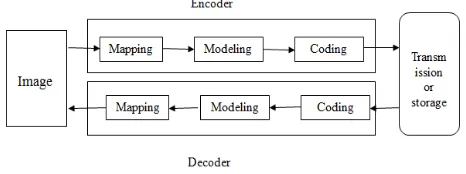
[image:1.612.328.561.529.616.2]An image is a two dimensional signal processed by the human visual system. The signals representing images are usually in analog form. However, for processing, storage and transmission by computer applications, they are converted from analog to digital form. The digital image is represented by the matrix of digits denoting the light intensity of each picture element named pixel. The basic model of lossless image compression is as shown in Fig.1.
Fig. 1 Basic Model for lossless image compression
International Journal of Emerging Technology and Advanced Engineering
Website: www.ijetae.com (ISSN 2250-2459,ISO 9001:2008 Certified Journal, Volume 4, Issue 9, September 2014)
524
The decoder then receives the encoded series of bits and decodes it to form the decoded image. If the total data size of the bit stream is less than the total data size of the original image, then this is called image compression.
Mapping stage is less correlated with the original data. It can be a simple process such as replacing each pixel with the difference between the current and previous pixel (difference mapping), although more complex mapping often yield better results. It changes the statistical properties of the pixel data. This makes data to be encoded closer to being independent, identically distributed and therefore closes to the kind of data that can be efficiently coded by the traditional symbol coding techniques.
The modeling stage attempts to characterize the statistical properties of the mapped image data. It attempts to provide accurate probability estimates to the coding stage, and may even slightly alter the mapped data. By being mindful of higher order correlations, the modeling stage can go beyond the memory less source model and can provide better compression than would be apparent from measuring the entropy of the mapped image data.
The symbol coding stage aims to store the mapped pixel efficiently, making use of probability estimates from the modeling stage. Symbol coders are also sometimes called statistical coders because they use source statistics for efficient representation and entropy coders because they aim to represent data using no more storage than allowed by the entropy of the data. Coding schemes take a sequence of symbols from an input alphabet and produce code words using an output alphabet. They aim to produce a code with the minimum average code word length. The decoding process can be asymmetric with the encoding process, caused by the coding stage’s dependence on the modeling stage.
B. Types of Lossless image Compression
Run Length Encoding Algorithm
Run Length Encoding is the simplest of the data compression algorithms. The repeated sequences of symbols are identified as runs and the others are identified as non runs in this algorithm. This algorithm deals with redundancy [1]. It checks whether there are any repeating symbols or not, and is based on those redundancies and their length. This algorithm identifies the runs of the source file, and records the symbol and the length of each run. The Run Length Encoding algorithm uses those runs to compress the original source file while keeping all the non-runs without using for the compression process. For example, for the Input stream “AAABBCCCCD” the Output will be “3A2B4C1D”.
Huffman Encoding
Huffman Encoding Algorithms use the probability of the alphabet of the source to create the code words for symbols. The frequency of all the characters of the input is calculated to find out the probability distribution. According to the probabilities, the code words are given. Shorter code words are given for higher probabilities and longer code words are given for smaller probabilities. For this task a binary tree is created using the symbols as leaves according to their probabilities and paths of those are taken as the code words. Static Huffman Algorithms and Adaptive Huffman Algorithms are the two types of Huffman Encoding. Static Huffman Algorithms calculate the frequencies first and then create a common tree for both the compression and decompression processes [1]. The Adaptive Huffman algorithms develop the tree while calculating the frequencies and there will be two trees in both the processes.
In this algorithm the symbols with a higher frequency are expressed using shorter encodings than symbols which occur less frequently and the two symbols that occur less frequently will have the same length.
The Shannon Fano Algorithm
This is modified Static Huffman Coding algorithm. The only difference is in the creation of the code word. All the other processes are equivalent to the above mentioned Huffman Encoding Algorithm. Shannon Fano coding, named after Claude Elwood Shannon and Robert Fano, is a technique for constructing a prefix code based on a set of symbols and their probabilities. But it does not achieve the lowest possible expected code word length like Huffman coding.
Arithmetic Encoding
International Journal of Emerging Technology and Advanced Engineering
Website: www.ijetae.com (ISSN 2250-2459,ISO 9001:2008 Certified Journal, Volume 4, Issue 9, September 2014)
525
Lastly a number should be taken from the final sub range as the output of the encoding process. This will be a fraction in that sub range. Therefore, the entire source message can be represented using a fraction. To decode the encoded message, the number of characters of the source message and the probability distribution is needed.
The Lempel Zev Welch Algorithm
This is a dictionary based compression algorithm which is based on a dictionary instead of a statistical model [1]. A dictionary is a set of possible words of a language, and is stored in a table and used the indexes of entries to represent larger and iterating dictionary words. In the compression process, those index values are used instead of repeating string patterns. The dictionary is created dynamically in the compression process and decompression process. So there is no need to transfer it with the encoded message for decompressing. Therefore, this algorithm is an adaptive compression algorithm.
Abraham Lempel, Jacob Ziv and Terry Welchproposed Lempel-Ziv-Welch (LZW) a universal lossless data compression algorithm in 1984[2]. Welch proposed LZW algorithm which adapts to the type of data being processed. This algorithm gives noiseless compression that is decompressed data is an exact replica of input data .Data compression described by this algorithm is the reversible process. This proposed algorithm focused on both text and numerical data [3]. Komma et.al compared different data compression schemes for medical image compression and suitability of the same for volumetric datasets. The study focused on LZW gives a better compression ratio with respect to other compression schemes [4-7].From the above discussion it can be observed that LZW is very effectively used for compressing the images.
LZW compression works best for files containing lots of repetitive data. This is often the case with text and monochrome images. Files that are compressed but that do not contain any repetitive information at all can even grow bigger. LZW places longer and longer repeated entries into a dictionary. This algorithm basically used in medical and satellite image processing as these fields required lossless data compression. The proposed algorithm is implemented on FPGA for different types of images. Different error parameters like reconstruction error, Mean square error are calculated. The hardware can be customized to the compression algorithm. In this paper an FPGA is used for implementation of a codec. FPGA supports flexibility to make changes and tunings of the algorithm since FPGA-based designs are easily modified.
This paper is organized as follows. The next section, section II describes Literature Survey. In section III Proposed scheme is described.
In section IV Design featured of the proposed scheme is described. FPGA implementation with LZW algorithm for image compression is explained in this section. FPGA implementation is described in section V. Section VI describes the error metrics PSNR, MSE and CR with their formulas. In Section VII results are reported on the operation of the coding algorithm on test images and the decoding algorithm on the resultant compressed files. The compression ratio is calculated from actual compressed file sizes and mean squared error or PSNR from the reconstructed images given by the decoding algorithm. Some reconstructed images are also displayed. These results are put into perspective by comparison to previous work. The conclusion of the paper is in Section VIII.
II. LITERATURE SURVEY
Yu-Ting Pai, Fan-Chieh Cheng, Shu-Ping Lu, and Shanq-Jang Ruan were proposed a technique in “Sub-Trees Modification of Huffman Coding for Stuffing Bits Reduction and Efficient NRZI Data Transmission”. They mainly focused on the data transmission and multimedia compression and considered this problem as the encoding of compression and transmission to develop a low bit rate transmission scheme based on Huffman encoding [15]. The proposed method could balance “0” and “1” bits by analyzing the probability of the mismatch in the typical Huffman tree. Moreover, the proposed method also modified the transitional tree under the same compression ratio. Experimental results have showed that the proposed method could reduce the stuffing bits to 51.13% of standard JPEG compression.
International Journal of Emerging Technology and Advanced Engineering
Website: www.ijetae.com (ISSN 2250-2459,ISO 9001:2008 Certified Journal, Volume 4, Issue 9, September 2014)
526
Data compression has been playing an important role in the areas of data transmission. Many great contributions have been made in this area, such as Huffman coding, LZW algorithm, run length coding, and so on. These methods only focus on the data compression. On the other hand, it is very important for us to encrypt our data to against malicious theft and attack during transmission. A novel algorithm named Swapped Huffman code Table (SHT algorithm) which has joined compression and encryption based on the Huffman coding and LZW. This technique was proposed in “Enhanced Huffman Coding with Encryption for Wireless Data Broadcasting System” by Kuo-Kun Tseng, JunMin Jiang, Jeng-Shyang Pan, Ling Ling Tang, Chih-Yu Hsu, and Chih-Cheng Chen [6].
From the above Literature survey we conclude that LZW is very effectively used for compressing the images in a different way.
III. PROPOSED SCHEME
This paper proposes a compression technique using the Lempel Ziv coding to compress image. To recover the image data decompress the image data by Lempel Ziv decoding technique. LZW algorithm is a universal compression algorithms published by Welch in 1984 as an improved implementation of the LZ78 algorithm published by Lemple and Ziv in 1978. The LZW algorithm is organized string table, which maps strings of input characters into codes. The LZW string table has a prefix property in that for every string in the table its prefix string is also in the table.
A. Lzw encoding :
A high level view of the encoding algorithm is shown here [4], [1]:
1.Initialize the dictionary to contain all strings of length one.
2.Find the longest string W in the dictionary that matches the current input.
3.Emit the dictionary index for W to output and remove W from the input.
4.Add W followed by the next symbol in the input to the dictionary.
5.Go to Step 2.
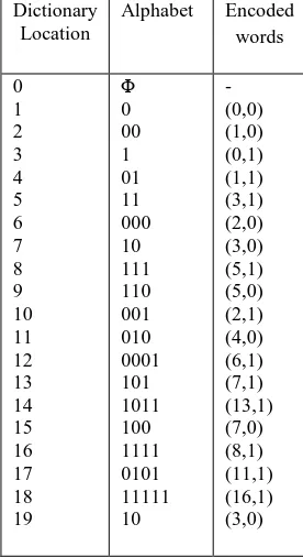
The input code words are
[image:4.612.374.512.147.400.2]00010111000101111100010100001101101110011110101 1111110 and the Lzw dictionary for above is represented as Table I. Table I Lzw Dictionary Dictionary Location Alphabet Encoded words 0 1 2 3 4 5 6 7 8 9 10 11 12 13 14 15 16 17 18 19 Φ 0 00 1 01 11 000 10 111 110 001 010 0001 101 1011 100 1111 0101 11111 10 - (0,0) (1,0) (0,1) (1,1) (3,1) (2,0) (3,0) (5,1) (5,0) (2,1) (4,0) (6,1) (7,1) (13,1) (7,0) (8,1) (11,1) (16,1) (3,0)
and the final encoded values are
(0,0),(1,0),(0,1),(1,1),(3,1),(2,0),(3,0),(5,1),(5,0),(2,1),(4,0), (6,1),(7,1),(13,1),(7,0),(8,1),(11,1),(16,1),(3,0).
B. Lzw Decoding:
The decoding algorithm works as follows.
1. Reading a value from the encoded input and outputting the corresponding string from the initialized dictionary.
2. At the same time it obtains the next value from the input, and adds to the dictionary the concatenation of the string just output and the first character of the string obtained by decoding the next input value. 3. The decoder then proceeds to the next input value
(which was already read in as the "next value" in the previous pass)
4. Go to step 1 until there is no more input, at which point the final input value is decoded without any more additions to the dictionary [5].
5. The result is the concatenated. Decompressed code word is
International Journal of Emerging Technology and Advanced Engineering
Website: www.ijetae.com (ISSN 2250-2459,ISO 9001:2008 Certified Journal, Volume 4, Issue 9, September 2014)
527
IV. DESIGN FEATURES OF PROPOSED SYSTEM
A. FPGA Configuration
[image:5.612.54.283.239.356.2]An FPGA configuration determines the functionality of the FPGA device. An FPGA device is configured by loading a configuration bit-stream into its internal configuration memory. An internal controller manages the configuration memory as well as the configuration data transfer via the I/O interface as shown in Fig.2
Fig 2. FPGA-based embedded system architecture
B. FPGA DE I Board
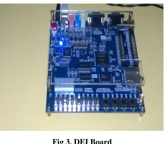
An FPGA configuration determines the functionality of the FPGA device. The DE1 board is as shown in Fig.3. LZW algorithm is implemented on Altera DE 1 kit.
Fig 3. DEI Board
The following hardware is provided on the DE1 board: • Altera Cyclone II 2C20 FPGA device
• Altera Serial Configuration device – EPCS4
• USB Blaster (on board) for programming and user API control; both JTAG and Active Serial
• (AS) programming modes are supported • 512-Kbyte SRAM
• 8-Mbyte SDRAM • 4-Mbyte Flash memory • SD Card socket
• 50-MHz oscillator, 27-MHz oscillator and 24-MHz oscillator for clock sources
• 24-bit CD-quality audio CODEC with in, line-out, and microphone-in jacks
Cyclone series FPGAs are used in DE1 kit which is the industry's lowest cost, lowest power FPGAs, ideal for high-volume, cost-sensitive applications. Use a Cyclone series FPGA alone, as a digital signal processor, or as a cost-effective embedded processing solution. Cyclone series FPGAs offer a wide range of density, memory, embedded multiplier, and packaging options.
V. FPGAIMPLEMENTATION
An FPGA device is configured by loading a configuration bit-stream into its internal configuration memory. An internal controller manages the configuration memory as well as the configuration data transfer via the I/O interface. Fig.3 shows the major data paths of the implementation. DE1 board is used for implementation of image compression on FPGA. The image file is converted to text file as FPGA can understand digital values. This text file is given as an input file for FPGA kit. This file is stored in SDRAM.
The program for kit is stored in Flash memory. The output text file is stored in SDRAM. The hardware for the system is created using the Quartus II and SOPC (System on a Programmable Chip) builder software. In Quartus II SOPC builder is used as a system development tool for creating systems including processors, peripherals, and memories. The steps for implementation of image compression on FPGA are as follows.
i. The image file is converted to text file as FPGA can understand digital values.
ii. This text file is given as a input file for FPGA kit. iii. This file is stored in SRAM.
iv. The program for kit is stored in Flash memory. v. The output text file is stored in DRAM.
vi. The hardware architecture has been built using Quartus II.
vii. The Compression and Decompression algorithm is implemented using NIOS II.
VI. ERROR METRICS THE COMPRESSION RATIO IS DEFINED AS FOLLOWS:
Cr =
(i)
[image:5.612.87.250.435.577.2]International Journal of Emerging Technology and Advanced Engineering
Website: www.ijetae.com (ISSN 2250-2459,ISO 9001:2008 Certified Journal, Volume 4, Issue 9, September 2014)
528
In order to evaluate the performance of the image compression coding, it is necessary to define a measurement that can estimate the difference between the original image and the decoded image. Two common used measurements are the Mean Square Error (MSE) and the Peak Signal to Noise Ratio (PSNR) .Most image compression systems are designed to minimize the MSE and maximize the PSNR.
The MSE metric is computed by averaging the squared intensity difference of reconstructed image ý and the original image y. PSNR can be calculated mathematically,
MSE= 1/MN [ yK- ýK ]2 (ii)
For an image with M rows and N columns PSNR is defined
as PSNR = 10log10 [2552/ MSE] (db) (iii) In the above equation 255 represents maximum gray level value in an 8 bit image.
VII. RESULT ANALYSIS
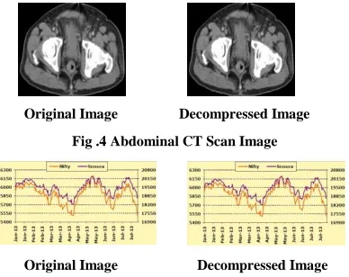
The quality of an image can be evaluated based on the subjective and objective fidelity picture quality measures. Subjective fidelity is normally based on the visual information or perceptive ability while the objective fidelity measures are totally numerical based on computable distortion measures. Mean squared error (MSE) and Peak Signal to Noise Ratio (PSNR) are the most common measures of picture quality, despite the fact that they are not adequate as perceptually meaningful measures. The original image and decompressed image of Abdominal CT Scan and Sensex image are shown in Fig.4 and Fig.5 respectively .
[image:6.612.316.572.212.533.2]
Original Image Decompressed Image
Fig .4 Abdominal CT Scan Image
Original Image Decompressed Image
Fig .5 Sensex Image
The MSE between the target image and reconstructed image should be as small as possible so that the reconstructed image quality will be near to the target image, in ideal cases the mean square error is zero for decompression. Calculation of all the error metrics are shown in Table II and Table III.
Table II
Calculation of all the metrics for Abdominal CT Scan Image
Image Original Image
Compress ed Image
CR PSN R
MS E
Reconstructi on Error
16x16 2560 777 1:0.30 inf 0 0
32x32 10240 2098 1:0.204 inf 0 0
64x64 40960 6268 1:0.153 inf 0 0
128x128 163840 21663 1:0.132 inf 0 0
Table III
Calculation of all the metrics for Sensex graphical image
Image Original Image
Compress ed Image
CR PSN R
MS E
Reconstructi on Error
16x16 2560 675 1:0.263 6
inf 0 0
32x32 10240 1945 1:0.189 9
inf 0 0
64x64 40960 5695 1:0.139 inf 0 0
128x128 163840 17014 1:0.103 inf 0 0
VIII. CONCLUSION
Based on the above evaluations concerning the usage of LZW lossless image compression on different images, acceptable results are generated. This algorithm is used for lossless image compression which is used for medical image, satellite image processing and statistical data representation. So in the result analysis medical image and sensex image are considered. The metrics that is PSNR, MSE for these images are ideal means the reconstructed image is as same as original and CR tends to vary for different image sizes and different input images based on their content.
[image:6.612.71.265.519.673.2]International Journal of Emerging Technology and Advanced Engineering
Website: www.ijetae.com (ISSN 2250-2459,ISO 9001:2008 Certified Journal, Volume 4, Issue 9, September 2014)
529
The above presented compression and decompression technique is very efficient technique for compressing the image to a great extent. The future work more focus shall be on improvement of compression ratio.
REFERENCES
[1] BelloYu-Ting Pai, Fan-Chieh Cheng, Shu-Ping Lu, and Shanq-Jang Ruan, “Sub-Trees Modification of Huffman Coding for Stuffing Bits Reduction and Efficient NRZI Data Transmission”, IEEE Transactions on Broadcasting, vol. 58, no. 2, June 2012.
[2] S.B. Choi and M.H. Lee, “High speed pattern matching for a fast Huffman decoder,” IEEE Trans. Consum. Electron., vol. 41, no. 1, pp. 97–103, Feb. 1995.
[3] Huang-Chih Kuo and Youn-Long Lin,”A Hybrid Algorithm for Effective Lossless Compression of Video Display Frames”, IEEE Transactions on Multimedia, vol.14, no.13, June 2012.
[4] Introduction to Data Compression, Khalid Sayood, Ed Fox (Editor),March 2000.
[5] C.Saravanan and M.Surendra “Enhancing efficiency of Huffman Coding using Lempel Ziv Coding for image compression”, IJSCE January 2013
[6] T. A. Welch. A technique for high-performance data compression. Com-puter, 17(6):8-19, 1984.
[7] Mamta Sharma, “Compression Using Huffman Coding”, ternational Journal of Computer Science and Network Security, Vol.10, No.5, May 2010.
[8] Sindhu M, RajkamalR“Images and Its Compression Techniques A Review”International Journal of Recent Trends in Engineering, Vol 2, No.4, November 2009.