Voltage rise due to inter connection of embedded generators to distribution network
6
0
0
Full text
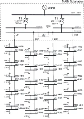
(2) 434. J SCI IND RES VOL 69 JUNE 2010. Fig. 1—Single line diagram of generic distribution network. 132/11kV, z=12.0% step down transformer connected in parallel equipped with OLTCs. Main station 11 kV system consisted of three bus bars (Main-L, Main-R and Reserve), coupled by bus section (CB30) and coupler circuit breaker (CB34). Secondary side of transformer 1 (T1) was connected to left hand side of 11 kV Main bus bar while transformer 2 (T2) was connected to 11 kV Reserve bus bar. Bus bar (11 kV) supplies to four 11 kV-outgoing feeders, and each 11 kV feeder supplies to five LV distribution substations, each of which consisted of two bus bars (500 kVA load at each bus). All loads were modeled at constant 465.0 kW and 184.0 kVAr (PQ) with 0.93 lagging power factor (PF). Loads were assumed uniformly distributed along outgoing feeder to each bus bar. Gas district cooling (GDC) co-generation. power plant consisted of one unit of synchronous generator rated at 11kV, 5MVA at 0.8 lagging PF. Results and Discussion Test studies utilized voltage limits for an 11 kV voltage level (±5.0%). Simulations were focused on detecting network’s operating conditions to ensure operation within nominal voltage limits. Various scenarios were created with different parameters (EG penetration level, loading of network, automatic voltage control (AVC) relay set point at primary substation, power factor of network loading and various operating mode of EG). All DG’s considered in this study were fuelled by non conventional sources..
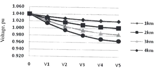
(3) MEKHILEF et al: VOLTAGE RISE DUE TO INTER-CONNECTION OF EMBEDDED GENERATORS. 435. Voltage, pu. Voltage profile (offline, peak load). Fig. 2—Network voltage profile with Main substation voltage at 1.05 pu. For carrying out simulations, load flow analysis was performed to ensure power flow on 11 kV feeders within appropriate transfer capabilities of associated cables. No overloading was anticipated if operated in normal arrangement (with appropriate off point). In order to ensure that extreme feeders do not experience low voltage, multiple simulations were carried out with Main substation 11 kV bus bar voltage fixed at 1.00 pu, 1.03 pu and 1.05 pu. Load flow study was performed again using best set point at Main substation, derived from earlier study. Voltage profile for feeder 1 and feeder 4 was monitored and recorded. Various scenarios were analyzed for the following: i) Assessing effect on voltage profile by varying EG penetration level and PF for peak and light loading conditions; ii) Assessing effect on voltage profile by changing settings of taps on Main substation transformers; and iii) Assessing effect on voltage profile by varying load PF and operating modes of EG. Scenario 1: Base Case. Base case study, which was performed prior to interconnection of EG plant to generate voltage under normal circumstances, gives best set point for Main substation voltage to ensure voltage at feeder with longest length remaining within statutory limit. Study was performed for peak load to represent worst case for voltage drop along cable as compared to light load. Without connection of EG plant, set point of Main substation AVR relay was set at 1.05pu. It was possible to maintain voltages at all buses above 95% (Fig. 2). Scenario 2: EG Operating at Fixed PF Mode. A 5.0 MVA EG plant (Fig. 3) operating at node M43-MBB (weak feeder) operating at 0.85 leading PF (Fig. 4a) and 0.85 lagging PF (Fig. 4b) was connected to the system. Voltage profile of associated 11 kV feeder was. investigated. Voltage rises for weak feeder during light load with EG plant operating at leading PF (Fig. 4a) whereby voltage at V2, V3, V4 and V5 exceed 1.05 pu. EG operating at lagging PF (Fig. 4b) increases voltage magnitude at point of common coupling (PCC) above 1.05 pu during peak load as compared to plant operating at leading PF (Fig. 4a). Feeder 4 was able to absorb additional power from EG plant operating at leading PF only during peak load without causing bus voltages at feeder stay above upper limit (1.05 pu). Thus 5 MVA generator on node M43-MBB operating at constant 0.85 lagging PF or leading PF during light load increases voltage above upper limit of 1.05 pu. Scenario 3: EG Operating at Voltage Control Mode (PV). To investigate network voltage profile when operating at PV mode, magnitude of generator terminal voltage was kept constant by generator AVR. A 5.0 MVA EG plant operating in PV mode was connected at node M43-MBB and terminal voltage at PCC was set at 1.00 pu (Fig. 5a) and 1.03 pu (Fig. 5b). EG plant causes voltage rise at PCC far above set point of 1.00 pu (Fig. 5a). As such, EG plant absorbs reactive power in order to achieve target voltage of 1.00 pu. Voltage for feeder 4 during light load at node M42-MBB (V2), M43-MBB (V3), M44-MBB (V4) and M45-MBB (V5) increased above upper limit of 1.05 pu. Similar voltage rise was observed with set point of 1.03 pu (Fig. 5b) at PCC. With EG plant’s AVC set at 1.00 pu and 1.03pu at PCC, voltage rise for all buses at feeder 4 were well below 1.05 pu during peak load only. EG plant operating at voltage control with voltage setting lower than voltage at PCC caused generator operating at leading reactive power hence consuming reactive power. Network PF was deteriorated. This is not a desired operation mode because when EG plant.
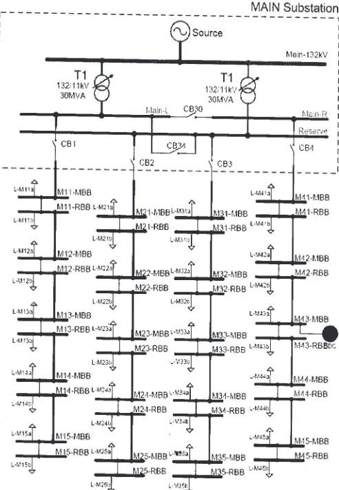
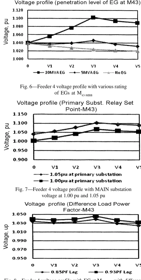
(4) 436. J SCI IND RES VOL 69 JUNE 2010. Fig. 3—Network connection used for Scenario 2. draws reactive power, higher current flowing on feeder results in stress on cable/line, which operates at very high load. Besides, stresses to cable/line, higher current flow also caused higher voltage drop and more losses incurred. Scenario 4: Penetration Level of EG Plant. Low penetration is described by a penetration factor of < 0.30. High penetration is described by a penetration factor of < 0.30. EG plant rated at 5 MVA and 10 MVA with penetration factor of 1.00 and 2.00 was chosen for simulation. Result for connection of 5.0 MVA and 10 MVA EG plant operating at 1 PF at M43-MBB during peak load (Fig. 6) showed that voltage increases at PCC to 1.05 pu and 1.10 pu respectively for 5 MVA and 10 MVA EG plant connected at a weak feeder. It showed reverse in power flow along line from EG plant towards Main substation (Scenario 1). This study enabled determination of EG capacity that can be connected to. feeder. Increasing generation from 5 MVA (almost identical to feeder loading) to 10 MVA reversed flow of power along the line, from embedded generator towards Main substation. Voltage at PCC increased to 1.10 pu allowing power to be exported in both directions. When 10 MVA EG plant connected, voltages at V2, V3, V4 and V5 rise above upper limit of 1.05 pu. Scenario 5: Automatic Voltage Control (AVC) Relay Set Point. Connection of EG plant complicates existing voltage regulating equipment. It is assumed that distribution network operators (DNO) do not actively manage on load tap changer (OLTC). Exchange of information such as voltage and real and reactive power between PCC and Main substation was not available. Hence, Main substation AVR relay was unable to use this additional information to determine desired set point. Scenario 5 investigates effect of existing voltage control equipment on voltage profile of network with high penetration of.
(5) MEKHILEF et al: VOLTAGE RISE DUE TO INTER-CONNECTION OF EMBEDDED GENERATORS. 437. Fig. 6—Feeder 4 voltage profile with various rating of EGs at M43-MBB. Fig. 4—Feeder 4 voltage profile with EG operating at: a) 0.85 leading power factor; and b) 0.85 lagging power factor Fig. 7—Feeder 4 voltage profile with MAIN substation voltage at 1.00 pu and 1.05 pu. Fig. 8—Feeder 4 voltage profile with EG at M43-MBB with different network power factor. Fig. 5—Feeder 4 voltage profile with EG terminal voltage at: a) 1.00 pu; b) 1.03 pu. EG. Simulation network was a repetition of Scenario 4, by controlling secondary winding of 132/11kV transformer at 1.00 pu and 1.05 pu.. Results (Fig. 7) are shown with connection of 10 MVA EG plant (operating at 1 PF) at M43-MBB during peak load and Main substation 11 kV bus bar voltage set at 1.00 pu and 1.05 pu. For this scenario, effectiveness of existing voltage control equipment, OLTC, was investigated on 132kV/11kV transformer at different voltage set point. Voltages at V2, V3, V4 and V5 rise above upper limit (1.05 pu) with AVC relay voltage setting of 1.05 pu. Node voltages for V3-MBB, V4-MBB and V5-MBB also increased above upper limit (1.05 pu) even though AVC relay voltage set point was changed to 1.00 pu..
(6) 438. J SCI IND RES VOL 69 JUNE 2010. Scenario 6: Change of Load Power Factor. It is desirable to supply distribution network load in 1 PF. This is not achievable because most of the load and distribution equipments are inductive. PF of modeled system was at 0.93 lagging. Scenario 6 investigated effect on network voltage profile by changing load PF to 0.85 lagging. Results (Fig. 8) are shown with connection of 5.0 MVA EG plant operating at 1 PF at M43-MBB during peak load with PF of 0.93 lagging and 0.85 lagging. In this scenario, load on 11 kV feeder was assumed to have a PF of 0.85 (lagging), lowest allowable PF by Tenaga Nasional Berhad (TNB). When load PF in 11 kV feeder was changed from 0.93 lagging to 0.85 lagging (Fig. 8), there was an associated change in reactive power flow. Voltage magnitude was reduced but with very small difference. Again, voltage drop was experienced at node M43-MBB due to longer cable length. Conclusions Introduction of EG at distribution network caused voltage rise at PCC leading to customer voltages out of allowable range. Effect of voltage rise during peak load was less severe as compared to light load. As distance from Main substation increased, capacity of EG was reduced. Operating EG units with a lagging PF resulted in reactive power being supplied to the network, which may cause an increase in local network voltage. On the other hand, operation with a leading PF had opposite effect. Hence, it is possible to control network voltage magnitude by adjusting operating PF of EG. Sizing and location on EG plants were found to be among the factors needed to accommodate EG into distribution network. Increase of voltage at PCC was proportionate to the amount of real and reactive power injected to network. Hence, as rule of thumb, real power that can be exported by EG should be equivalent to loading of relevant feeders. Actively managing voltage control schemes at Main substations enables operator to reduce restrictions imposed by voltage rise on network. Through careful design of. connection arrangement, DNO can ensure new plant connection without causing problems. In some cases, EG plants can enhance network performance. References 1. Daly P A & Morrison J, Understanding the potential benefits of distributed generation on power delivery systems, in Proc Rural Electric Power Conf (IEEE Explorer Press, Little Rock, AR, USA) 2001, A2.1-A2.13. 2 Driesen J & Belmans R, Distributed generation: Challenges and possible solutions, in Proc Power Eng Soc General Meeting (IEEE Explorer Press, Montreal, Quebec, Canada) 2006, 1-8. 3 Jenkins N, Embedded Generation, Power Eng J, 9 (1995) 145150. 4 Barker P P & Johnson B K, Power system modeling requirements for rotating machine interfaced distributed resources, in Proc Power Eng Society Summer Meeting (IEEE Explorer Press, Chicago, IL, USA) 2002, 161-166. 5 Ahmed M A & István E, Impact of distributed generation on the stability of electrical power systems, in IEEE Proc Power Eng Society General Meeting (IEEE Explorer Press, San Francisco, California, USA) 2005, 1056-1063. 6 Jenkins N & Strbac G, Effects of small embedded generation on power quality, in Proc IEE Colloqium on Issues in Power Quality (IEEE Explorer Press, Warwick, UK) 1995, 1-6. 7 Slootweg J G & Kling W L, Impacts of distributed generation on power system transient stability, in Proc IEEE Power Eng Society Summer Meeting, vol 2 (IEEE Explorer Press, Chicago, IL, USA) 2002, 862-867. 8 Senjyu T, Miyazato Y, Yona A, Urasaki N & Funabashi T, Optimal distribution voltage control and coordination with distributed generation, IEEE Trans Power Delivery, 23 (2008) 1236-1242. 9 Salman S K, The Impact of embedded generation on voltage regulation and losses of distribution network, Proc IEE Colloq, 1996, 1-5. 10 Kojovic & Ljubomir, Impact of DG on voltage regulation, in Proc IEEE Power Eng Society Summer Meeting, vol 1 (IEE Press, UK) 2002, 97-102. 11 Salman S K, Jiang F & Rogers W J S, Investigation of the operating strategies of remotely connected Embedded Generators to help regulating local network voltage, in Proc Int Conf on Opportunities and Advances in International Electric Power Generation (IEEE Explorer Press, Chicago, IL, USA) 1996, 180-185. 12 Nigel C S, David J A & James E M, Use of load control to regulate voltage on distribution networks with embedded generation, IEEE Trans Power system, 17 (2002) 510-515..
(7)
Figure
Related documents
This indicates that commuters with high value of travel time or high schedule delay cost incur higher bottleneck costs at the short-run equilibrium.... We see from the results of
Thus, in addition to thermal comfort and CO 2 measurements (held during occupancy period), the ventilation performance was assessed in terms of air change rates (ACR) and
Dengan demikian jamur yang ditumbuhkan pada media dengan penambahan kitin akan beradaptasi dengan kondisi tersebut sehingga pada saat diujikan terhadap rayap, jamur diduga akan
The internal audit function provides an independent and objective assurance service that is guided by a philosophy of adding value to the operations of the East Bay Regional Park
• Distinguishes generators by size (power rating) and voltage level at grid connection point – stricter rules for larger plants. • The following slides relates to large power
discipline. An investigation or experimental study should be typical of those in which the graduate would participate in an employment situation shortly after graduation. Note:
has not allowed any earned runs in 9.0 innings in Pac-10 action P Mitchell Beacom (R-Fr.) Has logged 13 strikeouts in eight innings, making seven relief appearances this season P
Pangkat berkaitan dengan penggunaan sapaan pada hirarki suatu kelompok kerja seperti atasan dan bawahan. Seseorang yang pangkatnya lebih tinggi dapat menyapa kepada orang yang
