International Journal of Emerging Technology and Advanced Engineering
Website: www.ijetae.com (ISSN 2250-2459, ISO 9001:2008 Certified Journal, Volume 7, Issue 5, May 2017)
177
The Expedition towards
Venus
Dr. Alexander Rubinraut
Schleißheimerstr. 285a, 80809 Munich, Germany
Summary-- A project of an expedition towards planet
Venus, which is carried out in two stages, is considered. At the first stage, a space train, consisting of a locomotive and a tank with working substance, delivers onto Venus orbit the landing capsule with the Venus plane and the Venus rover, as well as the tank-container with liquid hydrogen, which is used subsequently for return of the expedition onto the Earth orbit. At the second stage, space train consists of a locomotive, a tank-container and the habitable capsule, in which three astronauts commit orbital flyby of Venus. To study the upper layers of the atmosphere of Venus, a design of Venus plane has been developed. To study the surface of Venus a design of Venus rover has been developed. For transmission of scientific information from the Venus plane and the Venus rover an orbital space laboratory has been developed. The expedition duration is 50 days , cost – 2 billion dollars.
Keywords-- Venus, space train, landing capsule, Venus
plane, Venus rover, orbital space laboratory
I. INTRODUCTION
The exploration of Venus – the nearest neighbor of our Earth - continues to remain one of priority areas in astronomy and astronautics.
Let us recall the main historical milestones in the research of Venus.
Year 1616 - Galileo Galilei, is the first who studies the planets of the solar system while using the telescope invented by him and when he directs the tube towards Venus, he finds out that it has the phases, which are similar to lunar and therefore it must rotate around the Sun.
Year 1761 Michel Lomonosov observes through telescope how Venus goes through the disk of the Sun and discovers that the planet is surrounded by the atmosphere and the dense clouds of the atmosphere do not permit to examine the surface of Venus using a telescope.
Until the mid-20 century Venus remained the full mystery for astronomers.
Year 1962 One of the first NASA' s spacecrafts „Mariner-2“ probes the atmosphere of Venus and studies the temperature and composition of the atmosphere. It was found out that the atmosphere consists of carbon dioxide and the pressure on the Venus surface in 90 times more than on the surface of the Earth.
The average temperature on the surface of Venus reaches 460ºC
Year 1970 The spacecraft „Venera -7“, which was developed by Georgy Babakin (USSR), performs the landing onto Venus surface. The spacecraft was working during 23 minutes.
Year 1975 With the help of the spacecraft „Venera -9“ the first photos of the planet Venus are obtained.
Year 1989 The international space station “Magellan”, launched from Cape Canaveral, has entered onto elongated orbit around Venus with the approaching up to 295 km.
During a year, with the help of telescope of 3,7 m diameter the mapping of the entire Venus surface was carried out.
On 12th October 1994 the contact with the station was lost. It happened during an attempt of the spacecraft "Magellan" to enter into upper layers of Venus atmosphere. Year 2006. The European spacecraft „Venus Express“ has entered into the lower layers of Venus atmosphere and then had left the atmosphere. The mystery of a giant cloud in the form of letter Y was revealed.
It is time to carry out an expedition to Venus. The project
of such expedition is offered in this article.
The technical basis of the project are patents, technical proposals, calculations and constructive developments, performed by the author in recent years for projects of expeditions towards planets of the solar system.
In year 2014, the project of expedition towards Mars [1] was developed and published. The expedition is carried out using the rocket train, that moves from Earth orbit to Mars orbit. A distinctive feature of the project is that putting of the individual modules of the space train: locomotive, tanks with working substance and takeoff - landing capsule into the circumterrestrial orbit is carried out using carrier rocket “Ariane-5”. Another feature of the project is that at first a preliminary flight is carried out and a tank with working substance, which later is used to return the train into Earth orbit, is delivered into orbit Mars. Owing to this, the duration of the flight shortens in twice.
The space train is set in motion by using the electrorocket magnetoplasma engine of the new design, which was developed by author.
International Journal of Emerging Technology and Advanced Engineering
Website: www.ijetae.com (ISSN 2250-2459, ISO 9001:2008 Certified Journal, Volume 7, Issue 5, May 2017)
178
Application of on-board power plant of new design, consisting of MHD-generator and the turbogenerator, which work together, increases the efficiency of the power plant in twice [3].
In addition, in the project the takeoff-landing capsule was developed, in which the application of cryogenic system and superconducting solenoid makes it possible to protect astronauts from cosmic radiation [3].
When designing this expedition, the possibility of landing astronauts on the surface of Venus was considered.
As it was already mentioned, the conditions for stay of a person on the surface of Venus are extremely unfavorable.
Due to the high temperature (470°) and high atmospheric pressure (90 bar) in order to move along the surface one needs a special spacesuit with a device similar to a deep-sea diving suit .
In addition, it is necessary to use a mobile cooling system lowering the temperature from 470ºС to 20ºС. This is the task of exceptional complexity, which solution is yet not been found. There is also the problem of creation of takeoff capsule for Venus: in addition to overcoming of gravity force when taking off from the surface of Venus, one has to overcome the force of frontal resistance of very dense atmosphere.
For this reasons, this project does not provide to send astronauts on the surface of Venus.
The purpose of the expedition: to accomplish a flying around Venus in the upper layers of its atmosphere and to launch three automatic devices for scientific observations, which remain to constantly operate on Venus.
The first automatic installation should move along the surface of Venus. The second automatic installation should move in the upper layers of atmosphere. The third automatic installation moves along a circular orbit around Venus, as a man-made satellite.
II. THE CONCEPT OF HIGH-SPEED FLIGHT TOWARDS
VENUS
In the capacity of the concept basis, the technique of carrying out the expedition towards Mars, which was proposed in 2013 [3], has been used. In accordance with this technique the expedition to Venus is carried out using the space train, which is set in motion by space locomotive. For creation of reactive traction with the help of magnetoplasma reactive engines, hydrogen, which is stored in tanks-containers in liquid condition, is used.
In order to reduce the time of flight, a tank-container with working substance, which is then used to return to Earth, is preliminary being sent towards orbit of Venus.
So the expedition towards Venus begins with preliminary flight of the space train, which purpose is to deliver towards the orbit of Venus a tank-container for refueling on orbit, as well as landing capsule with the automatic devices, which are sent for a long-term study of the processes occurring at the surface and in the atmosphere of Venus.
Layout of the rocket train for preliminary flight is shown at Fig.1.
Fig. 1
The train consists of a locomotive 1 with electrorocket engines 2, an on-board power installation, as well of three “cars”. The cars 3 and 5 are tank-containers with working substance. The last ”car” 8 is the landing capsule with “ Venus plane” and “Venus rover”. The detailed descriptions of the “Venus plane” and the “Venus rover” are given below. Formation of the space train (Fig. 1) takes place on circumterrestrial orbit. At first the space locomotive 1 is launched, when using the carrier rocket „Delta 4 Heavy“. It should be reminded, that the space locomotive is equipped with four electrorocket engines of magnetoplasma type having the total traction force of 1000 N.
International Journal of Emerging Technology and Advanced Engineering
Website: www.ijetae.com (ISSN 2250-2459, ISO 9001:2008 Certified Journal, Volume 7, Issue 5, May 2017)
179
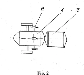
[image:3.612.96.237.308.434.2]After coupling of the space train components by means of docking (Fig. 1), the electric motors 2 of the locomotive are switched on and when reaching of the second space speed the train leaves Earth orbit and begins movement along the calculated trajectory towards Venus. When reaching of Venus, the space train (Fig. 1) enters into its orbit. On Venus orbit, an undocking and a departure between tank-containers 3 and 5 take place (in an automatic mode). The tank-container 5, coupled with the landing capsule, remains on Venus orbit. The space train, consisting of the locomotive 1 and the tank –container, leaves Venus orbit. The electrorocket engines 2 of the locomotive are switched on, and the space train, which is shown at Fig. 2, is heading towards the Earth orbit.
Fig. 2
For the flight from the orbit of Venus to the Earth orbit, the working substance in the amount of half of the tank-container 3 is used.
[image:3.612.60.277.508.644.2]The main flight towards Venus begins from the formation of the space train, shown at Fig.3
Fig. 3
The space locomotive 1, which has returned after the preliminary flight to Venus, moves along the circumterrestrial orbit. The tank-container 3 filled with liquid hydrogen is being launched into this orbit when using rocket Delta 4 Heavy.
With the help of the electrorocket engines 2 the locomotive approaches to the tank-container 3. The last stage the space train formation is the coupling with the habitable capsule 4, which is intended for accommodation of the crew of the expedition towards Venus.
The habitable capsule was developed by the author in year 2013 and the description of its design is given in [3].
The special feature of the design is that in order to create artificial gravity in crew cabin, the habitable capsule 4 rotates in superconducting bearing relative to the horizontal axis.
The habitable capsule (without astronauts) is entered into Earth orbit with the help of carrier rocket „Arian 5“. On the habitable capsule the chemical oxyhydrogen rocket engine 6 is installed. With its help the capsule goes into the orbit of the international space station ISS and goes to a free „moorage” of the station. After that in the automatic mode the taxiing and docking with the moorage is performed. The crew of the expedition, consisting of 3 astronauts is delivered in advance on the station ISS. The astronauts proceed into the cabin inside the capsule 4. With the help of chemical rocket engine 6 the capsule 4 casts off from the moorage of ISS and moves towards orbit of the formed space train. With the help of the docking assembly 5, the habitable capsule 4 is connected to the tank-container 3. Now the space train is ready to the main flight towards Venus.
The expedition towards Venus consists of five stages. The first stage is the achievement of Venus orbit. The second stage is movement along Venus orbit, monitoring and control of the descent and separation of the landing capsule, the starting up of "the Venus plane" and "the Venus rover". Third stage is the launching of a permanent orbital research laboratory. The fourth stage is the flying around Venus in order to observe the movement of the atmosphere and to perform a sensing of its upper layers. The fifth stage - flight from the Venus orbit towards the Earth orbit.
At the first stage the electrorocket engines are switched on and the space train, shown at Fig. 3, begins to gain speed. After reaching of the second space speed train enters into the calculated trajectory of flight.
The calculation of flight trajectory to Venus was performed using the astrodynamic program, which is based on the Newton task solution on the movement of artificial bodies in the gravitational field of the planetary solar system [4]
International Journal of Emerging Technology and Advanced Engineering
Website: www.ijetae.com (ISSN 2250-2459, ISO 9001:2008 Certified Journal, Volume 7, Issue 5, May 2017)
180
Fig.4
Fig. 5
When flying from Earth orbit into the orbit of Venus, the space train travels from point 1' of the Earth orbit to the point 2 of the Venus orbit. It should be reminded, that the angular orbital velocity of Venus movement in 1.7 more than the angular velocity of the Earth movement . It seems like that Earth is “catching up “ Venus, and the Earth position at moment, when the space train goes into Venus orbit, is fixed in point 2. In nine days of the space train movement its speed reaches 150 km/s. The cruise electric rocket engines are being switched off and the train continues to move from point 1 ' to point 2 with constant speed. Half of working substance in the tank-container 3 (fig. 3) has been already used up and the mass of the train has decreased from 60 tons up to 50 tons. After 14 days of flight the braking command is given. The electrorocket engines are being turned around 180 º and are switched on full power. The braking of the train continues 6 days. After twenty days since the beginning of the movement the space train goes into orbit of Venus.
It should be kept in mind, that at Venus orbit at the height of 100 km from its surface, the landing module, connected with the tank-container filled with liquid hydrogen, revolves, which was launched during the preliminary flight.
The space train shown in Fig. 3, performs a maneuver in order to replace the empty tank-container on the full tank. To this purpose, the space train is divided with the help of the docking assemblies 3 and 5. The landing module and the empty tank-container are divided with the help of the docking assembly 5. The locomotive 1 is docking with the full tank-container.
After joining of the tank-container 3 and the locomotive 1, the command is given for approaching, taxiing and docking of the habitable capsule with now already full the tank-container 3. As a result of those operations now the space train (Fig. 3), the separated from it the empty tank-container and the landing capsule are revolving around Venus while being on its orbit.
Astronauts begin to perform works in accordance with the program of the second stage of the expedition. At Fig. 6 the structure of the landing capsule is shown.
Fig. 6
International Journal of Emerging Technology and Advanced Engineering
Website: www.ijetae.com (ISSN 2250-2459, ISO 9001:2008 Certified Journal, Volume 7, Issue 5, May 2017)
181
At the upper part of the module 1 the parachute system 7 is located for braking in the Venus atmosphere.
When the command for descending of the landing capsule is given, the chemical rocket engine 4, which vector of tractive force is directed against movement direction along Venus orbit, is switched on. At decreasing of speed up to 7 m/s the landing capsule loses its weightlessness and under impact of gravity starts to approach the surface of Venus. At a distance of 70 km from the Venus surface, it enters into Venus atmosphere, the density of which gradually increases. The rocket engine 4 controls the change of speed with which the landing capsule enters into the atmosphere.
After giving of the corresponding command, the external casing 8 of the module 1 is automatically removed and the parachute system 7 is being switched on. The parachutes are opening and modules 1 and 2 smoothly descend while passing through the upper layers of Venus atmosphere.
At a height of 50 km, where atmospheric pressure reaches 1 bar, the command is given for the separation of the modules 1 and 2. The separation of the modules is carried out using the cylindrical connection 3. After separation of the modules, the assembling of the Venus plane, which is located in the module 1, is carried out. Now the module 1 is only under impact of gravity, which is balanced by lifting force of the parachute. The module 1 is hanging in the upper layers of Venus atmosphere. The module 2 under impact of gravity force and the chemical rocket engine 4 smoothly moves away off the module 1 heading towards Venus surface.
And now let us consider the structure of the “Venus plane”, which is shown at Fig. 7 and Fig. 8.
III. VENUS PLANE
The „Venus plane” is intended for continuous flight at a height of 50-60 km in the Venus atmosphere in order to transmit the information from “Venus rover” and to control the movement of the “Venus rover” over Venus surface, as well as for the study of the processes occurring in Venus atmosphere.
Aboard of the Venus plane , the equipment for communication and control, as well the instruments for studying of atmospheric flows are being installed.
It should be recalled that multi-year studies, conducted using the space apparatus "Venus Express “ until now have not allowed to identify the causes of occurrence of hurricanes, moving at the speed , which is 50 times faster than the speed of Venus rotation . The Venus plane can help to solve this problem.
The Venus plane operates on the principle of an aircraft, whose wings are covered with semiconductor photovoltaic panels (solar elements). The solar elements produce electricity, being used by electric motor, on which shaft an air propeller, creating the horizontal tractive force, is installed. Nowadays there is a positive experience of implementation of aircrafts using solar cells in the Earth's atmosphere, which was used in designing the Venus plane And at that the working conditions of the Venus plane on solar cells flying in Venus atmosphere are more favorable than for aircraft on solar cell flying in Earth's atmosphere.
It should be reminded that a venusian day lasts 243 days. This allows to flight without installation of a heavy energy storage device - accumulator battery. The Venus plane is equipped with a computerized control system that provides flight of the Venus plane in the zone which is constantly illuminated by the Sun. A distinctive feature of the Venus plane design is that it should be dismountable. The Venus plane in assembled condition is shown at Fig. 7.
Fig. 7
International Journal of Emerging Technology and Advanced Engineering
Website: www.ijetae.com (ISSN 2250-2459, ISO 9001:2008 Certified Journal, Volume 7, Issue 5, May 2017)
182
The assembling of the wings is explained with the help of Fig.8, where in the upper part is shown the wing position in assembled condition after delivery of the Venus plane inside the cylindrical container 19, which serves as the outer casing for the upper module of the landing capsule.
Fig. 8
In order to install the elements of the wing 2 (Fig. 7) in the operating position perpendicular to the horizontal axis, the sliding rods 13 are set, which are fixed on the cylinder 11. The design of the sliding rods 13 executed in the form of concentric cylinders, which are inserted into each other. It is similar to the telescopic antenna of portable receiver.
The sliding rod 13 is connected with stem 14. The stem 14 is located on the extreme panel of the wing 2.The spreading of the wings is carried out using rocket engines 15, which put the module of wing in the position, shown in the lower part of Fig. 8. For stabilization and aerodynamic control of the system of such a modular Venus plane there are empennage with fin 4, stabilizer 3 and elevation rudder 18 (Fig. 7). The wing of the Venus plane has such a form , which allows to create the necessary lifting force when around the wing is flowing the gas flow of Venus atmosphere.
On the outer surface of the wing, the semiconductor photoelectric generators are installed, that are made from gallium arsenide. The difference of the design, applied in the Venus plane from the known designs is the usage of a new propulsion system
Propulsion installation of Venus plane, which is shown in Fig. 7, has two airscrews (propellers), 6 and 7, which are fastened on two concentric shafts of opposite rotation.
The rotation of the airscrews 6 and 7 in opposite directions is carried out using the electric motor 16. The motor 16 has no stator. It is equipped with two end rotors 9 and 10. The rotor 9 is an inductor, which is assembled from permanent magnets.
The rotor 10 serves as an anchor and on it the three-phase AC winding is installed . Thanks to mutual rotation, the current frequency in the winding of anchor is doubled.
Weight of the engine, which, with the usual design has relatively great value, also reduced in half Engine management is performed using a frequency converter. The engine starts up after the switching on of the solar panels. At this moment the parachute system is already separated from the Venus plane and it moves in the atmosphere of Venus in a glider mode.
Control system and a set of research instruments are located in the container 11 of the Venus plane. The Venus plane has a special system of communication and radiolocation in order to control the Venus rover , which moves through the surface of Venus. In the container 11 there are also information transmission devices to the orbital space laboratory, which moves around Venus. The main parameters of the Venus plane are given in Table 1
Table 1
The main characteristics of the Venus plane
Length 12 m Wing spread 20 m Speed of movement 120-180 km / h Height of flight 50 - 60 km Power of electric motor 28 kW Weight 6 tons Diameter of air screw 2,5 m Speed of air screw rotation 300 rev/ min
And now let us again go back to the moment of the separation of the landing module, shown in Fig. 6. It should be reminded that the operations of the separation and the landing are constantly monitored by the astronauts, which control these processes , being in the cabin of the habitable capsule, moving around Venus.
The lower part of the landing capsule, in which the module 2 is located, slowly descends on the hard surface of Venus. At the same time the chemical engine 4 constantly works in braking mode. It is being supplied with the fuel - hydrogen in liquid form, which is located in the tank 5. The oxidizer for engine 4 operation (oxygen in the liquid state) is in the tank 6.
International Journal of Emerging Technology and Advanced Engineering
Website: www.ijetae.com (ISSN 2250-2459, ISO 9001:2008 Certified Journal, Volume 7, Issue 5, May 2017)
183
After landing of the module 2 on the Venus surface, module case is being opened with the help of a mechanical drive and then by means of a special tape mechanism , the Venus rover 10 is lowered on the hard Venus surface.
IV. VENUS ROVER
Venus rover is intended for long stays on the surface of Venus with the purpose of its study by means of constant displacement. The Venus rover is equipped with measuring instruments and with system of information transmission to the Venus plane and to the orbital laboratory. When designing of the Venus rover many questions arose. The conditions on Venus exclusively adverse: the tight atmosphere, which consists of carbon dioxide and is being heated by Sun up to temperature of 470ºC at pressure of 90 bar. What can be the source of the energy in order to provide movement of a device such as a wheeled cart along the Venus surface?
As one knows, the movement of the wheeled carts along
Moon surface (lunar rover) and along Mars surface (Martian rover) was provided with the help of electric
motors and energy sources were solar panels. But on the surface of Venus the solar semiconductor batteries are nonfunctional.
At the same time the studies, which were performed by the space stations, which have achieved the surface of Venus, have shown that the atmosphere of Venus is in constant motion. On the surface itself the wind blows at a speed of 0.5 - 1.0 m/sec. Air mixture on Venus at 50 times denser than air density on Earth. The pressure created by such wind is rather significant. The wind force is constantly changing from 90 kg/m ² up to 180 kg/m².
The calculations which were conducted when designing have showed that the most effective “motor” for movement of the Venus rover is an air propeller, which is rotated by the wind, constantly blowing on the surface of Venus.
Taking it in consideration, an engine of special design was developed, consisting of two air propellers of the opposite rotation. The air propellers are installed on a coaxial shaft, which is located in gas bearings. Every propeller creates a traction force directed along the horizontal axis.
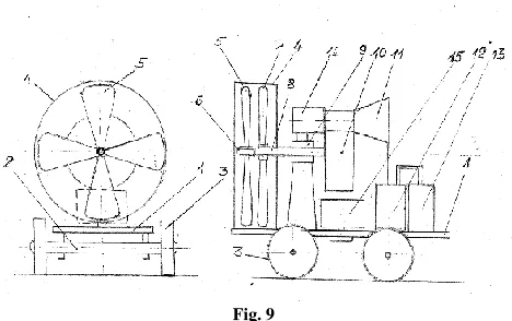
The design of the Venus rover is shown at Fig. 9
Fig. 9
The Venus rover is a carts made of titanium alloy. On the base of the carts 1, the axle 2 with wheels 3 is fastened. For creation of air flow the propeller has a nozzle 4 of cylindrical shape. The front air propeller 5 is installed on the inner shaft 6.The rear air propeller is installed on the outer shaft 8. The rotation of coaxial shafts 6 and 8 is carried out in the gas slider bearing 9.
In the project to control the movement of the Venus rover, a mechanical system , consisting of a gear wheeled reducer 10 , of the pneumatic compressor 11 and of the containers- accumulators of compressed air 12, 13, was developed.
[image:7.612.328.562.132.279.2]The developed scheme of mechanical transmission by means of reducer 10 is shown in Fig. 10.
International Journal of Emerging Technology and Advanced Engineering
Website: www.ijetae.com (ISSN 2250-2459, ISO 9001:2008 Certified Journal, Volume 7, Issue 5, May 2017)
184
The geared transmission provides the reverse rotation of the air propellers while maintaining their permanent mechanical connection, as well as provides power take off for own needs of mobile device.
The air propellers of the opposite rotation 3 and 4, which are fixed on the inner shaft 1 and outer shaft 2, transmit torque to the shaft 7 with the help of gears 5 and 6. On the shaft 7 a pneumatic compressor 11 is installed. The shaft 7 is connected with internal coaxial shaft 1 with the help of geared transmission ( via cogwheels 8.9 and 10). The intermediate gear 9 is necessary to ensure the opposite rotation of shafts 1 and 2. The gearbox shafts are installed into gas bearings 13. For the operation of the coaxial shaft, a special design of the gas bearing 12 was developed .The pneumatic compressor creates an in a closed pneumatic system the excess pressure of 15 MPa. It should be reminded, that the pneumatic systems of compressed air with gas energy accumulator are widespread in Earth conditions.
In the project this experience was used taking in account the peculiarities of operating conditions on Venus. At the Venus rover the compressed air is pumped into gas tanks 12 and 13 (Fig. 9). Through the piping, the compressed air is fed into all the bearing units of the mechanical transmission, which is shown in Fig.10.
In addition, the compressed air is used to control the carts while movement along the surface of Venus. At each wheel of the carts (Fig. 9) the brake pads with pneumatic drive are installed. When applying compressed air to the brake pad the force arisest which swings the carts. This allows to provide the movement the carts in any direction or to fully brake the carts in accordance with the intended program of the movement along the Venus surface. The control of the compressed air flow is accomplished using electromagnetic valve - a device, without which no bus or tram can operate.
The solenoid valve is an electrotechnical device, and first it is necessary to understand whether an electro technical device can operate in Venus conditions. When designing of the Venus rover, the calculations were conducted , which have showed the possibility of long-term operation of some electrotechnical devices, which the design is adapted to work on Venus.
As insulation materials it is possible to use asbestos and ceramic paddings, which can withstand temperatures of Venus. As material for conductors one can use electrotechnical copper, which electrical conductivity is reduced by half and accordingly one needs to increase the cross-section of the wires.
Due to the high temperature, the characteristics of magnetic conducting materials are also reduced. The cross-section of cores made of electrical steel must be respectively increased. Magnetic alloys of type Alnico or Diconel, which create a permanent magnetic field, retain on Venus their properties because their Curie point is above 450º.
As source of electrical energy for the Venus rover in this project, an electric generator with permanent magnets 14 (fig. 9) is used. Rotor of the generator 14 is installed on the shaft 7 (Fig. 10) , the shaft rotates continuously, because it is connected with the air propellers 1 and 2 and therefore, an EMF is constantly induced at the stator of the generator 14. When the electrical circuit is switched on, the monitor 15 (Fig. 9) begins to get the electrical current. In monitor 15, the detailed description of which is given below, the electrical control system of the Venus rover is located.
This system works under control of a computer, that receives commands from the control center, located on board of Venus plane.
The control system of the monitor has a regulator, which generates a current and sends it via a cable into compressed air system of the Venus rover,
In the system of compressed air, the electromagnetic valves are installed and when the current is turned on they feed the compressed air exactly into the pneumatic actuator , which should work at this point of time, providing control of the carts movement on the surface of Venus.
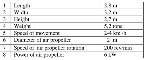
[image:8.612.319.572.529.634.2]The main characteristics of the Venus rover are given in Table 2
Table 2
The main characteristics of the Venus rover
1 Length 3,8 m 2 Width 3,2 m 3 Height 2,7 m 4 Weight 5,2 tons 5 Speed of movement 2-4 km /h 6 Diameter of air propeller 2 m 7 Speed of air propeller rotation 200 rev/min 8 Power of air propeller 6 kW
International Journal of Emerging Technology and Advanced Engineering
Website: www.ijetae.com (ISSN 2250-2459, ISO 9001:2008 Certified Journal, Volume 7, Issue 5, May 2017)
[image:9.612.65.270.141.269.2]185
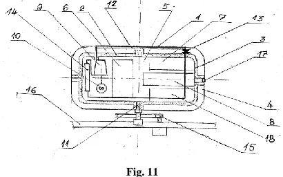
Fig. 11
In order to withstand the high atmospheric pressure on the surface of Venus, the monitor has a solid outer casing 1, made of titanium. To reduce a heat flow inside, the monitor is implemented as a Dewar vessel. It has an internal metal casings 4, which is covered on the outside with a layer of screen-vacuum insulation 3. By means of pumping out of air in the space between casings 4, the high vacuum is created.
The scientific measuring equipment 6, the control system 7 of the Venus rover 7, the TV system 8 for monitoring of Venus surface as well the communication system 18 with Venus plane and with orbital space laboratory, are placed in the inner space of the monitor- container, which is filled with gaseous helium under pressure of 1 bar.
Here the auxiliary equipment and a refrigerator unit are also located. The refrigerator unit works in accordance with Stirling thermal heat cycle and has the traditional diagram of cooling. As working substance in the refrigeration unit, the water vapor is used which has the boiling point of 470ºC at pressure of 45 atmospheres and the condensation temperature . of 50ºC at pressure of 1 atm. The refrigerator unit consists of compressor 9, which is operated by an electric motor 10. The motor 10 gets electric energy from the generator 14 (Fig. 10). Feeding of the current is carried out using the cable, which is entered inside the container through a sealed axial channel 11. The compressor compresses the water vapor adiabatically . The compressed steam enters into the refrigerator – condenser 12, where the delivering of heat into the atmosphere of Venus takes place.
The external cooling is ensured by the constant movement of gas inside the dense atmosphere of Venus, which removes the heat. When exiting the refrigerator, the working substance passes through the throttle valve 13,which lowers pressure. The temperature of the fluid is decreased.
The chilled working substance enters into the evaporator 14, where at constant pressure and temperature the evaporation takes place at the expense of heat of the cooled body. This process is accompanied by takeoff of the heat from the interior space of the container- monitor 5.
The value of the rated capacity of refrigerating unit - 500 W. The observation of the Venus surface is carried out using TV camera 8, which works with optical unit 17. The external part of the optical unit 17 is made of rock crystal, which can withstand high pressure and temperature. To ensure a full field of view, the container - monitor rotates relative to vertical axis with the help of pneumatic drive, which is fastened on the platform 16 of the Venus rover. The container-monitor has cylindrical shape
(cylinder diameter-1, 25 m, the height of the cylinder- 0.8 m). Weight of the container -300 kg.
It should b reminded that with the launch of the Venus rover the second stage of the expedition towards Venus comes to an end. Using the communication system, located in the cabin of the habitable capsule, astronauts carry out the checking of the readiness of the Venus rover to begin the movement along the Venus surface (in the meantime the Venus rover is in static state). Then the corresponding command is given and the control system 7
(Fig. 11) produces a signal that acts on the electromagnetic valve. The compressed air supply is switched on and the brake system of wheels of the Venus rover becomes unlocked. The Venus rover begins its movement along the Venus surface.
The orientation of the Venus rover on the surface is carried out using a computerized program of control system. The movements of the Venus rover are determined by topographical map of Venus, which was drawn up according to data of scanning , made by the station Magellan in 1994 year.
The route of the Venus rover was developed in accordance with the plans of studies, which are undertaken during many years in astronomical institutes and universities of different countries.
International Journal of Emerging Technology and Advanced Engineering
Website: www.ijetae.com (ISSN 2250-2459, ISO 9001:2008 Certified Journal, Volume 7, Issue 5, May 2017)
186
In the present project a designing was performed, in which the tank-container in addition to the main role plays a supporting role, becoming a laboratory-satellite, which orbits Venus.
V. ORBITAL SPACE LABORATORY
The orbital space laboratory is intended for monitoring processes in the atmosphere and on the surface of Venus. Using the space laboratory, television image of the Venus surface , which is received from transmitter of the Venus rover, is continuously transmitted to Earth.
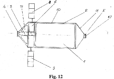
[image:10.612.72.268.333.470.2]Data of the atmosphere state of Venus are continuously coming from Venus plane in computers of the lab. The space laboratory moves around Venus at speed of 7.5 km/s at altitude of 90 km. The constructive scheme of the orbital laboratory is shown in Fig. 12.
Fig. 12
Tank-container 1 with liquid hydrogen 1 of 5 m diameter and of 15 m length has external casing 2 with screen-vacuum insulation. The feeding of liquid hydrogen in locomotive is done using axial cryogenic piping 3. The docking assembly, which connects the tank-container with the locomotive, has the tight seal of the cryogenic piping. On the opposite side a cryogenic bearing 5 is installed, as well as the docking assemble 12, which connects the space lab with habitable capsule during the main flight (see Fig. 3). Between the tank 1 with working substance and the docking assemble 4, the cylindrical container 6 is located with measuring instruments and container 7 with control equipment, as well the communication systems.
Energy supply to the orbital laboratory is provided using panels of semiconductor solar cells, which are put forward out from the external casing 10 of cylindrical form with end cone 11.
Launch of the orbital laboratory is carried out using the carrier rocket “Delta 4 Heavy».
The whole design of the orbital laboratory is assembled inside the fore part of the rocket.
After carrying out of the work package on putting into operation of the Venus plane, the Venus rover and orbital laboratory (which, according to the program of expedition, takes 7 day) astronauts begin to fulfill to the fourth stage of the expedition.
It should be reminded that the astronauts are inside the habitable capsules, which is connected with space locomotive (Fig. 3) and moves along the orbit around Venus at the speed of 7.5 km/s at height of 90 km.
As the habitable capsules, the device developed by the author , is used, which is already was used as a takeoff - landing capsule in flight towards Mars [1]. The capsule is equipped with chemical rocket engine and is able to carry out autonomous flight. To do this, the capsule detaches from the space train and using chemical rocket engine 6 (Fig. 3) commits maneuvering in the upper layers of the Venus atmosphere.
Study of the cloud layer, which begins from the height of 70 km and has thickness of 20 km, is held by a special program, using data obtained from Venus plane.
After completion of the program, the habitable capsule, using chemical rocket engine 6, is approaching to the space train (Fig. 3) and dock it with the help of docking assemble 5.
The fifth the last one, stage of the expedition begins . Astronauts are passing the last circuit in the Venus orbit, and turn on the electric rocket engines 2 of locomotive 1 (Fig. 3). The space train after reaching the second space speed enters into the calculated trajectory of flight from orbit of Venus towards orbit of Earth. The movement of the space train is shown in Fig. 4. At the beginning of the stay on the orbit of Venus the expedition was in point 2. During the work of the expedition, Venus has moved along orbit around Sun from point 2 into point 3. During the same time, Earth also has moved along its orbit around Sun from the point 2 ' into the point 3 ' . While carrying out the flight from the Venus orbit into the Earth orbit, space train should pass along the calculated trajectory from the point 3 into the point 4 '.
The change of the space train speed and the decrease of its weight during the flight can be seen in Fig. 5. After the train acceleration up to speed of 150 km/s, which happens in 9 days, the cruise electric rocket engines 2 (Fig. 3) are turned off.
International Journal of Emerging Technology and Advanced Engineering
Website: www.ijetae.com (ISSN 2250-2459, ISO 9001:2008 Certified Journal, Volume 7, Issue 5, May 2017)
187
The astronauts turn on the cruise electric rocket engines, which are turned around on 180 º. After braking during the 5 days the space train enters into circumterrestrial orbit. The return flight takes 16 days. After entering into circumterrestrial orbit, the space train is divided. The habitable capsule 4, using chemical rocket engine 6, taxis to and is docked to a moorage of the international space station. The astronauts pass inside the ISS . After medical examination, they are delivered to the Earth surface . This ends the expedition towards the planet Venus, which lasted 50 days.
Now let us try to assess the costs of the expedition. First of all, it should be taken in consideration, that as the locomotive for the space train, it can be used the locomotive, which constantly flies to Mars [1] and at the beginning of the expedition towards Venus is in the circumterrestrial orbit. And, secondly, the Martian takeoff-landing capsule, which is located at a moorage of the international space station, can be used as habitable capsule.
For the preliminary flight it is necessary to launch two tanks-containers 3 and 5, as well as the landing capsule 8, shown in Fig. 1.
The cost of three launches using the rocket "Delta 4 Heavy" will be 600 million dollars [5]. For the main flight it is necessary to launch the orbital space laboratory, shown in Fig. 12,using the carrier rocket “Delta 4 Heavy ". Thus, the total cost of the launches is 800 million dollars.
The main cost will be spent on the production of the Venus plain and the Venus rover. According to the preliminary estimations these expenses can be 1200 million dollars
Thus the total cost of the expedition towards Venus will be 2000 million dollars.
REFERENCES
[1] Rubinraut A. The Expedition to Mars. International Journal of Emerging Technology and Advanced Engineering. V5. Issue1. January 2015.
[2] Rubinraut A. Electric jet engine for flight to Mars. Patente DE102006022559 IFT CEATMS PsG.
[3] Rubinraut A. Raumschlepper für Fluge zu den Planeten des Sonnensystem DE 102011115997 A1 DPMA Espacenter
[4] А. Рой Движение по орбитам Мир. Москва. 1991 (in Russian)
[5] Feuerbacher D. Vom All in den Alltag 2007. Motobuch p.50