International Journal of Emerging Technology and Advanced Engineering
Website: www.ijetae.com (ISSN 2250-2459, UGC Approved List of Recommended Journal, Volume 8, Issue 3 March 2018)397
Overview of Interference Management in Ultra dense
Networks for future wireless
Swapna Tangelapalli
1,2, Dr.P.Pardha Saradhi
31
Research Scholar, Dept of ECE, K.L Deemed to be University,Vaddeshwaram, Andhra Pradesh.
2
Assistant Professor,Dept of ECE,Sreenidhi Institute of Science and Technology, Hyderabad, Telangana.
3Professor, dept of ECE, K.L Deemed to be University,Vaddeshwaram, Andhra Pradesh.
.
Abstract— The future mobile communications have number of intensive applications such as HD quality video, 3D visualization, and wearable devices, IOT, GHz speed and much more. The immense amount of traffic is generated due to linear increase in usage of smart devices, laptops and bandwidth hungry devices requires a paradigm shift in all aspects of mobile networks. Ultra Dense Network (UDN) is one of the leading ideas to meet this global demand. In UDNs, the number of access nodes called as enodes and the number of communication links required per unit area are densified. The current gain of network densification mainly comes from cell splitting, thereby serving more user equipments (UEs) simultaneously. This trend will decelerate as base station (BS) density gets closer to or even surpass UE density which forms an ultra-dense network (UDN). Thus, it is crucial to understand the behavior of ultra-densification for future network provisioning. Previous UDN studies focus on single BS association rule which results in a large portion of dormant BSs in the network. Thus, whether we can utilize these dormant BSs to improve system performance is an interesting question. In this paper, an introduction to ultra dense small cell networks with all parameters considerations and limitations are explained in detail.
Keywords—5G,UDN,MilimeterWave,CRAN,4GLTE.
I. INTRODUCTION
In 3rd generation cellular networks, the densification of macro-cell base stations (BSs) has improved the transmission rate in some areas. The deployment density of macro-cell Base Stations was about 4-5 BSs/km2. Then in 4th generation cellular networks, microcell Base Stations have been deployed satisfying the high speed transmission. In specified regions, the deployment density of microcell Base Stations is approximately 8-10 BSs/km2. In coming 5th generation cellular networks, the massive MIMO antennas will be integrated into BSs, where hundreds of antennas are utilized for transmitting data with GHz of frequency.. To satisfy the maximum coverage with minimum power transmission requirement, the density of 5G [2] BS should be very large up to 40-50 BS/km2.
Thus, the future 5th generation cellular network will be an ultra-dense cellular network. This paper is organized as introducing UDN scenario in chapter I followed with types of UDN networks in chapter II. The performance parameters and interference management scheme are discussed in chapter III and IV
respectively
.II. FUTURE WIRELESS COMMUNICATION
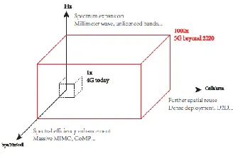
[image:1.612.319.483.387.497.2]The figure1 shows resource requirement in traffic demands of future wireless communications.
Figure 1.1Traffic demands in 5G.
Three major requirements to fulfill ever increasing network capacity are
1. Spectral Efficiency : Making use of advanced physical layer techniques such as modulation schemes ,multiplexing schemes, cooperative transmissions and massive MIMO
2. >6GHz frequency (Millimeter range)
3. Spatial Spectrum Reuse by network densifications.
Massive MIMO
International Journal of Emerging Technology and Advanced Engineering
Website: www.ijetae.com (ISSN 2250-2459, UGC Approved List of Recommended Journal, Volume 8, Issue 3 March 2018)398 MIMO is basically different from smart antenna techniques. MIMO generates directional beam form which enhances the performance of a single data signal. The different Wireless communication standards which includes WIFI (IEEE802.11n), HSPA+ , WIMAX , IEEE 802.11ac [8], and Long Term Evolution (4G LTE) contains MIMO as an essential element .To receive high data rates for multiple channels, spatial, time or frequency multiplexing are also used. Massive MIMO system consists of arrays of antenna containing hundreds of antennas .The proposed advantages of using Massive MIMO for 5th generation Wireless Systems [1] are:
Increase the capacity X 10 times ,
Improving the radiated energy-efficiency x100 times.
enables a significant reduction of latency <1ms
simplifies the MAC and Physical layer
Much more robust. Millimeter wave frequencies
Millimeter Wave uses the spectrum (30 GHz - 300 GHz) whereas the present consumer wireless systems operates at carrier frequencies <6 GHz. The use of shifting to Millimeter Wave carrier frequencies is the larger spectral channels, high throughput in small geographical areas, gigabit-per-second data rates, high bandwidth and much more. Millimeter Wave [17] communication also helps to provide high data rates and directed beam useful in many applications like wearable networks, vehicle to vehicle communication, autonomous robots,etc. Thus Millimeter Wave is receiving tremendous interest by academia, industry, and government for 5G cellular systems. The potential for MmWave is immense.
Millimeter-wave spectrum would allow the large bandwidth of spectrum beyond present channel bandwidth of 20MHZ in 4G. This increase in channel bandwidth helps to greatly increase the data capacity. Millimeter-wave frequencies, meets the demand of gigabits per second data rate, development of wireless communication in 60GHz unlicensed band is topic of great interest and research. The current RF spectrum 300MHz-3GHz is used in almost all commercial radio communications [4].
Network Densification
Densely deployed small cells are motivated by increasing the reuse of spectrum in the network area. It can decrease the number of user equipment (UE) at each BS, thereby reducing the competition for resources.
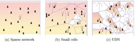
[image:2.612.321.540.272.342.2]There are several advantages of network densification. First, the cost of small cell deployment is much lower than the other two options. Both capital expenditure and operational expenditure of deploying small cells are considerably low compared to multi-antenna.Depending on the traffic demand, small cells can turn into sleep mode so that the energy consumption and interference can be reduced. According to Martin Cooper, the pioneer and visionary, the wireless capacity has doubled about every two years and increased around 1,000,000 fold from 1950 to 2000, also known as ‗Cooper‘s Law‘.
Figure 2. Evolution of ultra dense network
The 1 million gains are composed by 25x improvement from wider spectrum, 25 x improvements from advanced modulation and coding schemes, and an astonishing 1600x improvement brought by deploying more BSs and reducing cell size. By this taken, network densification has made significant contributions to capacity improvement in the past and is anticipated to play an important role in the future. Network densification has been recognized as the single most effective way to increase network capacity]. This is because the capacity scales linearly with the BS density as long as power-law path loss models (single-slope models) hold and every BS serves at least a single UE To this end, there is a growing amount of research on small cells. Ultra Dense Networks serves as another evolution from present heterogeneous networks.
The major difference between Ultra Dense Network and traditional LTE networks are as given below:
1) Many small cells are nearby present for a user. The network access nodes in Ultra Dense Networks environments are small cells with low transmission power and covering a small area (meters or tens of meters).
2) In ultra dense small cell networks many cells can be inactive. This helps to use the idle mode concept, i.e. the small cells can be turned off which helps to reduce the interference.
International Journal of Emerging Technology and Advanced Engineering
Website: www.ijetae.com (ISSN 2250-2459, UGC Approved List of Recommended Journal, Volume 8, Issue 3 March 2018)399 4) New frequency reuse techniques have to be developed .In traditional 4G cellular environment are code-division multiple access (CDMA) and orthogonal frequency-division multiple access (OFDMA) systems where the spectrum is reused in each cell.
5) The most challenging part of Ultra Dense Network is Backhauling which makes limitations on required high speed low delay network. The backhauling techniques to be used in small cell are the bottleneck of its capacity and limits air interface capacity [7]
6) In Ultra Dense Networks, the distance between Base stations and users is small enough to have a high probability of Line of Sight transmissions.
III. TYPES OF ULTRA DENSE ARCHITECTURE
Depending on the number of gateways in the macro-cell BS, there exist 2 types of network architectures:
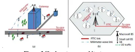
1. UDNs with Single Gateway:
[image:3.612.54.276.434.519.2]In this type of architecture, only one gateway is installed at the macro-cell BS. Along with it, large antennas (MIMO millimeter wave) are also erected to receive backhaul traffic from the microcell BSs. Whole of this backhaul traffic is the ready to be forwarded to the core network. This time the transmission occurs by Fiber to cell (FTTC) links [3][4].
Figure 3 Single gateway architecture 2. UDNs with Multiple Gateways:
[image:3.612.57.258.633.702.2]Apart from the multiple ones at macro-cell BS, multiple gateways are installed at several microcell BSs, which are judiciously chosen based on their relative geographies. Here, the traffic of small cells is transmitted to the multiple gateways in the macro-cell. All the backhaul traffic from the chosen microcell BSs and the macro-cell BS is collected and sent to the core network via FTTC links [3][4].
Figure 4 Multiple Gateways architecture
IV. PERFORMANCE METRIC FOR ULTRA DENSE NETWORK
The different performance metrics are basically related to SINR i.e. Signal to Interference plus Noise, coverage, average spectral efficiency, etc as explained below
1. signal to interference plus-noise ratio (SINR) 2. Data rate
3. Average spectral efficiency
The average number of transmitted bits per second per unit bandwidth is known as spectral efficiency.
Also helps to measure performance of single cell.
4. Area Spectral Efficiency
This factor increases by the reuse of spectrum per unit area.
It is an average achievable data rate per unit bandwidth per unit area.
5. Network Throughput
It is the the average number of successfully transmitted bits per sec. per Hz. per unit area.[7]
6. Energy Efficiency
It is defined as the ratio of the network throughput (or ASE) to power consumption per unit area.[7][9] 7. power consumption per unit area 8. Fairness
Evaluation of a given cell association, scheduling, or resource management scheme decides the fairness between different users.
V. PROBLEMS WITH ULTRA DENSE NETWORK
1.
Backhauling
2.
Cross tier and co-tier interference
3.
Frequency handover
4.
Placement and power control
5.
Interference Management
6.
Energy Efficiency
7.
Small Cell Discovery
8.
More spatial and temporal load fluctuation.
VI. INTERFERENCE MANAGEMENT IN ULTRA DENSE
NETWORK
International Journal of Emerging Technology and Advanced Engineering
Website: www.ijetae.com (ISSN 2250-2459, UGC Approved List of Recommended Journal, Volume 8, Issue 3 March 2018)400 Adaptive ON-OFF control methods are proposed and can be included in the interference management policy. Due to use of High frequencies ,short range transmission is dominant which results in much complicated nature of Ultra Dense Networks[2][3]
The three different categories of Interference Management are interference avoidance, interference cancellation, interference coordination or switching to Centralized Radio Access Network (CRAN)
In Ultra Dense Networks, the Interference Management functionalities should swiftly match with the characteristics of interference. Interference avoidance, Interference cancellation or Interference coordination should be selected and switched dynamically. The switching should be according to distribution and varying interference levels.
Interference Avoidance: In this technique the available resources are partitioned into orthogonal proportions in dimensions of time, frequency, space, power, code, etc. Orthogonal frequency division multiple access (OFDMA) is the most typical interference avoid-ance method adopted by 4G_LTE (Long Term Evolution) communications systems. Power controls methods can be applicable for both centralized and decentralized network architectures.
Interference Cancellation: In this the interference signals can be removed from aliasing signals in parallel or successive pattern before retrieval of original signal [6]. In the process of Interference cancellation, interference signals are rebuilt via channel estimation and demodulation/decoding. This process requires accurate channel estimation and large divergence of interference signal levels.
Interference Coordination: Using multi-antenna MIMO technology, the interference coordination is done by coordinating multiple transmitter antennas with associated multiple receiving antennas. For example, by make use of CoMP in downlink systems, enode base stations in the adjacent cells jointly design zero-forcing precoders to their interference channels.
The target is to force the desired signals received at the downlink to lie in the null space of their interference. In addition, IA is also a beamforming based interference coordination method [9], which aligns interference from multiple Txs into the same subspace at the receiver and leaves the intended signal subspace interference-free. In ultra dense networks, there must be good interaction between Interference Management and the network environment. Interference avoidance or cancellation or coordination should be selected and dynamically switched and varied according to the interference levels and distribution.
Interference Management entity for Ultra Dense Network using CRAN
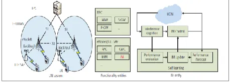
Interference Management can be combined with the centralized controller in the cloud radio access network (CRAN) architecture. Figure given below shows the the example of embedding the Interference management (IM) entity into LTE architecture [10].
In figure 4 LTE [4] system consist of the core network which include evolved packet core (EPC), and the evolved universal terrestrial radio access network (E-UTRAN) [3]. EPC contains Mobility management entity (MME), serving gateway (SGW) and packet data net-work gateway (PGW) whereas EUTRAN includes enodeB/LTE SAP which serves as the bridge between EPC and user equipments (UEs). EnodeBasestations (eNbs) and LTE SAPs are responsible for all radio-related functions, including radio admission control (RAC), connection mobility control (CMC), radio resource management (RRM), etc.
[image:4.612.318.548.616.699.2]In addition to the existing functional entities, In Ultra Dense Network scenario, eNodeB and LTE/SAP can be embedded with IM (Interference Management) module especially for handling interference in UDN. As shown in Figure 4, the Interference Management entity consists of three logical units. These are a) Interference cognition unit b) IM control unit and c) Self-learning unit.
International Journal of Emerging Technology and Advanced Engineering
Website: www.ijetae.com (ISSN 2250-2459, UGC Approved List of Recommended Journal, Volume 8, Issue 3 March 2018)401 The functions of these logical units are discussed below:
a. Interference Cognition Unit: It monitors the level of interference in the wireless environment using the feedback of UEs or the message exchange between eNodeBs/SAPs. For example, proactive which is high interference indicator and the reactive which is an overload indicator be exchanged over the X2 interface. It indicates potential high interference over specific resource blocks (RBs), and the average uplink interference plus noise levels respectively. The interference levels can also be estimated directly at User Equipment UE side. To sense the interference levels accurately and rapidly over the specified channels, enodeBase stations or SAPs could proactively send the ‗interference probe‘ requests to UEs through the physical downlink control channel, and accord-ingly, UEs will give the information of measured interference levels as a feedback physical uplink shared channel.
b. Interference Management Control Unit: This unit contains of an interference processing core along with the library comprising feasible interference management methods. The interference processing core is designed to analyze the real time interference information with historical knowledge of interference in the channel. Depending on this information, estimation of time or spatial interference distribution can be calculated. It provides the effective IM design. Afterward, an appropriate IM strategy can be selected from the Interference Management strategy library and the corresponding parameters can be optimized which would be based on the predefined target. Multiple Interference Management strategies also can be integrated and applied jointly for large number of enodeBasestations/SAP. For example, when multiantenna based strategies, such as CoMP and IA, are utilized, cooperative enodeBasestations/SAPs have to share channel state information (CSI), and the IM control units in enodeBasestation/SAPs must be capable of designing the IM parameters together. Considering correlated channel issues, make sure that channels of the transmission pairs in one cooperation cluster should not be correlated. c. Self Learning Unit: For have great impact of Interference Management on Ultra dense
Network, Self learning unit is designed. It facilitates interference Management control decisions along with Interference Management library updates. Specifically, once the IM strategy is adopted by the IM control unit, the performance of the IM strategy can be forecast. Then, according to the results of interference cognition, the performance of the currently applied IM strategy can be evaluated as well. Thus comparing the performance evaluation results with results of performance forecast, the self learning unit helps in updating the library and dynamically adjusts the Interference Management strategy parameters.
Interference Management using Adaptive ON OFF Power Control
In Ultra dense Networks, an adaptive ON OFF power control method can be applied. This can be implemented using proposed Interference Management entity. Considering a downlink LTE system, which uses OFDMA RBs by different SAPs which results only suffer of UES with inter cell interference? When each time slot begins, UEs should sense the interference levels on each BS and then feedback the information to the associated SAPs. Then the interference cognition unit in SAPs will collect the interference information.
VII. CONCLUSION
The future wireless network which has tremendous
International Journal of Emerging Technology and Advanced Engineering
Website: www.ijetae.com (ISSN 2250-2459, UGC Approved List of Recommended Journal, Volume 8, Issue 3 March 2018)402
References
[1] ―Ultra Dense Network: Challenges, Enabling Technologies and New Trends‖: Hao Peng, Yan Xiao, Yu-Ngok Ruyue, Yuan Yifei, ZTE Corporation Shenzhen, China, 2016.
[2] ―Ultra Dense Networks: The New Wireless Frontier for Enabling 5G Access‖: Antonis G. Gotsis, Stelios Stefanatos, and Angeliki Alexiou, 2015.
[3] Tangelapalli Swapna, Dr.P.Pardha saradhi, ―Survey with Analytical results on ultra dense 5G‖,Internatitonal journal of pure and Applied Mathematics, Volume 117,Issue 18,special Issue,2017,pages1-6.
[4] D. Sabella, P. Rost, Y. Sheng, E. Pateromichelakis, U. Salim, P. Guitton-Ouhamo, M. Di Girolamo, and G. Guiliani, ―RAN as a Service: Challenges of designing a flexible RAN architecture in a cloud-based heterogeneous mobile network,‖ 2013 Future Networks Summit, July 2013, Lisbon, Portugal.
[5] Tangelapalli Swapna, Dr.P.Pardha saradhi, ―An overview on Millimeter wave technology for future wireless Communications‖ ,International Journal of Research in Signal Processing, computing and communication system Design,Volume3, Issue 2,2017,ISSN:2395-3187
[6] L. Zhang, H.-C. Yang, and M. Hasna, ―Generalized area spectral efficiency: An effective performance metric for green wireless communications,‖ IEEE Trans. Commun., vol. 62, no. 2, pp. 747–757, Feb. 2014.
[7] C. Li, J. Zhang, and K. Letaief, ―Throughput and energy efficiency analysis of small cell networks with multi-antenna base stations,‖ IEEE Trans. Wireless Commun., vol. 13, no. 5, pp. 2505–2517, May 2014.
[8] A. Imran, A. Zoha, and A. Abu-Dayya, ―Challenges in 5G: How to Empower SON with Big Data for Enabling 5G,‖ IEEE Network, vol. 28, no. 6, Nov. 2014, pp. 27–33.
[9] E. Bjrnson, L. Sanguinetti, and M. Kountouris, ―Deploying dense networks for maximal energy efficiency: Small cells meet massive MIMO,‖ IEEE J. Sel. Areas Commun., vol. 34, no. 4, pp. 832–847, Apr. 2016.
[10] S. Stefania, I. Toufik, and M. Baker, LTE: The UMTS Long Term Evolution, John Wiley, 2015.
[11] J. Andrews, ―Seven ways that HetNets are a cellular paradigm shift,‖ IEEE Communications. Mag., vol. 51, no. 3, pp. 136–144, Mar. 2013.
[12] N. Bhushan, J. Li, D. Malladi, R. Gilmore, D. Brenner, A. Damnjanovic, R. T. Sukhavasi, C. Patel, and S. Geirhofer, ―Network densification: the dominant theme for wireless evolution into 5g,‖ IEEE communications Magazine, vol. 52, no. 2, February 2014.
[13] D. Lôpez-Pèrez, M. Ding, H. Claussen, and A. H. Jafari, ―Towards 1 gbps/ue in cellular systems: Understanding ultra-dense small cell deployments,‖ IEEE Communications Surveys Tutorials, vol. 17, no. 4, pp. 2078–2101, Fourthquarter 2015.
[14] E. G. Larsson, O. Edfors, F. Tufvesson, and T. L. Marzetta, ―Massive mimo for next generation wireless systems,‖
IEEECommunications Magazine, vol. 52 no. 2, pp. 186–195, February 2014.