International Journal of Emerging Technology and Advanced Engineering
Website: www.ijetae.com (ISSN 2250-2459,ISO 9001:2008 Certified Journal, Volume 4, Issue 5, May 2014)
709
An Anti-jam Adaptive Algorithm for GPS
Shi Yuhe
School of Science, Air Force Engineering University, Xi’an 710051, China Abstract—Traditional space-time adaptive processing
(STAP) algorithm not only have a big computation, but also cannot suppress the multiple narrowband jammer and the narrowband jammer which come from the same direction with the useful signal. Focus on these problems, an improved GPS anti-jam multistage nested Wiener filter (MSNWF) method which combines with multistage IIR lattice notch filter was proposed. The narrow-band jammer can be forecast and suppressed by using IIR lattice notch filter. The amount of computation can be reduced by using the improved MSNWF. The new method which can not only suppress both narrowband and broadband jammer effectively, but also improve the computation speed and SINR.
Keywords—GPS anti-jam, multistage nested Wiener filter, notch filter, space-time adaptive processing
I. INTRODUCTION
Space-time adaptive processing (STAP) technology was first proposed by Frost in 1972[1]. STAP techniques was emphasized by researchers in radar, navigation and other common areas for its high academic and applications value[2][3]. STAP technology began in the late 1990s[4]. STAP technology is applied to the GPS anti-jamming receiver was complete discussed firstly by Fante of Mitre company in 2000[5]. The full-dimensional STAP techniques have good anti-jamming performance, but the computation and storage is very large. As the performance of STAP algorithms are not sensitive to the dimensionality reduction process[6]. In order to better engineering applications, especially for fast changing signals, STAP technique requires the use of lower dimensional adaptive filtering method. The Multistage Nested Wiener filter is one of the main drop-dimensional adaptive filtering methods[7]. As the MSNWF avoid covariance matrix
inversion, eigenvalue decomposition, then the
computational complexity of MSNWF is reduced , and the real-time of space-time adaptive filtering is improved. The application of MSNWF to the GPS anti-jamming receiver is studied further by Myrick et al [8] [9][10].
If the jammer and the navigation signal reach the receiver in a different direction, the jammer can be effectively suppressed by STAP to GPS anti-jamming receiver, but Limited by the number of FIR filter taps, space-time adaptive processor frequency resolution is low, the frequency of the zero formed by a wide trap, then the loss of useful information is larger when the direction of jammer is same to the useful signal[11]. Aim to this problem, a novel method which combines multistage IIR notch filter with the power inversion algorithm based on improved MSNWF is proposed. The method can suppress the narrow-band and broadband jammer effectively, at the same time, the computation and storage of space-time adaptive processing algorithm can be reduced by using the MSNWF, then the processing speed can be increased.
II. THE STAP METHOD FOR GPSANTI-JAMMER RECEIVER
The number and form of jammer cannot be predicted by GPS receiver in advance, if there is no inertial navigation or inertial measurement units and other external auxiliary devices, it is difficult to determine the attitude of the antenna. The use of power inversion algorithm for space-time adaptive anti-jamming GPS receiver is the right choice[9]
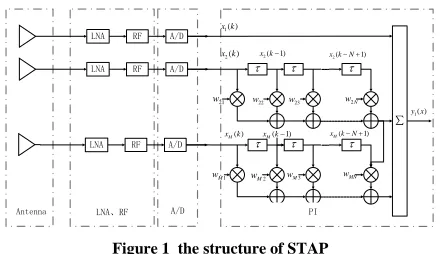
The figure 1 shows the structure of STAP based on power inverse algorithm. The space-time adaptive processor is consisted of M array elements, the 2~ M
channel are consisted of N order FIR filter,
21 22 2
[1, , ,..., ,..., ]T
N MN
is the weight. The powerinversion algorithm Minimize the total output
energy 2
out= { ( ) }
International Journal of Emerging Technology and Advanced Engineering
Website: www.ijetae.com (ISSN 2250-2459,ISO 9001:2008 Certified Journal, Volume 4, Issue 5, May 2014)
710
Therefore, the power inversion algorithm is equivalent to the maximum output SNR algorithm on navigation signal. Therefore, the power inversion algorithm is equivalent to the maximum output SNR algorithm.
LNA RF A/D
LNA RF A/D
LNA RF A/D
∑
1( )
x k
2( )
x k x k2(1) x k2( N1)
( 1)
M
x k N
( 1)
M x k
( )
M
x k
21
w w22 w23 w2N
MN w
1
M w
2
M w wM3
1( )
y x
[image:2.612.58.280.182.309.2]Antenna LNA、RF A/D PI
Figure 1 the structure of STAP
If not constrained, when
0,the Pout is the minimize,the result does not make sense, then the constrain is necessary.The constrain is WH s =constant, s is the desired signal vector, the value of s is sited to constant. Without loss of generality, constant is 1. then Optimization criteria is:
2
{ ( ) }
. . 1
out
H
P E y k
s t
s
(1)
From the formula 1, Power inversion algorithm is
essentially an adaptive algorithm with strict
constraints(
Hs1).If [1,0,0...0]T
s , the weigh vector
21 22 2
[1, , ,..., N,..., MN]T
.
Then2
Min( )
E y k{ ( ) }1 21 2 2 2
{ ( ) ( ) ... N ( 1) ...
E x k
x k
x k N
1 ( ) ... ( 1) }
M xM k MNxM k N
2 1
= { ( ) H ( )
Min M
E x k
X k1 1 2 M1 M M
H H
x x M x x M x x M
r
r
R
(2) Where
1 [ ( ) 1 ( )],
M
H
X X M
r E X k X k
1 1 [ 1( ) 1 ( )],
H X X
r E X k X k
[ ( ) ( )]
M M
H
x x M M
R E X k X k
2 2 2
( ) [ ( ), ( 1),..., ( 1),..., ( ),
M M
X k x k x k x k N x k
( 1),...
M
x k xM(k N 1)] ,T
Given
is the Min, the weight is Mopt . Zero thegradient ofM, then
1
2 2 0
M M M
M rX X RX X M
(3)
1
M M M
X X M X X
R
r (4)1
1
M M M
Mopt RX X rX X
(5)
Then , the optimal weight is:
1
1
[1, ] [1, ]
M M M
T T
opt Mopt RX X rX X
(6)
III. MULTISTAGE IIRNOTCH FILTER
In addition to nulling depth and width,the phase
characteristics of notch filter effect the relevant output SINR in the narrow-band interference suppression. This paper use a 2nd order IIR lattice notch filter. IIR lattice notch filter transfer function is:
1 2
1 2
( )( )
( )
( )( )
o o
p p
z z z z
H z
z z z z
(7)
While Zo2 , Zo2 are null point, Zp2 , Zp2 are pole,
1,2
o jw o
z e , 1,2 jwo p
z
e ,then the transfer function is:1 2
1 2
( )( ) 1+ 1 2
( )
2 1 (1+ )
( )(
o o
o o
jw jw
jw jw
z e z e z z
H z
z z
z e z e
(8)
The structure is:
( )
y n
( )
r t
1
z z1
1
1
1 / 2
Figure 2 2nd order IIR lattice notch filter
Where
decision notch frequency, so that wo is thenotch frequency
1
0 cos ( )
(9)Where
is the notch filter structure factor,
1.International Journal of Emerging Technology and Advanced Engineering
Website: www.ijetae.com (ISSN 2250-2459,ISO 9001:2008 Certified Journal, Volume 4, Issue 5, May 2014)
711
Among them, the frequency domain processing module consists of optimal windowing module, FFT transform module, interference detection module, spectral correction module and IIR notch coefficient generation module. Time domain processing part is IIR lattice notch modules [12].
A/D Optimum windowing FFT interference detection Spectrum correction IIR lattice notch filter generation of Notch coefficient ( )
[image:3.612.50.283.196.275.2]r t y n( )
Figure 3 The improved IIR notch
IV. THE IMPROVED GPSANTI-JAMMER STAP ALGORITHM
Literature [3] describes MSNWF algorithm to some
extent alleviated the space-time processing of
computational complexity, but the amount of computation is still too large. The following presents a forward recursion algorithm to MSNWF a new and improved process method that can further reduce the amount of calculation space-time processing. Compared with the traditional MSNWF dimension reduction method, it has a smaller amount of calculation, shorter response time [14].
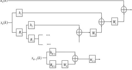
For a Gaussian process, the minimum mean square error and maximize the mutual information is equivalent. This idea can, through multi-level decomposition of a Wiener filter implementation. In particular the principle of the previous level, each level of this output is used as the input level into two subspaces. Pointing to a sub-space of the cross-correlation vector of the previous stage, and it is orthogonal to the other subspace. The cross-correlation vector is orthogonal to the same data is also a level of decomposition, the dimension of the data will subsequently reduced. The Wiener filter is shaped like pyramids, as shown in Figure 4, its role is similar filter banks. Specifically principle can be derived according to the literature [3].
0( )
d k
0( )
x k 1 h 1 B 2 h 2 B
...
...
2( )
H
x k
1
H
h
1
H
B WN
[image:3.612.53.281.576.697.2]1 N W 2 W 1 W
Figure 4 The structure of MSNWF
MSNWF forward recursion iterative process can be simplified through the deformation, the specific steps are as follows:...
Given t1h1,known |h1|| 1 。
Formula 1 1
1 1 1 1
i i
i i i i
x d
i H
x d x d
r h
r r
will be:
x
I,
y
I,
z
I
(10) SO
I
x x
x (11)Known
1 ( )1
B null h (12)
Substitute(12)into(11):
0 0 0
0 0 0
1 1 1 1 1 1 1 1 1
2 1 1
1 1 1 1 1 1 1 1
( ) ( ) ( )
|| || || || || ( ) ||
H H H
x x x
H H H
x x x
I t t R t I t t R t I t t R t
t k k
B R t B B R t I t t R t
(13) While 0 0
1 1 1 1 1 1 || || || || H x H x
B B R t k
B R t
(14)
Make
0
2 ( 1 1 ) 1
H x
f I t t R t (15)
Then 2 2 1 2 || || f t k f
(16)
Given
0
3 ( 1 1 2 2 ) 2
H H
x
f I t t t t R t (17)
Then
3 2 3/ || 3||
t k f f (18)
And so on, to p-level ,we have:
0
1
1 1 1
1
( )
p H
p x p
i
f I t t R t
(19)Where 1 || || p p p p f t k f
(20)
0 0 1 1 1 1 1 1 1 || || || || p H
i i x p
i i p
p
H
i x p
i p
B B R t
k
B R t
(21)International Journal of Emerging Technology and Advanced Engineering
Website: www.ijetae.com (ISSN 2250-2459,ISO 9001:2008 Certified Journal, Volume 4, Issue 5, May 2014)
712
Initialize t1h1 , g1I ,the forward iterative
algorithm is :
0
[image:4.612.65.273.276.608.2] [image:4.612.346.534.316.649.2]1 1 1 1 1 / || ||
Until || || 0
H
p p p p
p p x p
p p p p
p
g g t t
f g R t
t k f f
f
。
We can see the prior iterative algorithm of MSNWF and improved MSNWF in Table 1, Table 2.
TABLEI
ITERATIVE OF MSNWF AND IMPROVED MSNWF
MSNWF improved MSNWF
1 1
Initializet h,
1 ( )1
B null h ,
1
2,3 until 0
i N h
1 1 1
Initialize t h g, I
1
2,3 until 0
i N f
Iteration Iteration
2 2
1 1 1 1 1
1 /|| ||
i i
H H
i X i i X i
h B R h B R h
、
1 1 1
1 H
i i i i
g g t t
、
1
2、Binull h( ) 2、fig R ti x0i1
1 1
3
p
i j p
j
t B h
、
1 1 1 1
3、t ki*f/ ||f ||
TABLE II
COMPARISION OF MULTIPLICATIONS
Step MSNWF improved MSNWF
1
2 2
2(M1) P 2(M1)P 2 2
2
M P MP
2 2 2
(M1)P MP 2 2
(M1)P (M1)P
3 1 2
2
P MP
2
2MP
sum
2 2
3(M1)P+
2
3M2) +(P P1) / 2MP (
2 2
(1.5M -2M1)P
2
(1.5M1)P2MP
Table II shows both methods at the same level of decomposition is P, the main Step multiplication value to approximate estimates.
Table II shows the front iterative algorithm to reduce the amount of operation to bring, if M = 8, P = 5 The results of the computation of of MSNWF is 4385 algorithm, the computation of improved MSNWF is 2480.
The greater the value of M and P, the more significant reduction in computation. It show that the improved method can greatly reduce the amount of computation.
V. SIMULATION
A. The simulation comparation of 4 algorithms
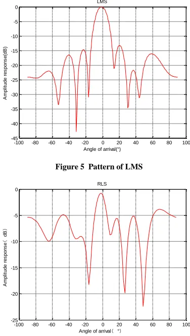
The following is the simulation comparation of LMS, RLS, SMI and improved MSNWF, based on the linear array, M = 8, P = 5, the working wavelength is 0.1m, array element spacing is 0.05m, the navigation signal C / A code the SNR is-20dB, interference and noise ratio are 30dB. Desired signal is 0 degree, the direction of the interference signal are -15 degrees, 25 degrees. Number of snapshots is 1000.
-100 -80 -60 -40 -20 0 20 40 60 80 100
-45 -40 -35 -30 -25 -20 -15 -10 -5 0
Angle of arrival(°)
A
m
p
lit
u
d
e
r
e
s
p
o
n
s
e
(d
B
)
LMS
Figure 5 Pattern of LMS
-100 -80 -60 -40 -20 0 20 40 60 80 100
-25 -20 -15 -10 -5 0
Angle of arrival(°)
A
m
p
lit
u
d
e
r
e
s
p
o
n
s
e
(
dB
)
RLS
International Journal of Emerging Technology and Advanced Engineering
Website: www.ijetae.com (ISSN 2250-2459,ISO 9001:2008 Certified Journal, Volume 4, Issue 5, May 2014)
713
-100 -80 -60 -40 -20 0 20 40 60 80 100
-45 -40 -35 -30 -25 -20 -15 -10 -5 0
SMI
Angle of arrival(°)
A
m
p
lit
u
d
e
r
e
s
p
o
n
s
e
(
dB
[image:5.612.77.255.137.467.2])
Figure 7 Pattern of SMI
-100 -80 -60 -40 -20 0 20 40 60 80 100
-80 -70 -60 -50 -40 -30 -20 -10 0
Angle of arrival(°)
A
m
p
lit
u
d
e
r
e
s
p
o
n
s
e
(
dB
)
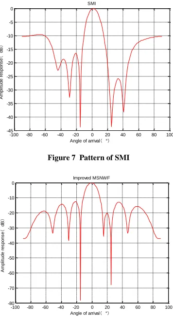
[image:5.612.358.526.316.461.2]Improved MSNWF
Figure 8 Pattern of improved MSNWF
We can see from the above simulation diagram :
1. All of the above algorithm can be formed for the direction of interference nulling , but LMS and RLS algorithm nulls in the direction of interference is less than -35dB, and non- interference with the direction of the LMS algorithm nulling actually deeper. SMI is better direction of interference nulling achieve -60dB, while the best results MSNWF reached nearly -90dB.
2. From the main lobe width, in addition to RLS reaches 40 ° , the remaining three algorithms are only 30 °, the board width is smaller, more concentrated signal direction , the impact of interference on its smaller , so the other three algorithms are compared good main lobe response .
3. Sidelines flap response point of view, I hope sidelobe peak as low as possible, is the energy is concentrated in the main lobe. LMS algorithm sidelobe peak to average close to -20dB for the best, but only just -5dB RLS algorithm worst , almost can not tell the main lobe side lobe , while the other two algorithms centered SMI average -15dB, MSNWF average -17dB.
4. From the stability of the algorithm is , after several simulation , LMS and RLS algorithm is very unstable , each iteration of the simulation out quite different , but the basic stability of SMI and MSNWF algorithms , especially MSNWF simulation diagram unchanged.
B. Comparison of algorithms in Different number of snapshots
To further study the number of snapshots that sampling points on the impact of anti-jamming algorithm we were on the LMS, RLS, SMI and proposed improvements MSNWF simulation comparison.
Figure 9 to 12 are LMS, RLS, SMI MSNWF with improved algorithm proposed in the snapshot number of beamforming 500, 1000 pattern.
-100 -80 -60 -40 -20 0 20 40 60 80 100
-60 -50 -40 -30 -20 -10 0
Angle of arrival(°)
A
m
p
li
tu
d
e
r
e
s
p
o
n
s
e
(d
B
)
LMS
snapshots=500 snapshots=1000 snapshots=2000
Figure 9 LMS in Different number of snapshots
-100 -80 -60 -40 -20 0 20 40 60 80 100
-30 -25 -20 -15 -10 -5 0
Angle of arrival(°)
A
m
p
li
tu
d
e
r
e
s
p
o
n
s
e
(
dB
)
RLS
snapshots=500 snapshots=1000 snapshots=2000
[image:5.612.351.530.481.655.2]International Journal of Emerging Technology and Advanced Engineering
Website: www.ijetae.com (ISSN 2250-2459,ISO 9001:2008 Certified Journal, Volume 4, Issue 5, May 2014)
714
-100 -80 -60 -40 -20 0 20 40 60 80 100
-60 -50 -40 -30 -20 -10 0
SMI
Angle of arrival(°)
A
m
p
lit
u
d
e
r
e
s
p
o
n
s
e
(
dB
)
snapshots=500
[image:6.612.77.254.141.282.2]snapshots=1000 snapshots=2000
Figure 11 SMI in Different number of snapshots
-100 -80 -60 -40 -20 0 20 40 60 80 100
-100 -90 -80 -70 -60 -50 -40 -30 -20 -10 0
Angle of arrival(°)
A
m
p
lit
u
d
e
r
e
s
p
o
n
s
e
(
dB
)
Improved MSNWF
snapshots=500 snapshots=1000 snapshots=2000
Figure 12 Improved MSNWF in Different number of snapshots
From the above chart comparison shows :
1. Overall, as the number of snapshots increases, more and more narrow main lobe , nulls deeper , more low sidelobe peak . Interference effect is getting better and better .
2. Snapshots LMS algorithm for greater impact , increasing the number of snapshots in time , LMS algorithm simulation diagram nulling deepened and more accurate orientation angle is also much lower sidelobe peak , anti-interference performance greatly improved.
3. Snapshots on RLS algorithm changes improved though seen from the figure , significant changes in the number , but not anti-jamming performance , the reason may be due to poor stability of the RLS algorithm .
4. Snapshots and maximizes performance for SMI also the most obvious improvement is the main lobe width is greatly reduced. At the same time there are certain side-lobe peak amplitude decreases, performance improved significantly .
5. Snapshots algorithm for improved MSNWF impact is not very obvious , but there is a small peak sidelobe reduction in Chengdu . It can be seen that the improved algorithm MSNWF more stable than the other three algorithms . This point can be seen after the MSNWF improved superiority of the algorithm . Especially in the case of a small number of snapshots , improved MSNWF has very good anti-jamming performance
C. Comparison of algorithms of time
In order to study the computing speed of the four algorithms, simulation parameters are the same parameters
and 4.1, the results shown in Table III.
TABLE III
4ALGORITHMS IN TIME
algorithm
The time required computing 100
times(S)
LMS 2.383760
RLS 0.276516
SMI 0.046518
MSNWF 0.117221
Improved MSNWF 0.063478
D. Comparation of traditional STAP and improved STAP when there is interference in the desired direction
[image:6.612.329.549.295.455.2]International Journal of Emerging Technology and Advanced Engineering
Website: www.ijetae.com (ISSN 2250-2459,ISO 9001:2008 Certified Journal, Volume 4, Issue 5, May 2014)
715
100 150 200 250 300 350 400 450 500
-33 -32 -31 -30 -29 -28 -27
Snapshots
S
IN
R
(d
B
)
[image:7.612.350.531.142.302.2]STAP Improved STAP
Figure 13 The comparation of traditional STAP and improved STAP
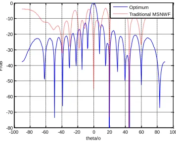
Shown in Figure 14, the traditional STAP algorithm 20 ° and 45 ° of broadband interference suppression effect is very good, but when the narrowband interference and the desired signal from the same direction, in the direction (0 °) produces nulls, so desired signal is also generated a great suppression.
Shown in Figure 15, the improved algorithm STAP only for 20 ° and 45 ° with good broadband interference suppression effect of interference, and does not produce the desired signal of 0 ° suppressed, because the same direction ahead of narrowband interference has been trapped wave filter prediction and filtering
-100 -80 -60 -40 -20 0 20 40 60 80 100
-80 -70 -60 -50 -40 -30 -20 -10 0
theta/o
F/
d
B
[image:7.612.77.259.143.263.2]Optimum Traditional MSNWF
Figure 14 The traditional MSNWF
-100 -80 -60 -40 -20 0 20 40 60 80 100
-80 -70 -60 -50 -40 -30 -20 -10 0
theta/o
F/
d
B
Optimum Improved MSNWF
Figure 15 The improved MSNWF
In summary, this paper proposes an improved STAP algorithm can effectively filter out the desired signal in phase with the NBI, a stable broadband anti-jamming performance, but also greatly reduces the amount of computation dimension reduction process.
VI. CONCLUSION
In this paper, the traditional STAP algorithm is computationally intensive and cannot filter out the desired signal in phase with the interference signal problem, propose a new time-frequency domain binding cascade IIR lattice notch filter and improving the power inversion algorithm MSNWF method spectrum correction technique
used to accurately estimate the frequency of the
[image:7.612.77.255.433.576.2]International Journal of Emerging Technology and Advanced Engineering
Website: www.ijetae.com (ISSN 2250-2459,ISO 9001:2008 Certified Journal, Volume 4, Issue 5, May 2014)
716
REFERENCES
[1] O. L. Frost. An algorithm for linearly constrained adaptive array processing[J]. Proceedings of the IEEE. 1972, 60(8): 926-935. [2] Y. L. Wang, Y. N. Peng. Space-time Adaptive Signal Processing
[M]. Beijing: TSINGHUA UNIVERSITY PRESS, 2000.
[3] W. F. Gong, X. Sun, S. L. Wu. Research on Adaptive Reduced Dimension STAP Anti-Interference Based on Multistage Nested Wiener Filter[J]. Journal of Astronautics, 2010, 31(10): 2360:2366. [4] G. F. Hatke. Adaptive array processing for wideband nulling in GPS
systems[C]. Thirty-Second Asilomar Conference on Signals, Systems & Computers, 1998, 2: 1332-1336.
[5] R. L. Fante, J. J. Vaccaro. Wideband cancellation of interference in a GPS receive array[J]. IEEE Transactions on Aerospace and Electronic Systems. 2000, 36(2): 549-564.
[6] M. L. Honig, J. S. Goldstein. Adaptive reduced-rank interference suppression based on the multistage Wiener filter[J]. IEEE Transactions on Communications. 2002, 50(6): 986-994.
[7] Q. J. Ding, Y. L. Wang, Y. S. Zhang. Efficient Algorithms for Implementing Multistage Wiener Filter in Adaptive Arrays[J].Journal of Electronics & Information Technology, 2006, 28(5): 936:940(in Chinese)
[8] W. L. Myrick, M. D. Zoltowski, J. S. Goldstein. GPS jammer suppression with low-sample support using reduced-rank power minimization[C]. Tenth IEEE Workshop on Statistical Signal and Array Processing, 2000: 514-518.
[9] W. F. Gong, X .Sun, S. L. Wu. Robust GPS interference suppression method in the case of small sample size[J] . Journal on Communications, 2010, 31(8A):143:147
[10] X. C. Sun, F. K. Huang, Q. Chen, et al. Joint space-time adaptive filtering for GPS anti-jamming receiver[J]. Journal of China Institute of Communications, 2004, 25(8): 168: 173
[11] C. Ren, Y. Q .Wang. An Improved Anti-jamming Algorithm Based on Space-time Adaptive Processing[J]. ACTA ARMAMENTARH, 2010, 31(12): 1622- 1626.