5036
BIO-INSPIRED A NOVEL CONTINUUM ROBOT ARM WITH
VARIABLE BACKBONE DESIGN: MODELLING AND
VALIDATION
1AZAMAT YESHMUKHAMETOV, 2ZHOLDAS BURIBAYEV, 3YEDILKHAN AMIRGALIYEV, 4BEIBUT AMIRGALIYEV, 3KONSTANTIN LATUTA
1Tokai University, Graduate School of Science and Technology, Japan
1Satbayev University, Kazakhstan
2Al-Farabi Kazakh National University, Kazakhstan
2,3Institute of Information and Computational TechnologiesCS MES RK, Kazakhstan,
3Suleyman Demirel University,Kazakhstan
4International Information Technology University, Kazakhstan
E-mail: 1[email protected], 2[email protected], 3[email protected],
ABSTRACT
Dramatic growth in the robotics industry demands robots with exceptional working capabilities such as working in a confined environment and with safety features. Likewise, high requirement needs to meet robots of the new generation. In such a case, bio-inspired continuum robots could be a good alternative solution for such needs. This research paper proposes a continuum robot arm inspired by an elephant trunk. The novelty of this research is proposed variable backbone hardness provided by coil compression springs, such as elephant trunk muscles. Thus, the proposed robot design allows working in a highly constrained environment, such as the agriculture sector or in the rescue operations, where the working environment is unstructured and severe which requires exceptional features from the robot. This research paper will cover the following topics; backbone design concept, geometry modelling, forward kinematic solution and the robot application as well.
Keywords: Bio-Inspired Manipulator, Continuum Robot, Elephant Trunk, Kinematics, Design.
1. INTRODUCTION
According to the continuum robot backbone, it divides into three main types: discrete continuum robot, hard continuum robot, and a soft continuum robot arm. Discrete continuum robot arm backbone consists of universal joints and mostly actuates by cable. Moreover, discrete continuum robot arm relatively heavier and could produce more torque rather than other types of continuum robots. In other words, discrete continuum arm looks like a multi-joint robot arm or gripper [1,25]. Secondly, hard continuum robots represent robot with shape memory alloy and springs backbone and connected by spacer discs which are made of plastic or metal. Soft continuum robot arm backbone is made of rubber or silicone. Hard continuum robots and soft continuum robots features are similar, for instance, in their application those robots designed mostly for
inspection purpose, for example in minimally invasive surgery [2]. One of the main difference of those backbone type with a discrete continuum robot arm is torque and payload capacity property. Relatively, discrete continuum robots provide higher payload capacity rather than other continuum manipulators [3] In this research we consider hard continuum robot, but with variable backbone hardness .which is changed the traditional view on backbone properties.
5037 However, pneumo actuators demand more space and maintenance. The less popular actuation system is provided by the dielectric elastomer [6]. Dielectric elastomer is polymer material which can change the shape by applying voltage, unfortunately, it requires high voltage and mechanical property of the material will decrease after numerous application. However, the exceptional property of the material is lightness. In the proposed robot, we utilize a wire driven system of actuation.
In the field of robotics, continuum robots became more popular because of their exceptional properties such as dexterity and flexibility, which is inherited from hyper-redundant design and soft materials [7,8]. However, controlling of continuum manipulator is a seriously challenging issue because of the flexibility of the shape and structure it demands constant cable or body tension.
Numerous researches had been conducted on continuum robots from the late of 1960s Anderson and Horn made a first continuum robot arm called Tensor Arm for underwater manipulation (Table 1). Moreover, a great contribution to the development of continuum robots had been done by professor Hirose from Tokyo Institute of Technology, Prof. Hirose proposed kinematic modelling based on pure bending and geometric formulation.
Furthermore, novel kinematics for any type of continuum robots had been proposed by Jones and Walker, proposed kinematics was adapted via DH convention for continuum robots [18,19,20,21]. One of the main features of this solution is a shape control [15,16]. In the early 2000’s UK company OC robotics presented new continuum arm with tremendous payload capacity and accurate [8]. Similar research had been conducted by Hanna and Walker presented a continuum robot named Elephant Trunk which is able to perform a linear motion and with solved inverse kinematics [10]. Moreover, Han Yuan and Zheng li also proposed a kinematic analysis of the continuum robot based on a static model [5]. Furthermore, Dong. et. all from Nottingham University proposed continuum robot arm design with twin-pivot compliant joint, which actuated by a cable, and Dong proposed kinematics based on cable length variation [7].
Moreover, in continuum robot dynamic problem is also a challenging issue, soft backbone and less rigid structure bring more difficulties in statics and dynamics. Therefore, the majority of
continuum robots work upside down to neglect gravitation or for inspection scientists miniaturize the size of continuum robot. For example, Suzumori and his team designed a flexible microactuator powered by compressed air [9,11,12], and Dupont and his team developed a mesosize continuum manipulator for minimally invasive surgery [13,14].
[image:2.612.313.526.321.699.2]This paper is an extended work of conference proceeding ICMMR 2018 [26] . will explain the continuum robot construction design with variable helical compressional springs. Moreover, the robot design concept, kinematic formulation and kinematics of a single section would be discussed.
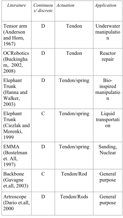
Table 1: History and classification of the continuum robot arm.
Literature Continuou s/ discrete
Actuation Application
Tensor arm (Anderson and Horn, 1967)
D Tendon Underwater manipulatio
n
OCRobotics (Buckingha m, 2002, 2008)
D Tendon Reactor repair
Elephant Trunk (Hanna and Walker, 2003)
D Tendon/spring Bio-inspired manipulatio
n
Elephant Trunk (Ciezlak and Morenki, 1999
C Tendon/spring Liquid transportati
on
EMMA (Bostelman et. All, 1997)
D Tendon/spring Sanding, Nuclear
Backbone (Gavagne et.all, 2003)
C Tendon/Rod General purpose
Artroscope (Dario et.all, 2000
5038
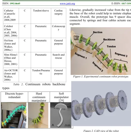
Catheter (Camarilo et.all, 2008,2009
C Tendon/sleeve Cardiac surgery
Colobot (Chen et.all, 2004, 2005, 2006)
C Pneumatic Colonoscop y
OctArm (Jones and Walker, 2006a )
C Pneumatic General purpose
Slim Slime1 (Ohno and Hirose, 2000, 2001)
C Pneumatic Search and rescue
Air-OCTOR (Jones and Walker, 2006)
C Tendon/Pneuma tic
General purpose
Table 2. Continuum robots backbone types
Discrete
hyper-redundant continuum Hard manipulator
Soft manipulator
[29]
2. DESIGN CONCEPT
This research paper presents continuum robot arm inspired from elephant trunk, and with multi-segment actuating system. The structure of the robot is similar to the traditional snake-like manipulator, slender arm, serially connected hard spacers discs via helical springs. The robot actuated via 1 mm steel wire connected to the stepping motor pulley.
One of the main specified features of the robot is designed backbone structure. For this prototype, we utilized 3 types of helical compressional springs with variable constant values. For instance, for a first segment we used compression spring WL20-30 with spring constant 35.3H/mm, for middle segment WF20-30 with constant value 13.2H/mm, and for tip segment WR20-30 with the lowest value 8.8H/mm.
Likewise, gradually increased value from the tip to the base of the robot could help to imitate elephant muscle. Overall, the prototype has 9 spacer discs connected by springs and four cables actuate each segment.
[image:3.612.82.517.67.504.2]
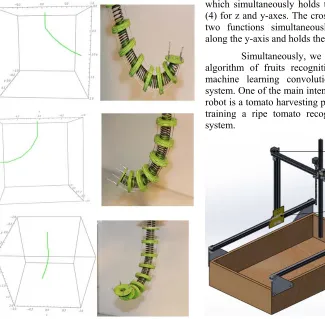
Figure 1. Experimental continuum robot prototype.
Figure 2. CAD view of the robot
The reason for using variable spring constant comes from a concern about static and natural formation. For this idea, an optimal choice drawn came after several experiments in the laboratory.
So, the main conclusion is the backbone hardness should be gradually decreased, from, bottom to the top section of the robot. Such kind of variation will increase stability and dexterity of the robot as well [figure4].
5039 pretension device to compensate cable tension and provide a constant hardness to the slender part of the continuum manipulators [27,28].
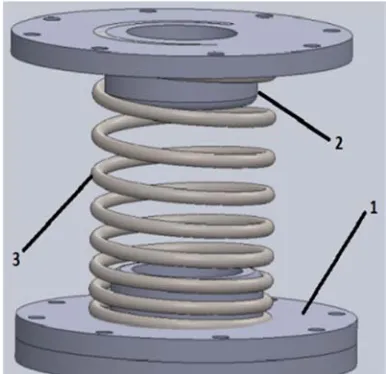
Figure 3. A single section of the robot: 1-spacer disc, 2-constraint for spring, 3- helical compression spring.
[image:4.612.317.531.47.278.2]The distance between spacer discs could be determined by the length of compressional springs and it should not exceed over 40 mm. Because of the long-distance of the segment evoke to the friction and interference between cables and robot parts. Moreover, inner interference increases friction inside of the structure. Thus, the desired distance is between 30-40 mm per segment. Likewise, design with an extensional feature makes solves one issue related to wire tension. During the work manipulators, the slender part requires an extensional length of the wire and at the same time opposite motor should pull wire, so in such case, the slender part of the robot can handle this problem mechanically. So, this is one of the main beneficial features of the robot design.
[image:4.612.97.290.128.315.2]Figure 4. Comparison of continuum robot backbone hardness
Figure 3 illustrates the main difference of the backbone hardness, so in the construction of the robot, this fact had been taking into an account. Therefore, in prototype, there are 3 sections[fig1], so in section-1 mounted the hardest spring WL20-30, in section-2 WF20-WL20-30, in section-3 softest spring WR20-30, these customized springs had been ordered from company MISUMI. The reason for using springs for the backbone is elongation and shrinking feature. Which gives one more additional degree of freedom. However, using of flexible backbone will accuse buckling of the flexible backbone of the force along the backbone exceeds the bucking load [7]. Therefore, the better solution in such case is to design the backbone which can mechanically minimize the twisting angle.
5040 the conducted experiments, the same backbone hardness could increase the required motor torque for joint bending.
[image:5.612.91.305.292.473.2]Figure 5. Force relation to the section radius.
Figure 6. Relation of serially connected number of springs and hardness.
KINEMATICS OF TENDON-DRIVEN CONTINUUM ROBOT
3.1. STRUCTURE
The Flexible backbone continuum robot structure proposed in this paper consists of three modules. Each module contains three sections of individual helical compression springs connected with a 3d printed compliant joints. Each module is divided into three segments and consists of springs with different spring stiffness. The pictorial description for the nomenclature of the structure is given below in Fig. 1 and Fig. 3.
The kinematic model of each module of the continuum robot is based on four assumptions reported as follows
Assumption 1: The centre curve of the helical compression spring is constant.
Assumption 2: The piece-wise curvature of the helical compression spring is constant.
Assumption 3: No friction force is acting on the vertical spring-mass system.
Assumption 4: It is assumed that the centerline keeps a constant value because of symmetry of the spring module.
Continuum manipulators kinematics nowadays could be solved with two different approaches; firstly, we can calculate kinematics by using a shape angles and radiuses, this approach is pretty popular and applied in such manipulators where manipulator shape plays the main role. Secondly, by using homogenous transformation matrices which is the pretty similar method of DH convention, such a way provides an easier solution and could be applied mostly for discrete continuum manipulators.
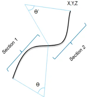
Figure 7. shape control method
[image:5.612.356.503.345.509.2] [image:5.612.356.528.580.685.2]5041 In this research, the robot actuates a single wire with a single motor with drum-type pulleys, which make to neglect a problem with wire tension. In addition, the robot working arrangement is a vertical, where we could neglect a gravity as well. 3.2 Forward Kinematic Model for a Single Module
The purpose of the forward kinematics on the continuum robot is an analysis to determine tip position with given cable length. As mentioned above the joints of the robot is compliant, so is assumed to perform pure arc shape in case of bending.
For this prototype, we used kinematic formulation developed by Jones and Walker, which is the modified formulation of DH convention for continuum robots. In this new proposed design, the kinematic error related to the twisting problem is minimized thus the system provides us with a more accurate original configuration. The model is first presented with all the assumptions mentioned in this paper to compute the kinematics of the continuum robot and the follow-up experiments indicate that these assumptions are reasonable. The required cable lengths at default configuration of the continuum robot are calculated and compared with the real lengths, which is a constant value with cables fully tensioned to prove that cables can maintain the tension well based this design proposed.
End-effector and orientation of the single section are derived by via DH method, after obtaining DH parameters (β1 and β2) with given cable length (l1 l2,l3, and l4), in this case, l1 and l3 are cable pairs and l2 and l4 pairs too. Based on cable length, we need to find bending angles. Due to the length of the pair of cables in one gap is constant to 2ljoint.
(1)
where is given
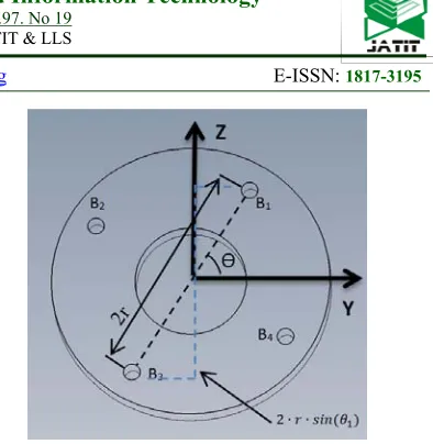
As shown in Fig 9. The projection of line B1B3 on joint 1 bending plane can be calculated as:
(2)
where r and θ1 are given.
Hence, from joint1 bending section view, the following equation can be given by:
(3)
Similarly, the difference between and
can be calculated.
(4)
Likewise, from joint 2 bending section view, another two equations can be obtained.
(5)
and
(6)
Then in order to eliminate parameters
and , adding the left and right side of Eq.(3) with the left and right sides of Eq.(5), respectively
(7)
where is given.
Similarly, the other equation can be obtained.
(8)
where is given.
Based on equations (7) and (8), the bending angles β1 and β2 can be written in terms of
cable length l1 and l3, θ1, r and the joint length ljoint as: ' l ' l joint l = ' l '
l3 1 2 1 1
joint l
1sin 2 2
1B = r θ
B m 2 1 sin 1 sin 2 2 2 1 sin 2 1 1 1
2ljoint 'l 'l=mBB β = r θ β
' l2 ' l4 2 1 sin 1 2 sin 2 2 2 2
2ljoint 'l 'l = r π θ β
2 2 sin 1 cos 2 2 1 12ljoint l'' l''= r θ β
2 2 sin 1 2 cos 2 2 1 1
2ljoint l'' l''= r π θ β
' l1 '' l1
2 2 sin 1 cos 2 2 1 sin 1 sin 2 12 ljoint l= r θ β + r θ β
1 l
2 2 sin 1 sin 2 2 1 sin 1 cos 2 22ljoint l = r θ β + r θ β
5042 (9)
[image:7.612.328.525.44.246.2]Then, by using all these parameters DH table would be obtained (Table1).
Figure 10. Projection of the structure.
Figure 11. Joint bending section. Disc B top view.
At first, the kinematics for a single section of a module was analyzed and then further the forward kinematic analysis for that complete module was derived. Since all the segments in one module has the same configuration and arranged parallel to each other it was simple to apply the analysis a single segment to other remaining segments of a module. In other modules since the spring stiffness is different from the previous modules, the spring stiffness constant value varies with different modules in the derived model. Table2. D-H parameters for a single segment
D-H Table
Link Ɵ a d
α
1 0 0
0
2 β1 0
𝜋
2
3 β2 0
𝜋
2
The purpose of forward kinematics analysis is to determine the position and orientation of the end-effector or the tip of the continuum robot given the lengths of the cables and motor-pulley specifications. The tip position and orientation for a single section of the continuum robot was derived using the Denavit-Hartenberg (DH) method. First, the DH parameters were obtained, which are basically the cable lengths l1 and l2 and the bending
angles β1 and β2.Later based on the transformation
matrix for each link, the tip position and orientation of a segment was calculated.
[image:7.612.90.306.72.190.2]5043 (10)
(11)
Then the position and orientation of the single segment could be calculated as:
(13)
In the case of calculation all segments of one section would be in a similar way, as expressed below:
(14)
So, the whole robot segments or the robot’s final end-effector would be calculated as :
(15)
Here and are segments of
the robot.
4. EXPERIMENTAL VALIDATION
For the experiment of the proposed prototype, Arduino Uno had been used as a controller and servo shield to control eight DC servo motors. Servo shield can provide extra current to the motors in case of loading, on this experiment servo motors work on 6 voltage and 0.5A. Technically, during the motion servo motors consumed more current than the rated current on their datasheet. So, in control, 8 motors we divided into 3 groups: 2 motors for the base section, 2 motors for the middle section and 4 motors for the tip section. The main limitation of the conducted experiment is a servo motor rotational limitations, standard servo motors can rotate only 180 degrees, which constrains the robot bending motions. Actuation of the wires are pulleys which are directly connected to the servo motors, so in case of increasing of the pulley diameter, motor required more torque, so in this experiment, we tested various pulley diameters to figure out proper diameter for servo motor with the rated torque 0.12N•m. 1 0 0 0 1 0 0 0 1 0 0 0 2 1 tan 1 0 0 1 0 β β joint l = T
1 0 0 0 1 0 1 sin 2 2 tan 2 2 1 tan 1 1 cos 1 0 0 1 sin 1 cos 2 2 tan 2 2 1 tan 1 1 sin 0 1 cos 1 β β β joint l + disk l + β β joint l β β β β β joint l + disk l + β β joint l β β = T 1 0 0 0 1 0 1 sin 2 2 tan 2 1 cos 1 0 0 1 sin 1 cos 2 2 tan 2 1 sin 0 1 cos 2 β β β joint l + disk l β β β β β joint l + disk l β β = T 2 T 1 T 0 T = 2 0 T 2 T 1 T 0 T = 2 0 (T = n segment T III T II T I T = robot T II T , I5044 Figure 12. Robot motor arrangement.
For the simulation of the robot kinematics Matematica software had been used. Simulation and actual experiment had been done separately, because of Matematica cannot handle the speed of calculation to control a robot in real-time. Fig 13, demonstrates of correlation of simulation and experimental robot kinematics.
Figure 13. Simulation results
5. INTENDED APPLICATION
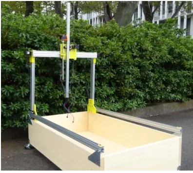
Proposed flexible manipulator would be utilized as a harvesting tool in CNC based farming robot machine prototype named FaRo.(see fig. 14).
The design of the proposed agriculture robot based on a CNC machine platform. Likewise, robot design makes the environment structured and predictable for the robot, rather than planting in a greenhouse or on the field. Therefore, it has three degrees of freedom, which is well enough for watering, weeding and seeding processes. On Z-axis tip mounted special universal tool mount system for changing tools for watering, weeding, seeding and measuring soil moisture.
As shown in Figure 3, the farming robot has 4 stepper motors (5), two for the x-axis and single motors for y and z-axes. The base platform of the robot is made from wood (1). The overhead robot frame is constructed with aluminium beams which are supported by corner brackets (2). The gantry (3) serves as the translation along the x-axis which simultaneously holds the aluminium profile (4) for z and y-axes. The cross gantry (6) performs two functions simultaneously: translates motion along the y-axis and holds the z-axis.
Simultaneously, we are developing a new algorithm of fruits recognition system based on machine learning convolutional neural network system. One of the main intended application of the robot is a tomato harvesting process, so now we are training a ripe tomato recognition and detection system.
[image:9.612.108.433.343.662.2]5045 Figure 15. The intended application
The harvesting process is a very work heavy and time- consuming process which scientists have been investigating for over five decades. Arguenon and his team developed Multi-agent based prototyping of agriculture robot for the harvesting of grapes in vineyards. The main features of the robot were detecting grapes, grasping them, harvesting and finally transporting the grapes. Many agricultural systems have been explained in the references for the automation of various harvesting processes.
Figure 16. FaRo laboratory prototype
By using such robot design and control algorithm it makes possible for full automation of the greenhouses. The design of the robot is still in its development stage due to implementation issues. Future works include adding a bio-inspired harvesting module based on a continuum robot design. A continuum robot hand would help improve robot features and will improve the robot dexterity. Moreover, machine learning will be utilized in the future to execute object recognition in the garden and improve robot performance. Plans
are set to implement this system in a greenhouse to see its feasibility and to see what benefits it can contribute to society.
6. DISCUSSION AND CONCLUSION
In conclusion, backbone design
validation with variable hardness had been tested. According to the conducted results, following assumptions had been confirmed: Firstly, backbone hardness became more rigid in control and shaking problems decreased significantly. Secondly, because of compressional springs, the problem with constant tension solved mechanically, which plays a crucial role in robot accuracy and control. Thirdly, because of the variety of hardness, bending occurred more smoothly and the algorithm of bending had been controlled mechanically.
According to the obtained experimental
results, wire-driven discrete continuum
manipulator recommended as one of the
best candidate flexible robot arm, to work
in the confined workspace. Moreover, with
great dexterity function, the proposed
manipulator demonstrated pretty good
rigidity and stiffness feature.
The robot application arrangement is
also matters, for instance, in case of
horizontal application variable backbone
hardness design demonstrated nice work
and output, additional twist and sliding
motion along the z-axis provided pretty
good torsional motion capability, which
decreased strain energy stress inside of the
structure. In the case of horizontal
application, robots twist motion creates a
problem, such as shifting to the heavier
side. Such problem associated with lack of
constraining of twist along the z-axis. In
horizontal robot application dynamic
problems is the main problem for flexible
structure.
[image:10.612.95.293.404.581.2]5046 after 90 degrees of bending. In spite of that, after numerous experiments, would be better to build continuum robots with constant backbone length, for example, universal joints, and compressional springs for rigidity of the structure.
Based on acquired experience, another main drawback of the hard continuum manipulator is a payload capacity limitation. Manipulability and lifting of the weight, become highly constrained because of complaint structure. In comparison of wire-driven discrete continuum arms, such as [4,7,10,27] manipulators, proposed arm could not compete on payload ability.
APPENDIX A
Ai = Guide points for the cables on the disc A
(i=1,2,3,4)
Bi = Guide points for the cables on the disc B
(i=1,2,3,4)
Ci = Guide points for the cables on the disc C
(i=1,2,3,4)
ldisc = the thickness of the spacer disk
ljoint = length of the compliant joint
l1 and l2 = total length of the cable 1 and 2
respectively
, =lengths of the cable 1 in gaps 1 and 2 respectively
, =lengths of the cable 2 in gaps 1 and 2 respectively
, =lengths of the cable 3 in gaps 1 and 2 respectively
, =lengths of the cable 4 in gaps 1 and 2 respectively
Author Contributions: Conceptualization, A.Y.;
methodology, A.Y.; software, Y.A. and B.A..; validation, A.Y.; formal analysis, Zh.B.; investigation, A.Y.; resources, A.Y.; data curation, A.Y.; writing—original draft preparation, A.Y.; writing—review and editing, Zh.B.; visualization, B.A.; supervision, Y.A.; project administration, Y.A.; funding acquisition, Y.A.
Acknowledgements: We would like to admire our gratitude to the Center of International Programs Bolashak scholarship for funding research period and Satbayev University for providing extra research scholarship. Without those supports, it
would be impossible to do research and study on continuum robots.
Funding: This work is supported by a grant from the Ministry of Education and Science of the Republic of Kazakhstan within the framework of the Project “AP05132648- Creating verbal and interactive robots based on advanced voice and mobile technologies”
Conflicts of Interest: The authors declare no conflict of interest.
REFERENCES:
[1] D.Caleb Rucker, Robert J Webster III., “Statics and Dynamics of Continuum Robots With General Tendon Routing and External Loading”, IEEE TRANSACTIONS ON ROBOTICS, vol.27.NO.6.December 2011 [2] Guochen Niu, Li Wang and Guanghua Zong,
“Attitude control based on fuzzy logic for continuum aircraft fuel tank inspection robot”, 29 (2015)
[3] Zheng li, Liao Wu, Hongliang Ren, Haoyong Yu, “Kinematic comparison of surgical tendon-driven manipulators and concentric tube manipulators”, Machine and Mechanism, 148-165 pp, (2017)
[4] Kun Cao, et.all. “Workspace Analysis of tendon –driven Continuum Robots Based on Mechanical Interference Identification”, Journal of Mechanical Design, 2017.
[5] Zheng Li and Ruxu Du, “Design and Analysis of a Bio-inspired Wire-Driven Multi-Section Flexible Robot”, International Journal of Advanced Robotic Systems, 2013.
[6] Enver T.,Ian D.W. and Darren M.D., “Dynamic Modelling for Planar Extensible Continuum Robot Manipulators”, Robotics and Automation, Italy, 2007.
[7] Xin Dong, and et.all, “A Novel Continuum Robot Using Twin-Pivot Compliant Joints: Design”, Modelling, and Validation., Journal of Mechanisms and Robotics, 2016.
[8] Rob Buckingham, Andrew Graham, (2012)
"Nuclear snake-arm robots", Industrial Robot: An International Journal ,Vol. 39 Issue:1 pp. 6-11,
https://doi.org/10.1108/01439911211192448
[9] K. Suzumori, S. Iikura and H. Tanaka, “Development of Flexible Microactuator and Its Applications to Robotic Mechanisms”, pp. 1622-1627, Proceedings of the 1991 IEEE International Conference on Robotics and Automation, Sacramento, California, 1991. '
l1 l1''
' l2 l2''
' l3 l3''
5047 [10] Michael W. Hannan and Ian D. Walker,
“Kinematics and the Implementation of an Elephant's Trunk Manipulator and Other Continuum Style Robots”, Journal of Field Robotics, volume 20, Issue 2, pp 45-63, https://doi.org/10.1002/rob.10070
[11] M.D. Grissom, I.D Walker, “Design and experimental testing of the OctArm soft robot manipulator”, Proc. Of SPIE, 2006.
[12] W. McMahan, I.D. Walker “Field Trials and
Testing of the OctArm Continuum
Manipulators”, pp. 2336-2341, Proceedings of 2006 IEEE International Conference on Robotics and Automation, Orlando, Florida, 2006.
[13] P.E. Dupont, J. Lock, B. Itkowitz and E. Butler, “Design and Control of Concentric-Tube robots”, Vol.26, No.2, pp. 209-225, IEEE Trans. Robotics., 2010.
[14] P. Sears and P.E. Dupont, “Inverse Kinematics of Concentric Tube Steerable needles”, pp. 1887-1892, IEEE International Conference on Robotics and Automation, Roma, Italy, April 2007.
[15] L.A. Lyons, R. J. Webster III and R. Alterovitz, “Motion planning for active
Cannulas”, pp.801-806, IEEE/RSJ
International Conference on Intelligent Robots and Systems (IROS), Oct. 2009.
[16] D.C. Rucker, B.A. Jones and R.J. Webster III, “A geometrically Exact Model for Externally Loaded Concentric-Tube Continuum Robots”, Vol.26, №5, IEEE Transactions on Robotics, Oct2010.
[17] R.H. Sturges, S. Laowattana, “A flexible tendon controlled device for endoscopy”, pp 2582-2591, Proceedings of the 1991 IEEE International Conference and Automation, Sacramento, California, April 1991.
[18] Bo Ouyang, Yunhui Liu and Dong Sun “Design Shape Control of a Three-section
Continuum Robot”, pp. 1151-1156,
Proceeding of the 2016 IEEE International Conference on Advanced Intelligent Mechatronics, Banff, Alberta, Canada, July 12-15, 2016
[19] R.J. Webster and B.A. Jones, “Design and kinematics of modelling constant curvature continuum Robots”, IntJ Robot.Res., vol29,pp. 1661-1683,2010
[20] B.A. Jones and I.D. Walker, “Kinematics for multisection continuum robots”, IEEE TransRobotics, vol 43-55,2006
[21] B.A. Jones and I.D. Walker, “Practical kinematics for real-time implementation
continuum robots”, IEEE TransRobotics, vol 22, pp 1087-1099, 2006
[22] J. Burgner, D.C. Rucker, H.B. Gilbert, P.J. Swaney, P.T. Russel, K.D. Weaver at.all, “A telerobotic system for transnasal surgery”, IEEE/ASME Trans. Mechatronics, vol 19, 996-1006, 2014
[23] D. Trivedi, A. Lotfi, and C.D. Rahn, “Geometrically exact module for soft robotic manipulators”, IEEE TransRobot, vol24, pp 773-780, 2008.
[24] D.C. Rucker, B.A. Jones, R.S. Webster, A geometrically exact model for externally loaded concentric-tube continuum robots, IEEE TransRobot, vol 26, pp 769-780, 2010.
[25] D.B. Camarillo, C.F. Milne, C.R. Carlson, M.R. Zinn, and J.K. Salisbury, “Mechanics modelling of tendon –driven continuum manipulators”, IEEE TransRobot, vol 24, pp 1262-1273, 2008.
[26] A. Yeshmukhametov, Z. Buribayev, Y.
Amirgaliyev and R. Ramakrishanan.
“Modeling and Validation of New
Continuum Robot Backbone Design With Variable Stiffness Inspired from Elephant Trunk” IOP conference series on material science and engineering, ICMMR 2018, Tokyo, July, 2018.
[27] A. Yeshmukhametov, K. Koganezawa and Y. Yamamoto, “A Novel Discrete Wire-Driven Continuum Robot Arm with Passive Sliding Disc: Design, Kinematics and Passive Tension Control”, Robotics Journal, MDPI, July 2019
[28] A. Yeshmukhametov, K. Koganezawa and Y. Yamamoto, “Design and Kinematics of Cable-Driven Continuum Robot Arm with
Universal Joint Backbone”, IEEE
International Conference on Robotics and Biomimetics, December, Kuala-Lumpur, 2018
[29] Takahisa Kato, Ichiro Okumura, Sang-Eun Song, Nobuhiko Hata, “Multi-section continuum robot for endoscopic surgical clipping of intracranial aneurysms”, Med Image Comput Comput Assist Interv. 2013; 16(0 1): 364–371.