International Journal of Emerging Technology and Advanced Engineering
Website: www.ijetae.com (ISSN 2250-2459, ISO 9001:2008 Certified Journal, Volume 4, Issue 12, December 2014)
468
Performance Analysis of STBC and precoded STBC in
MIMO using ZF and MMSE Equalization
Brijesh Kumar1, Hemant Purohit2
1M.Tech. Scholar, Department of ECE, Jodhpur Institute of Engineering & Technology, Jodhpur, Rajasthan, India 2Associate Professor, Department of EEE, JIET School of Engineering & Technology for Girls, Jodhpur, Rajasthan, India
1[email protected] 2[email protected]
Abstract—Alamouti code is a simple space-time code that can be used for transmit diversity systems. This is a class of easily decoded space-time codes that achieve full diversity order in Rayleigh fading channels. Alamouti code exist only for certain numbers of transmit antennas and do not provide array gain like diversity techniques that exploit transmit channel information. When Channel State Information (CSI) is available at the transmitter, though, precoding the space-time codeword can be used to support different numbers of transmit antennas. The objective of the proposed work is to design a precoded STBC system to achieve better transmit diversity and shows comparison of bit error rate (BER) performance of Precoded Alamouti and Precoded OSTBC in Zero Forcing and MMSE equalization techniques. The Rayleigh fading channel is used as modulation channel.
Keywords—Alamouti, CSI, MIMO, MMSE OSTBC, Precoding, ZF.
I. INTRODUCTION
The use of multiple antennas at both the transmitter and receiver improve overall communication performance. It is one of several forms of smart antenna technology which is poised to make a significant impact in the overall performance of wireless communication system [1]. MIMO technology draws an attention in wireless communications due to significant increase in data throughput and link range without additional bandwidth or transmitted power. It achieves this by higher spectral efficiency (more bits per second per hertz of bandwidth) and link reliability or diversity (condensed fading). Thus, it has become an absolute necessity to develop MIMO systems for effective wired and wireless communication [2].
Multiple antennas can be used at the transmitter and receiver, an arrangement called a MIMO system. In athick multipath fading environment a MIMO framework exploits
the spatial diversity that is gotten by spatially separated antennas. MIMO systems may be implemented in a number of different methods to obtain either a diversity gain to combat signal fading or to acquire a capacity gain [3].
Combination of MIMO systems with OFDM technology is a promising system for broadband wireless communications. Space-time coded MIMO-OFDM systems have recently attracted much attention for broadband wireless communications including recent IEEE standards 802.11n and 802.16e. For MIMO-OFDM systems, various space-time/frequency codes have been developed to achieve both spatial and multipath diversities by coding across subcarriers and multiple antennas and/or across OFDM symbols over the time. However, most of the existing space-time/frequency codes to achieve the spatial and multipath diversities do not have fast ML decoding [4].
International Journal of Emerging Technology and Advanced Engineering
Website: www.ijetae.com (ISSN 2250-2459, ISO 9001:2008 Certified Journal, Volume 4, Issue 12, December 2014)
469
the additive noise is not white, ML decoding for spatially colored noise needs to be considered [5].
II. PROBLEM DEFINITION
In wireless channels, a signal sent from a transmitter does not follow a single path before it reaches at receiver. Instead, objects present in the environment cause it to traverse many different paths by means of physical effects such as reflection and refraction. Thus, multiple versions of the transmitted signal reach the receiver. The observed signal at the receiver is a sum of these multiple signals, and it is typically different from the originally transmitted one. Furthermore, in real applications, the relative positioning of transmitter-receiver pairs and the overall state of the objects between them may vary frequently in time, causing a change in the multiple links that signals follow. As a result, it is not rare that the signal observed by a receiver does not suffice to recover the actually transmitted signal. This factor, known as “multipath fading" or simply as “fading", is a fundamental problem in wireless communication. Space-time coding was first described by Tarokh, Seshadri and Calderbank as a solution to this problem. It claims to increase the reliability of data transmission in wireless systems. Like many other wireless schemes, it is based on a technique known as diversity. We proceed with a brief description of this technique.
A. Diversity
The paradigm of fading and its time-varying nature constitute a fundamental problem when communicating over wireless channels [6]. During some time periods, the transmitted symbol can well be recovered by the receiver despite the presence of fading; while during other time periods, fading may reach extents that make faultless transmission of data impossible. This latter case is referred to as deep fading. Therefore, it is reasonable to assert that a communication scheme is likely to suffer from errors if it depends on the strength of a single signal path. One way to remove this dependency is to ensure that each individual symbol is sent over several paths which undergo independent fading. By this way, correct transmission of an information symbol is achieved as long as one of its paths is strong. This resource is known as diversity. Diversity has several types, but only two of them are relevant in our discussion of space-time codes [6]. These are time diversity and space diversity.
(1) Time Diversity: The fading characteristics of a wireless communication channel can be viewed as a function of time. Intuitively, information symbols transmitted with a small time difference will undergo similar amounts of fades. In other words, as two signals are transmitted further apart in time, the fades acting on them tend to behave more independently from one another.
(2) Space Diversity: A receiver’s mobility is not the only way to achieve this effect. It is known that sufficiently separated antennas cause multi-paths which fade more or less independently. This resource is referred to as space diversity (or spatial diversity) and is a special case of the more general antenna diversity. Space diversity is called transmit diversity if multiple transmit antennas are used and receive diversity if multiple receive antennas are used.
III. BACKGROUND AND SIGNIFICANCE
A. Space-Time Coding
In order to include the case where the transmitter and/or receiver antenna elements are not located in the same devices, MIMO systems are referred to as Multiple Transmitters Multiple Receivers (MTMR). In this section, we introduce some general concepts about the signal processing used in MIMO systems, which is commonly called Space-Time Coding (STC).
Space-Time Block Codes (STBCs) are the simplest types of spatial temporal codes that exploit the diversity offered in systems with several transmit antennas. In 1998, Alamouti designed a simple transmission diversity technique for systems having two transmit antennas [7]. Alamouti’s scheme is very appealing in terms of implementation simplicity. Hence it motivates a search for similar schemes for more than two transmit antennas, to achieve diversity level higher than two. As a result, Orthogonal Space-Time Block Code (STBC) was introduced by Tarokh [8]. O-STBC is generalizations of the Alamouti’s scheme to arbitrary number of transmit antennas. It retains the property of having linear maximum-likelihood decoding with full transmit diversity. In this paper we analyze the different space time coding style for transmit diversity of MIMO system.
International Journal of Emerging Technology and Advanced Engineering
Website: www.ijetae.com (ISSN 2250-2459, ISO 9001:2008 Certified Journal, Volume 4, Issue 12, December 2014)
470
Consider that we have a transmission sequence, for example [9]
{𝑥1, 𝑥2, 𝑥3,..., 𝑥𝑛} (1)
The estimate of the transmitted symbol is,
[𝑥𝑥1 2] ̂
= (𝐻𝐻𝐻)−1𝐻𝐻[𝑦1 𝑦2∗]
= (𝐻𝐻𝐻)−1𝐻𝐻(𝐻 [𝑥1 𝑥2] + [
𝑛1 𝑛2∗])
= [𝑥1𝑥 2] + (𝐻
𝐻𝐻)−1𝐻𝐻[𝑛1
𝑛2∗] (2)
(2) Tarokh Scheme: A space-time block code is defined by a 𝑚 × 𝑛 transmission matrix 𝐺𝑇. The entries of the matrix 𝐺𝑇 are linear combinations of the variables 𝑥1, 𝑥2, … … 𝑥𝑘
and their conjugates. The number of transmission antennas is 𝑛 and we usually use it to separate different codes from each other. For example, 𝐺𝑇2represents a code which
utilizes two transmit antennas and is defined by [9]:
𝐺𝑇2 = [
𝑥1 𝑥2
− 𝑥2∗ 𝑥1∗] (3)
(3) Orthogonal Space-Time Block Codes: Orthogonal STBCs they are based on the theory of orthogonal designs. The authors introduced the theory of generalized orthogonal designs in order to create codes for an arbitrary number of transmit antennas [8]. The general idea behind STBCs construction is based on finding coding matrices X that can satisfy the following condition:
𝑋. 𝑋𝐻= 𝑝. (∑ |𝑥 𝑖|2 𝑛
𝑖=0 ). 𝐼𝑀𝑇 (4)
In this equation, 𝑋𝐻
is the Hermitian of X, p is a constant,
𝐼𝑀𝑇 is the identity matrix of size 𝑀𝑇 × 𝑀𝑇, 𝑀𝑇 represents the number of transmit antennas, and 𝑛 is the number of symbols
𝑥
𝑖 transmitted per transmission block in X. The generalized theory of orthogonal design is exploited to provide codes that satisfy the above equation.B. Precoding
While the benefits of MIMO are realizable when the receiver alone knows the communication channel, these can be further improved by transmitting the channel information at transmitter [10]. The importance of transmit channel knowledge can be significant. Precoding is a processing method that exploits CSIT by operating on the signal before transmission.
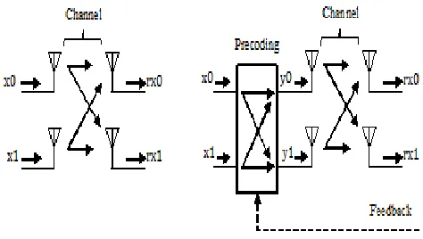
[image:3.612.326.563.226.360.2](1) MIMO and precoding: A standard 2×2 MIMO spatial multiplexing scheme, shown in Figure 1(a), assumes the wireless channel will provide four separate connections between transmit and receive antennas. Depending on the resulting channel conditions, the MIMO system may not be able to properly recover the transmitted data streams (layers) if the SNR is too low at any of the receive antennas.
Figure 1: Simplified block diagram showing the difference between (a) MIMO without precoding (b) MIMO with precoding
With the addition of Precoding, as shown in Figure 1(b), the transmitter, having knowledge of the current channel conditions, can effectively combine the layers before transmission with the goal of equalizing the signal reception across the multiple receive antennas. Precoding schemes have been specified for spatially-multiplexed and transmit-diversity applications [11].
This paper will examine precoding in Alamouti STBC systems. Precoding is based on transmit beam-forming concepts with the provision of allowing multiple beams to be simultaneously transmitted in the MIMO system. The LTE specification defines a set of complex weighting matrices for combining the layers before transmission using up to 4×4 antenna configurations [12]. For a 2×2 configuration, the weighting matrix, W, is multiplied by the input layers to generate the precoded signals to be transmitted.
[𝑦 (0)(𝑖)
𝑦(1)(𝑖)] = 𝑊(𝑖) [ 𝑥(0)(𝑖)
𝑥(1)(𝑖)] (5)
Here, 𝑥(𝑞)(𝑖) are the input layers prior to precoding (q =
0, 1) and 𝑦(𝑞)(𝑖) are the precoded signals applied to each
transmit antenna.
International Journal of Emerging Technology and Advanced Engineering
Website: www.ijetae.com (ISSN 2250-2459, ISO 9001:2008 Certified Journal, Volume 4, Issue 12, December 2014)
471
obtain in wireless; only incomplete or partial channel information is available to the transmitter. Instantaneous CSIT can be characterized by a channel estimate and an associated error covariance [13]. Both quantities are dependent on the delay in acquiring CSIT. As delay increases, the CSIT approaches the channel statistics [14]. Thus, both instantaneous and statistical CSIT can be expressed in the same form: a channel estimate, and an error or channel covariance.
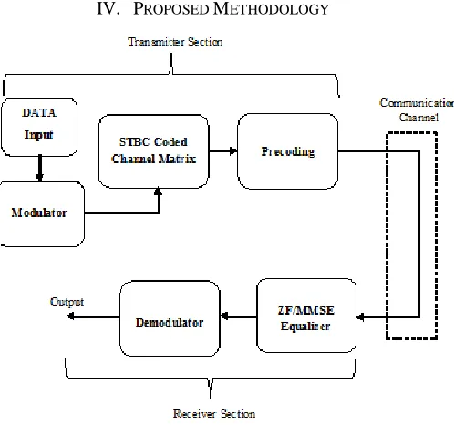
[image:4.612.51.300.252.485.2]IV. PROPOSED METHODOLOGY
Figure 2: Block diagram of proposed system.
Figure 2 shows the basic block diagram for proposed system. In transmitter section, binary sequence is inserted as input data and modulation is done in the next block. In present work, BPSK modulation scheme is employed. In the next section modulated data gets encoded by space time block coding technique and propagated to precoder for multiplication with codeword. Through appropriate channel, data is sourced to receiver section. Some noise content is also added to the data while conveying into the channel. In receiver section, equalizers are used to remove the impairments of channel. Finally, demodulator is used to recover original data in output. Here rotational precoding is used which is explained in the following section.
A. Rotational Precoding
Precoding, when the codebook stored at both ends is obtained by quantizing rotational manifold is commonly
referred to as rotational precoding. The main aim of rotational precoding is to direct all the power to the sub-streams along their corresponding Eigen directions of the channel, which can be achieved by the selection of appropriate codeword from the set that minimizes the distance,
𝑑(𝑊𝑘, 𝑊𝑙) = 1
√2||𝑊𝑘𝑊𝑘
𝐻− 𝑊
𝑙𝑊𝑙𝐻||𝐹 (6)
Where d is the chordal distance. The distance between two points located on a curve is known as chordal distance.
B. Precoded STBC
Figure 3: MIMO system model with Precoder.
Figure 3 shows MIMO system model with Precoder. M is the precoding matrix, Z is the equalizer, the stream 𝑥̃ is processed, split into several sub-streams, pre-multiplied with codeword and transmitted. 𝑦̃ is output.
Consider the MIMO system with 𝑁𝑇 antennas, that is h ∈ C1×NT. Let C ∈ CM×Tdenote a space-time codeword with a length of M, which is represented as:
C = [c1c2… … cT] (7)
Where
ck= [ck,1ck,2… … ck,M]T, k = 1,2, … . . , T and M ≤ NT (8)
[image:4.612.330.576.297.477.2]International Journal of Emerging Technology and Advanced Engineering
Website: www.ijetae.com (ISSN 2250-2459, ISO 9001:2008 Certified Journal, Volume 4, Issue 12, December 2014)
472
F = {W1, W2, W3… , WL} (9)
The objective is to choose an appropriate codeword that improves the overall system performance such as channel capacity or error performance. Assuming that NT channels remain static over T, the received signal y ∈ C1×T can be
expressed as,
y = √ENX
ThWC + z (10)
In above equation the length of each vector is 𝑀 ≤ NT.
The probability of codeword error can be derived as follows: For a given channel ℎ and precoding matrix W, we consider the pair wise codeword error probability Pr(Ci→ Cj|H|).
The upper bound of the pair wise error probability is given as:
Pr(Ci→ Cj|H|) = Q (√
𝜌||𝐻𝑊𝐸𝑖,𝑗||𝐹2
2NT ) ≤ 𝑒𝑥𝑝 (−
𝜌||𝐻𝑊𝐸𝑖,𝑗||𝐹2 4NT )
(11)
Where ρ is the signal-to-noise ratio (SNR), given as 𝜌 = 𝐸𝑥/𝑁0 and 𝐸𝑖,𝑗is the error matrix between the codewords 𝐶𝑖
and 𝐶𝑗 which is defined as 𝐸𝑖,𝑗= 𝐶𝑖− 𝐶𝑗 for a given STBC
scheme. From equation above we see that ||𝐻𝑊𝐸𝑖,𝑗||𝐹2 needs
to be maximized in order to minimize the pairwise error probability. This leads us to the following codeword selection criterion:
𝑊𝑜𝑝𝑡= arg 𝑚𝑎𝑥⏟ 𝑊∈𝐹,𝑖≠𝑗
||𝐻𝑊𝐸𝑖,𝑗||𝐹2
= arg max⏟ W∈F,i≠j
Tr(HWEi,jEi,jHWHHH)
= arg 𝑚𝑎𝑥⏟ 𝑊∈𝐹
𝑇𝑟(𝐻𝑊𝑊𝐻𝐻𝐻)
= arg 𝑚𝑎𝑥⏟ 𝑊∈𝐹
||𝐻𝑊||𝐹2 (12)
In the course of deriving equation (12), we have used the fact that the error matrix of STBC has the property of
𝐸𝑖,𝑗𝐸𝑖,𝑗𝐻 = 𝑎𝐼 with constant 𝑎. When the constraint 𝑊𝜖 𝐹 is
not imposed, the above optimum solution 𝑊𝑜𝑝𝑡 is not
unique, because ||𝐻𝑊𝑜𝑝𝑡||𝐹2 = ||𝐻𝑊
𝑜𝑝𝑡𝑍||𝐹2. Where Z is a
unitary matrix. The unconstrained optimum solution of equation (12) can be obtained by singular value decomposition (SVD) of channel 𝐻 = 𝑈Σ𝑉𝐻, where the
diagonal entry of S is in descending order. It is shown that
the optimum solution of above equation is given by the leftmost M columns of V, that is,
𝑊𝑜𝑝𝑡= [𝑣1𝑣1… . . 𝑣𝑀] ≜ 𝑉̅ (13)
Since 𝑉̅ is unitary, 𝜆𝑖(𝑊𝑜𝑝𝑡) = 1, 𝑖 = 1,2, … , 𝑀
where 𝜆𝑖 (𝐴) denotes the 𝑖𝑡ℎlargest eigen value of the
matrix 𝐴.
In case that a channel is not deterministic, the following criterion is used for the codebook design:
𝐸 {𝑚𝑖𝑛⏟ 𝑊∈𝐹
( ||𝐻𝑊𝑜𝑝𝑡||𝐹2− ||𝐻𝑊||𝐹2)} (14)
Where the expectation is with regards to the random channel H. 𝑊𝑜𝑝𝑡 in equation (14) follows from equation (13)
for the given channel H.
The above expected value in equation (14) is upper-bounded as
𝐸 {𝑚𝑖𝑛⏟ 𝑊∈𝐹
(||𝐻𝑊𝑜𝑝𝑡|| 𝐹 2
− ||𝐻𝑊||𝐹2)} ≤
𝐸{𝜆12{𝐻}}𝐸 {𝑚𝑖𝑛⏟ 𝑊∈𝐹 1 2||𝑉̅𝑉̅
𝐻− 𝑊𝑊𝐻||
𝐹 2
} (15)
Since 𝜆12{𝐻} is given, the codebook must be designed so as
to minimize,
𝐸 {𝑚𝑖𝑛⏟ 𝑊∈𝐹 1 2||𝑉̅𝑉̅
𝐻− 𝑊𝑊𝐻||
𝐹 2
} in equation (15).
C. Equalization Techniques
(1) Zero Forcing Equalizer: Zero Forcing Equalizer is a linear equalization algorithm used in communication systems; it modifies the frequency response of the channel. The name Zero Forcing relates to cutting down the Inter Symbol Interference (ISI) to focus in a noise free case.
Consider a 2×2 MIMO channel, the mathematical statement might be expressed in matrix notation as:
(𝑦𝑦1 2) = (
ℎ11 ℎ21
ℎ12 ℎ22
) (𝑥𝑥1 2) + (
𝑛1
𝑛2) (16)
International Journal of Emerging Technology and Advanced Engineering
Website: www.ijetae.com (ISSN 2250-2459, ISO 9001:2008 Certified Journal, Volume 4, Issue 12, December 2014)
473 𝐻𝐻𝐻 = (ℎ11
∗
ℎ12 ∗
ℎ21 ∗
ℎ22 ∗) (
ℎ11 ℎ12
ℎ21 ℎ22 )
= [ |ℎ11| 2+ |ℎ
21|2 ℎ11∗ℎ12+ ℎ21∗ℎ22 ℎ12
∗
ℎ11+ ℎ22 ∗
ℎ21 |ℎ12|2+ |ℎ22|2
] (17)
(2) MMSE Equalizer: Minimum Mean Square Error (MMSE) approach alleviates the noise enhancement problem by taking into consideration the noise power when constructing the filtering matrix using the MMSE performance-based criterion.
The MMSE approach tries to find a coefficient W which minimize the criterion [9],
𝐸 {[𝑊𝑦−𝑥][𝑊𝑦−𝑥] 𝐻
} (18)
On solving,
𝑊 = (𝐻𝐻𝐻 + 𝑁
0𝐼)−1𝐻𝐻 (19)
When comparing to the equalization, apart from the 𝑁0𝐼
term both the equations are comparable. When the noise term is zero, the MMSE equalization reduces to ZF equalizer.
V. SIMULATION STUDY AND RESULTS
A. Evaluation Parameters
TABLE I
EVALUATION PARAMETERS
Number of constellation points 2
SNR range 0:3:21
Sampling frequency 1 MHz
Frequency of modulated signal 1 MHz
Number of data packets 10000
Modulation scheme BPSK
Equalizer used ZF, MMSE
Precoder type Rotational based
Space time coding Alamouti, OSTBC
Table I shows the evaluation parameters which are to be involved in the coding to enhance the BER performance of proposed system.
B. Results
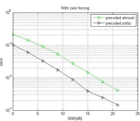
Figure 4: Comparison of BER performance of precoded Alamouti and precoded OSTBC with Zero forcing equalizer.
[image:6.612.327.563.189.393.2]Figure 4 shows the BER performance of the precoded Alamouti and precoded OSTBC with Zero forcing equalizer. It was found that the precoded OSTBC gives better BER performance as compared to precoded Alamouti.
[image:6.612.44.293.480.694.2] [image:6.612.328.561.483.672.2] [image:6.612.45.296.484.694.2]International Journal of Emerging Technology and Advanced Engineering
Website: www.ijetae.com (ISSN 2250-2459, ISO 9001:2008 Certified Journal, Volume 4, Issue 12, December 2014)
474
[image:7.612.51.287.189.378.2]Figure 5 shows the BER performance of the precoded Alamouti and precoded OSTBC with MMSE equalizer. It was found that the precoded OSTBC gives better BER performance as compared to precoded Alamouti.
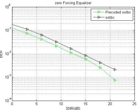
Figure 6: Comparison of BER performance of precoded OSTBC and OSTBC with Zero forcing equalizer.
[image:7.612.51.288.473.660.2]Figure 6 shows the BER performance of the precoded OSTBC and OSTBC with Zero forcing equalizer. It was found that the precoded OSTBC gives better BER performance as compared to OSTBC
.
Figure 7: Comparison of BER performance of precoded OSTBC and OSTBC with MMSE equalizer.
Figure 7 shows the BER performance of the precoded OSTBC and OSTBC with MMSE equalizer. It was found
that the precoded OSTBC gives better BER performance as compared to OSTBC.
VI. CONCLUSION
Space time block codes are proven to be spectral efficient with high bit error rate performance. In communication system, it is assumed that only receiver has the complete channel knowledge. If this channel knowledge can also be deployed at the transmitter end, the overall system performance can be pulled up to a great extent. Several techniques are presented in the literature that deploy this channel condition knowledge in terms of Channel State Information (CSI) at the transmitter. Some methods are based on limited bit feedback system which are spectrally inefficient while other technique is to represent channel conditions in terms of code-words which can be either transmitted or manipulated the transmitted data according to channel condition.
Rotational precoder based codebook method is evaluated in this paper over Space Time Block Coded and Orthogonal Space Time Block Coded system with Zero Forcing and MMSE equalizers.
Results show that deploying CSI at transmitter end amplifies the system performance. Moreover OSTBC-based precoded system is most spectral efficient.
References
[1] Bingham, J. A. C., “Multicarrier modulation for data transmission: An idea whose time has come,” IEEE Communication Mag., vol. 5, pp. 5-14, March 1990.
[2] Ke-Lin Du, M. N. S. Swamy, “Wireless Communication Systems”, Cambridge University Press, April, 2010.
[3] Ramjee Prasad, “OFDM for Wireless Communications Systems”, Artech House, January 2004.
[4] Li, Zhefeng. Space-time/frequency coded mimo and cooperative OFDM systems. Diss. University of Delaware, 2010.
[5] Helmut Bölcskei, Eth Zurich, “MIMO-OFDM Wireless Systems: Basics, Perspectives, and Challenges”, IEEE Wireless Communications, August 2006.
[6] KARACAYIR, MURAT. SPACE-TIME CODES. Diss. MIDDLE EAST TECHNICAL UNIVERSITY, 2010.
[7] S. M. Alamouti, “A simple transmit diversity technique for wireless communications,” IEEE J. Sel. Areas Commun., vol. 16, no. 8, pp. 1451-1458, Oct. 1998.
International Journal of Emerging Technology and Advanced Engineering
Website: www.ijetae.com (ISSN 2250-2459, ISO 9001:2008 Certified Journal, Volume 4, Issue 12, December 2014)
475 [9] Pandit, Mr Ankit, Mr SJ Basha, and Mr KK Sharma. "BER Analysis
of Various STBC Coding for MIMO Systems at Different Modulation Schemes." Space (Antenna) 1: 2.
[10]Yu Fu, W. A. Krzymien and C. Tellambura, “Precoding for Orthogonal Space-Time Block-Coded OFDM Downlink: Mean or Covariance Feedback?”, IEEE Transactions on Vehicular Technology, ISSN: 0018-9545, Vol. 58, Issue 7, pp. 3263-3270, September 2009.
[11]B. Zerlin, M. Joham, W. Utschick, and J. A. Nossek, “Covariance based linear precoding,” IEEE J. Sel. Areas Commun., vol. 24, no. 1, pp. 190-199, Jan. 2006.
[12]3rd Generation Partnership Project; Technical Specification Group
Radio Access Network; Evolved Universal Terrestrial Radio Access (E-UTRA); Physical Channels and Modulation (Release 8), 3GPP TS 36.211 V8.4.0, 2008.
[13]G. Barriac and U. Madhow, “Space–time precoding for mean and covariance feedback: Application for wideband OFDM,” IEEE Trans. Commun., vol. 54, no. 1, pp. 96-107, Jan. 2006.