Single mode lasers based on slots suitable for
photonic integration
Qiaoyin Lu,1,* Weihua Guo,2 Marta Nawrocka,1 Azat Abdullaev,1 Chris Daunt,3 James O’Callaghan,3 Michael Lynch,1 Vincent Weldon,1 Frank Peters,3 and John F. Donegan1
1School of Physics, Trinity College Dublin, Dublin 2, Ireland
2Department of Electrical & Computer Engineering, University of California Santa Barbara, California 93106, USA 3Tyndall National Institute, University College Cork, Ireland
*
Abstract: The re-growth free single mode lasers based on etched slots suitable for photonic integration are presented in this paper. The fabricated 650µm long laser exhibits a threshold current and a slope efficiency of about 32mA and 0.12mW/mA, respectively. The stable single mode operation has been observed with a side mode suppression ratio (SMSR) over 50dB at a current injection of 100mA for the fabricated laser. Such a laser integrated with electroabsorption (EA) modulator is also demonstrated. The integrated device has an extinction ratio over 10 dB at 2.2V driving voltage with the lasing wavelength of around 20nm positive detuning relative to the gain peak. The bandwidth measured is about 3GHz for the integrated device.
©2011 Optical Society of America
OCIS codes: (250.0250) Optoelectronics; (250.3140) Integrated optoelectronic circuits; (250.5590) Quantum-well, -wire and -dot devices; (250.5960) Semiconductor lasers.
References
1. R. D. Martin, S. Forouhar, S. Keo, R. J. Lang, R. G. Hunsperger, R. C. Tiberio, and P. F. Chapman, “CW performance of an InGaAs-GaAs-AlGaAs laterally-coupled distributed feedback (LC-DFB) ridge laser diode,” IEEE Photon. Technol. Lett. 7(3), 244–246 (1995).
2. J. Wang, J.-B. Tian, P.-F. Cai, B. Xiong, C.-Z. Sun, and Y. Luo, “1.55µm AlGaInAs-InP laterally coupled distributed feedback laser,” IEEE Photon. Technol. Lett. 17(7), 1372–1374 (2005).
3. S. J. Jang, J. S. Yu, and Y. T. Lee, “Laterally coupled DFB lasers with self-aligned metal surface grating by holographic lithography,” IEEE Photon. Technol. Lett. 20(7), 514–516 (2008).
4. R. M. Lammert, J. S. Hughes, S. D. Roh, M. L. Osowski, A. M. Jones, and J. J. Coleman, “Low-threshold narrow-linewidth InGaAs-GaAs ridge-waveguide DBR lasers with first-order surface gratings,” IEEE Photon. Technol. Lett. 9(2), 149–151 (1997).
5. J. Fricke, F. Bugge, A. Ginolas, W. John, A. Klehr, M. Matalla, P. Ressel, H. Wenzel, and G. Erbert, “High-Power 980-nm Broad-Area Lasers Spectrally Stabilized by Surface Bragg Gratings,” IEEE Photon. Technol. Lett. 22(5), 284–286 (2010).
6. B. Corbett and D. McDonald, “Single longitudinal mode ridge waveguides 1.3µm Fabry–Perot laser by modal perturbation,” Electron. Lett. 31(25), 2181–2182 (1995).
7. J. Patchell, D. Jones, B. Kelly, and J. O’Gorman, “Specifying the wavelength and temperature tuning range of a Fabry-Perot laser containing refractive index perturbations,” Proc. SPIE 5825, 1–13 (2005).
8. S. O’Brien and E. P. O’Reilly, “Theory of improved spectral purity in index patterned Fabry-Perot lasers,” Appl. Phys. Lett. 86(20), 201101 (2005).
9. B. Kelly, R. Phelan, D. Jones, C. Herbert, J. O’Carroll, M. Rensing, J. Wendelboe, C. B. Watts, A.
Kaszubowska-Anandarajah, P. Perry, C. Guignard, L. P. Barry, and J. O’Gorman, “Discrete mode laser diodes with very narrow linewidth emission,” Electron. Lett. 43(23), 1282–1284 (2007).
10. L. P. Barry, C. Herbert, D. Jones, A. Kaszubowska-Anandarajah, B. Kelly, J. O’Carroll, R. Phelan, P. Anandarajah, K. Shi, and J. O’Gorman, “Discrete mode lasers for communications applications,” Proc. SPIE
7230, 72300N, 72300N-12 (2009).
11. S. O’Brien, F. Smyth, K. Shi, J. O’Carroll, P. M. Anadarajah, D. Bitauld, S. Osborne, R. Phelan, B. Kelly, J. O’Gorman, F. H. Peters, B. Boycroft, B. Corbett, and L. P. Barry, “Design, characterization, and applications of index-patterned Fabry-Perot Lasers,” IEEE. J. Sel. Topics. Quantum. Electron., PP, 1–11 (2011).
13. J. P. Engelstaedter, B. Roycroft, and B. Corbett, “Laser and detector using integrated reflector for photonic integration,” Electron. Lett. 44(17), 1017–1019 (2008).
14. Q. Lu, W.-H. Guo, D. Byrne, and J. F. Donegan, “Design of slotted single mode lasers suitable for photonic integration,” IEEE Photon. Technol. Lett. 22(11), 787–789 (2010).
15. A. Ramdane, F. Devaux, N. Souli, D. Delprat, and A. Ougazzaden, “Monolithic integration of multiple-quantum-well lasers and modulators for high-speed transmission,” IEEE J. Sel. Top. Quantum Electron. 2(2), 326–335 (1996).
1. Introduction
Realizing single mode lasers with very simple fabrication has attracted strong continued interest among groups all over the world. No regrowth is a key pre-requisite for the so-called simple fabrication. Laterally coupled DFB lasers [1–3] and surface-grating distributed Bragg reflector (DBR) lasers [4,5] which use just a single growth step have thus attracted great interest. However, these devices generally need electron-beam lithography for patterning which is quite expensive and time consuming compared with the standard photolithography.
An exception is the slotted laser reported in [6–13]. These lasers use optical defects in a standard Fabry-Pérot (FP) laser to specifically select a single mode, and such optical defects are formed by etching around 1 µm wide slots into the top ridge of the laser waveguide. Generally multiple slots have to be etched, of which the reflection strength determines how different the selected mode is from other modes, and the reflection band determines which mode is selected. These slots, if we consider them as a kind of grating, are generally very high order surface gratings. Up to now there have been two types of laser schemes based on these slots: one is the mode selective FP laser type [6–11], where the slots are seated inside the laser cavity. This type of laser needs two cleaved facets to form the fundamental FP cavity and uses the slots to select one single mode from the multiple modes of the FP cavity. The threshold of such a laser is mainly determined by the fundamental FP cavity. However, because it needs two cleaved facets it cannot be employed to integrate monolithically with other optical devices. Another is the high-order distributed Bragg reflector (DBR) laser type [12,13], where the slots are introduced into one side of the laser cavity to provide the full feedback for lasing. This type of laser is made completely dependent on slots. Because in this way the fundamental FP cavity is removed, the strong background reflection from the FP cavity facets disappears, which means that the laser can be integrated with other photonic devices such as electro-absorption (EA) modulators and mode converters, and that the laser can potentially work over a wide temperature range while keeping high side mode suppression ratio (SMSR). In [13] a laser based on the very deep slots has been demonstrated to integrate with a photodiode, however, this laser suffered from a low SMSR due to the broad reflection bandwidth caused by the small number of deep slots. By optimizing the slot width, depth and period, we predicted in theory that single mode lasers can be made completely dependent on such slots at one end of the laser cavity and in such case the laser is suitable for photonic integration [14]. In this paper we present the design, fabrication and experimental results on this non-regrowth integrable single mode laser based on slots. The laser integrated with EA modulators using identical active layer (IAL) [15] is also demonstrated.
2. Design of Single Mode Lasers Based on Slots
approximation the three dimensional ridge waveguide is simplified into a 2D structure as shown in Fig. 1 (b).
Fig. 1. (a) 3D schematic structure of the slotted single mode laser integrated with the EA modulator. (b) Simplified 2D waveguide structure with the slot.
The slot parameters such as the slot width ds, spacing dw, depth, and slot number are key
parameters which influence the laser performance and have to be optimized in the design. To optimize these slot parameters, the 2D scattering matrix method (SMM) is used for the simulation. The slot depth was first set as 1.35µm, which is much smaller than the 1.85µm ridge height, to seek a high reflection while keeping a narrow reflection bandwidth. The slot width and slot spacing are defined as ds = (2p+1)λB/4ns and dw = (2q+1)λB/4nw, respectively,
where p and q are integers, ns and nw are the effective index of the slot region and the
waveguide region, λB is the Bragg wavelength which is always set to be 1550 nm in the
simulation.
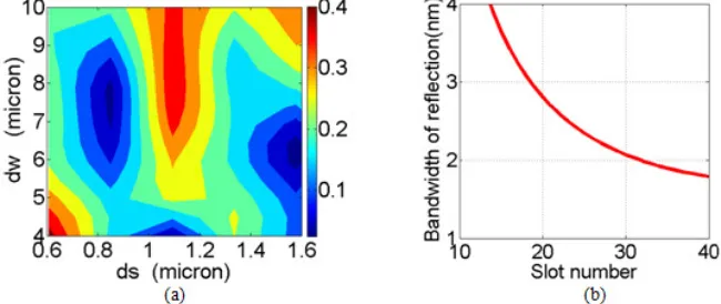
Fig. 2. (a) Contour plot of calculated amplitude reflection versus slot width and spacing. (b) Calculated reflection bandwidth versus slot number.
[image:3.612.192.429.101.301.2] [image:3.612.142.467.442.579.2]required to ensure a good single mode operation. Figure 2 (b) shows the 3-dB bandwidth of the reflection spectrum versus the slot number, which shows that when the slot number is between 20 and 30, a reflection bandwidth narrower than 3 nm can be obtained, which would cover 2 to 3 longitudinal modes of a conventional FP laser with a 300µm cavity length.
By increasing the slot number a sufficiently high reflection can be obtained but with a sacrifice of the transmission due to the loss caused by each slot. From the above analysis, the slots are optimized with a slot number of 24. For such slots, an amplitude reflection and transmission around 0.43 and 0.4, respectively, can be generated, and the bandwidth is around 2.5nm. This will help to achieve good single mode operation with a minimum laser threshold.
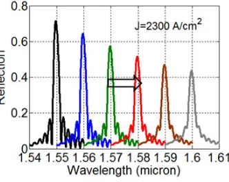
[image:4.612.139.474.285.420.2]For a group of slots with uniform slot period of around 9µm, the calculated free spectral range (FSR) is around 37nm, which means there are three reflection peaks in the wavelength range from 1500nm to 1600nm as shown in Fig. 3 (a). For integration with EA modulators which use the same quantum well layer as for the active region of the laser, the laser wavelength need to be red shifted from the gain peak. Therefore we need to suppress the side reflection peaks in the design. Simply we introduce three slot periods (8.5, 9.9 and 11.4µm) to eliminate the side reflection peaks as shown in Fig. 3(a), where nearly no overlap among the side peaks. Figure 3 (b) shows the calculated reflection spectrum from such a group of slots, where the central reflection peak dominates.
Fig. 3. Calculated reflection spectrum from a group of 24 slots (a) with the slot period of 8.5, 9.9 and 11.4 µm, respectively. (b) with three above slot periods.
Fig. 4. Calculated red shift reflection spectrum.
[image:4.612.224.390.453.585.2]3. Device Fabrication and Characteristics
For the first fabrication run e-beam lithography was used to pattern the slot but potentially photolithography can be used considering the ~1.0 µm slot width. Two steps of inductively coupled plasma (ICP) based dry etching with Cl2 /N2 gas combinations were used to form the
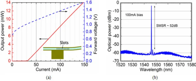
ridge and the slots. First a 0.5µm high surface ridge was formed with the slot area being protected during the dry etching. Afterwards the protection layer was removed and a second dry etching was used to form the slot and also to continue etching the ridge to a depth of 1.85µm. The slot was thus about 0.5µm shallower than the ridge as was determined by this two-step dry etching process. The ridge was then passivated and metal contacted to finish the device structure. Finally the fabricated devices were cleaved and mounted on silicon carriers and placed on a thermoelectric cooling (TEC) unit to hold at a constant temperature of 25þ C during the measurement. The fabricated laser has a total cavity length of 650 µm which includes the 235 µm long section between the back facet and the first slot, and the 215 µm long slot section and the 200 µm long curved front SOA (it is curved to produce a 7 degree angle with respect to the cavity and thereby to eliminate the back reflection from the front facet). A stable single mode performance with a threshold current of about 32mA and a slope efficiency of about 0.12mW/mA has been observed for this laser, as shown in Fig. 5 (a). Figure 5 (b) is the measured output spectrum at an injection current of 100mA, which shows a side mode suppression ratio of about 52dB.
Fig. 5. (a) Measured light-current-voltage (LIV) curves at 25þC. The inset shows laser structure. (b) Measured output spectrum at 100mA for 650µm long integrable slotted single mode lasers.
[image:5.612.135.475.303.445.2]Fig. 6. (a) Measured output spectrum from the EA side facet. The inset shows laser-EA structure. (b) Normalized output power versus the reverse bias of EA modulator.
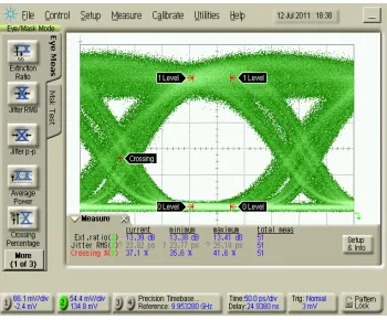
[image:6.612.134.475.75.220.2]The bandwidth of the integrated device is measured to be over 3GHz as shown in Fig. 7. The bandwidth is limited by the simple contacting arrangement to the device. Much higher bandwidths can be envisaged through an optimized contacting arrangement.
Fig. 7. Measured eye diagram at 3Gb/s.
4. Conclusion
A re-growth free single mode laser scheme based on slots suitable for photonic integration has been presented. The fabricated lasers exhibit a stable single mode operation with a threshold of 32mA and side mode suppression ratio of about 52dB. Such laser integrated with EA modulator has also been demonstrated. The integrated device has a lasing wavelength of around 1569nm (20nm red shift from the gain peak). A DC extinction ratio of 10dB and 3dB bandwidth of 3GHz have been observed for the integrated devices. The laser performance can be further improved in terms of output power and threshold current if the back-side facet can be HR coated. The presented laser structure just needs a single wafer growth and can be fabricated by standard photolithography, which should provide a significant cost advantage.
Acknowledge
[image:6.612.219.394.289.434.2]