Analysis & Design, implementation of Electrical Power System THD
(Total Harmonic Distortion) by Virtue of Fast Fourier Transform in
Discrete Signal Processing
Saurabh Sharma
1Manoj Kumar Dewangan
2 1M. Tech Scholar
2Assistant Professor
1,2
Department of Electrical Engineering
1,2
VEC, Lakhanpur, Ambikapur (C.G.), India
Abstract— The objective of electricity utility is to deliver AC voltage at fairly constant magnitude throughout their system. However a difficulty occurred by the FACT that there are loads on the system that produce harmonics currents, which result in distorted voltage and current that can adversely impact the power system performance in different ways. Therefore detection is essential to describe such event. One of the methods to detect harmonics is Fast Fourier Transform (FFT). The FFT plays important roles in the analysis, design, and implementation of discrete signal processing. FFT algorithms are based on fundamental of discrete Fourier computation. Such algorithms are more efficient than the discrete Fourier transform.
Keywords: Fast Fourier Transform (FFT), THD (Total Harmonic Distortion), Discrete Signal Processing
I. INTRODUCTION
It is well known that nonlinear loads produce harmonics which could have serious effects to sensitive electrical devices.Power harmonics problems likely to be experienced in any particular location are largely unknown because only few statistics published. That’s why customers are difficult to quantify the cost of failure equipment. Customer who are likely to suffer from power harmonics problems depend on: (a) quality of voltage supplied by power provider, (b) Different type of loads and (c) sensitivity of customer own equipment. Therefore Total harmonics Distortion detection needs to be done.
These days electrical power system has been inter-disciplinary among power plant engineering and other areas such signal processing and computer vision. This paper is collaboration of power and discrete signal processing. The harmonics distortion is simulated in Mat lab environment and then fast Fourier transform(FET) tools is used for analyzing and breakdown the harmonic signals into its different frequency component.
A. What is Harmonics?
A harmonic is a signal or wave whose frequency is an integral (whole-number) multiple of the frequency of some reference signal or wave.
Distortion is the alteration of the original shape (or other characteristic) of something, such as an object, image, sound or waveform.
1) Harmonic Distortion:
Alteration in sinusoidal waveform.
B. Power System Harmonics:
1) Voltage Harmonics 2) Current Harmonics
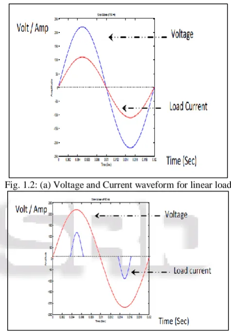
Fig. 1.2: (a) Voltage and Current waveform for linear load
Fig. 1.2: (b) Voltage and Current waveform for linear load To fully appreciate of the harmonic distortion effect, there are two important concepts to keep in mind with regard to harmonics. Firstly, the nature of harmonic current that produced by loads (non-linear loads), and secondly, the way in which harmonic currents flow and how the harmonic voltage developed in power system.
[image:1.595.307.545.174.516.2]This voltage produces voltage distortion. If the source impedance is low then the voltage distortion will be low. However, if a significant of the load becomes increase and or system impedance increase, voltage distortion could increase dramatically.
Fig. 1.2: (c) Distorted current and voltage
C. Why Harmonics Analysis:
When a voltage and/or current waveform is distorted, it causes abnormal operating conditions in a power system such as:
1) Voltage Harmonics can cause additional heating in induction and synchronous motors and generators. 2) Voltage Harmonics with high peak values can weaken
insulation in cables, windings, and capacitors.
3) Voltage Harmonics can cause malfunction of different electronic components and circuits that utilize the voltage waveform for synchronization or timing. 4) Current Harmonics in motor windings can create
Electromagnetic Interference (EMI).
II. THEORETICAL BACKGROUND
A. Harmonic Sources
1) Current Source Nonlinear Load 2) Voltage Source Nonlinear Load 1) Current Source Nonlinear Load
Thyristor rectifier for DC drives, Heater Drives etc.
Fig. 2.1: (a)
2) Voltage Source Nonlinear Load
Diode Rectifier For AC Drives, Electronic Equipment etc.
Fig. 2.1: (b)
Converters
Devices which includes semiconductor elements
Generators
Motors
Transformers
Lightening equipments working by gas discharge principle
Photovoltaic system
Computers
Electronic ballast
Uninterruptable power supplies
Switching power supplies
Arc Furnace
Welding machine
Control Circuit
Static Var Compensators
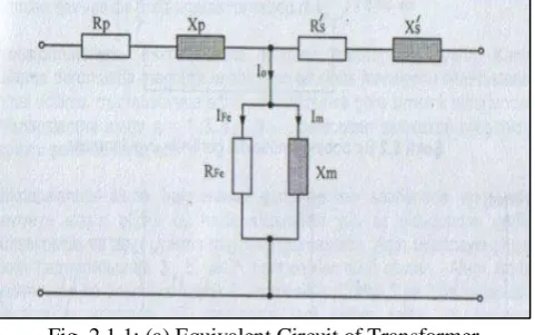
1) Transformer
[image:2.595.304.550.78.495.2]Transformers are the most important elements in power system and oldest nonlinear elements known. The magnetization characteristic of transformer’s core is nonlinear and produce harmonics as it is saturated.
[image:2.595.50.286.136.270.2] [image:2.595.57.430.330.758.2] [image:2.595.310.551.577.727.2]resistance and leakage reactance is negligible at low current. At any instant sinusoidal supply is given by
[image:3.595.46.289.105.577.2] [image:3.595.306.544.296.435.2] [image:3.595.308.553.583.724.2]V1= e1 = -em sin ɯt = N1 dɸ/dt ɸ = -ʃe1/N1 dt = Em/N1ɯ cosɯt = ɸm cosɯt
[image:3.595.46.289.625.742.2]Fig. 2.1.1: (b)
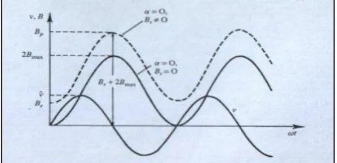
Fig. 2.1.1: (c) Voltage, Magnetic Flux Density and Magnetic Flux
Fig. 2.1.1: (d) Current waveform Br+2Bmax (almost three times the working flux).
This will produce excessive ampere turns in the core. This effect gives rise to magnetizing current up to 5-10 per unit of the rating shown in fig below
Fig. 2.1.1: (e) Inrush Harmonic Current
a) Triplen Harmonic current In Transformer:
I1 : Effective value of the fundamental component of a nonlinear and balanced load current
ɯ1 : angular frequency for the fundamental frequency The instantaneous value of the fundamental component of the load current for phases a,b and c is equal to
ia (t) 2I1 sin(1t) ib (t) 2I1 sin(1t 2/3) ic (t) 2I1 sin(1t 2/3)
For the nth harmonic component, instantaneous value of the currents for phases a,b and c is equal to
ian (t) 2I n sin(n1t)
Specific results can be seen from here for triplen harmonics. Assume k=1,2,3,… and the instantaneous value for n=3k order harmonic components (3,6,9,…). As seen from the equation above, under balanced load and network conditions, triplen harmonic component’s all three phase currents are equal to each other.
Fig. 2.1.1: (f) Triplen Harmonic Current
Harmonic currents flowing through the generator, the transmission line and the transformer reactance, causes harmonical voltage drops. The harmonics of the magnetisation currents can be blocked by the precautions taken during the design phase.
b) Star-Connected Transformers:
1) The Transformers Star Point is connected to Earth: The current flows through the neutral conductor will be zero because of the sum of the balanced fundamental component currents belong to the three phases is zero. This situation is not valid for triplen harmonics. The sum of the three phase currents flows through the neutral conductor as shown in the figure below.
Fig. 2.1.1(g) Star Connected power Transformer c) Delta-Connected Transformers:
1) Primary Circuit is Delta-Connected:
2) Secondary Circuit is Delta-Connected:
As the total current at the nodal points of the delta connection is equal to zero (figure below), triple harmonics do not flow through the network.
To summaries; Whatever
1) the connection group of the primary/secondary circuit is, 2) if the star point of the primary/secondary circuit is
connected or disconnected to Earth,
3) the core type of the transformer is 1,5,7,11,13 th … harmonic components occur in the network.
To mitigate the triple harmonics from the network, primary should not be earthed or one of the windings should be delta-connected. If the nonlinear load is unbalanced, whatever the transformer design is, triple harmonics will also flow through the network.
[image:4.595.307.548.99.397.2] [image:4.595.50.289.270.451.2] [image:4.595.49.289.513.756.2]2) Arcing Devices
Fig. 2.1.2: (a)
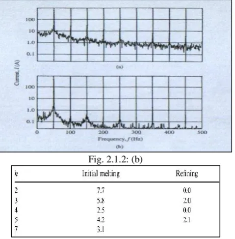
a) Arc Furnance
Harmonic produced between melting and refining stage. The arc furnance load gives the worst distortion, and due to physical phenomenon of the melting with a moving electrode and molten material the arc current wave may not be same from cycle to cycle.
[image:4.595.327.527.628.766.2]Fig. 2.1.2: (b)
Table 2.1.2: (a)
b) Discharge Type Lighting
Discharge type lighting is highly nonlinear and gives rise to considerable odd ordered harmonic currents.
Fig. 2.1.2: (c)
Fig. 2.1.2: (d)
Also the lightning ballasts connected to the lamp may produce large harmonic distortions and third harmonic currents in the neutral. The newer rapid start ballast has a much lower harmonic distortion and can be filtered with a filter circuit implementation. Table below shows the harmonic spectrum of a fluorescent lamp with a magnetic ballast. Harmonic currents are shown as the percentage of the fundamental component.
Table 2.1.2: (b)
3) Single Phase Rectification
Fig. 2.1.3: DC Supply
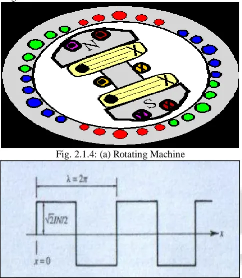
4) Rotating Machine Harmonics
Rotating machines produce harmonic due to the field distribution of salient pole, the magnetic permeance is related with slots and the saturation of the main circuit.
Harmonic currents developed due to
1) Asymmetries on the machine stator or rotor slots. 2) Irregularities in the winding patterns of three phase
winding.
[image:5.595.312.546.73.176.2]Additional harmonic current can be created upon magnetic core saturation.
[image:5.595.46.289.201.481.2]Fig. 2.1.4: (a) Rotating Machine
Fig. 2.1.4: (b) Frequency domain representation of the mmf space distribution
B. Discrete Signal Processing
Signal processing is discipline concerned with extracting, analyzing and manipulating information carried by signals. A signal is pattern of variation of a physical quantity as function of time, space, distance, position, temperature, pressure etc. These quantities are usually independent variables that define the signal itself. The processing method depends on what type of signal and on the nature of information carried by a signal. In fact, real signal are continuous or analogue which mathematically represented as time dependent functions or time domain representation. However through sampling by gathering data, then the corresponding frequencies of the signal can be discrete and bounded, shown in figure 1 below.
Fig. 2.2: Analogue and Discrete signal
X(t) represent analogue signal and X[n] represent discrete signal, where the time index n=0, 1, 2…. So that discrete time t = n × T period. During the process of gathering data, one can seriously affects the frequency content of the signal. This is true for superposition of signals with fixed frequencies. The situation becomes more complicated if the data has an overall non constant trend or exist in the presence of noise. In order to be able to analyze complex signal which have been developed. Perhaps the most popular method used is Fourier analysis.
Fourier analysis provides a set of mathematical tools which can be used to breakdown a signal into its various frequency components. Then it is possible to predict the effect of particular signal from previous knowledge of what effect of its individual frequencies component. This method works in frequency domain representation. Since duplicating mathematical steps of Fourier analysis in a microprocessor or computer based is reasonably difficult, thus needs compatible process which known as Discrete Fourier Transform (DFT) as discuss in the following section.
C. Discrete Fourier Transform(DFT)
Due to its basic properties, the DFT is convenient to analyze and design system in frequency domain. Computation of N point DFT corresponds to computation of N samples of Fourier transform at N equally space frequencies.
D. Fast Fourier Transform
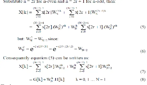
FFT algorithms are based on the fundamental principle of decomposing the DFT computation of a sequence of length N into successively smaller DFT. Such algorithms vary in efficiency but all of them require fewer multiplications and additions than direct DFT does. Algorithms in which decomposition is based on decomposing a sequence x [n] into successively smaller subsequence are called decimation in time algorithm. The basic idea is illustrated by considering special case of N as 2 to the power of a special integer, i.e. N
Each
summation in equation (8) is recognized as an (N/2)-point DFT where the first term G [k] is (N/2)-point DFT of even numbers and the second term H [k] is (N/2)-point DFT of odd numbers of original sequence. Figure 3 depicts this computation for N=8, with G [k] designating the 4-point DFT of even numbers and H [k] designating the 4-point DFT of odd numbers.
X [0] is obtained by multiplying H [0] by WN0 and adding the product to G [0] and so on. However, since G [k] and H [k] are both periodic in k with the period of 4, then H[4] = H [0] and G [4] = G [0]. Thus X [4] is obtained by multiplying H [0] by WN4 and adding the result to G [0]. Values of X [5], X [6] and X [7] are obtained similarly as shown in Figure 3. Therefore, for all values of k requires N + 2(N/2)2 or N + N2/2 complex multiplications and complex additions. It can be demonstrated that for N > 2, total computation of N + N2/2 will be less than N2 as in direct DFT computation. Each term in equation (8) can be break down into (N/4)-point DFT which then would be combine to yield the (N/2)-point DFT. Thus G [k] can be represented as:
[image:6.595.303.546.59.478.2]Thus, (N/2)-point DFT of G [k] can be obtained by combining (N/4)-point DFT of sequences g [2l] and g [2l + 1], as well as H [k] which shown in Figure 4.
Fig. 2.4.1: Flow graph of N-point DFT computation into (N/2)-point DFT computation for N=8
Fig. 2.4.2: Flow graph decomposition of (N/2) point DFT into Two (N/4)-point DFT computation for N=8.
E. Total Harmonic Distortion (THD):
Distortion gives a waveform which is non-sinusoidal but periodic. Such a waveform can be resolved into a fundamental voltage V1 and harmonics, they are V2, V3, V4, etc. Total harmonic distortion up to the 20th order are of interest in power systems as the higher order one that extremely small. In this case, the root mean square (RMS) of voltage V can be calculated using:
[image:6.595.44.285.79.219.2]1) Incorrect reading meters, including induction disc-type W-hrs meter and averaging type current or A-meters. 2) Reducing true power factor or PF, where PF = Watts/VA. 3) Overheating in transformer especially delta windings;
where harmonics generated on the load sides of a delta-Wye transformer may circulate in the primary sides. 4) Positive, negative and zero sequence voltages on motors.
These are voltages at particular frequency that rotate the motors forward, backward or neither just heat up the motors.
5) Trouble in operation of protective devices such as false tripping of relays and failure of uninterruptible power supply or UPS to transfer properly.
6) Bearing failure from shaft currents through un-isolated bearings of electric motors.
7) Blown fuses on power factor correction capacitors, due to high voltage and current as resonance with line impedance.
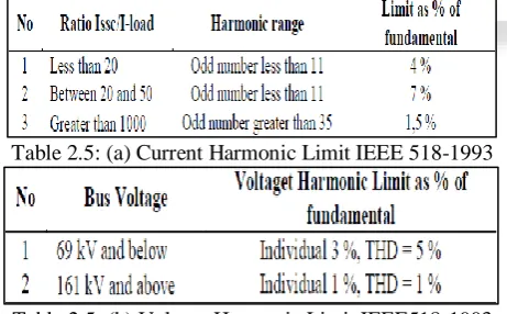
8) Pointless operation or failure of electronic equipment. To determine normal or acceptable level of harmonic, there are a number of standards have been developed. IEEE 519-1992 provides guidelines for determining the acceptable limits. For current, it is depending on ratio of short circuit current to average load current of maximum demand(MD) over 1 year, and for voltage, it is used to determine the various limits.
Harmonics can be calculated using a handheld-meter. However, harmonics values always change during the day, as different loads are turned on and off within a facility or others in the same network. This requires the use of a monitoring with harmonic capabilities which can record harmonic values o77VVVver a period of time.
Table 2.5: (a) Current Harmonic Limit IEEE 518-1993
Table 2.5: (b) Voltage Harmonic Limit IEEE518-1993
F. Principle of controlling harmonics
1) minimized harmonic current in various load. 2) Filtering.
3) By changing system frequency responses.
1) Harmonic controlling devices-
1) Active type series & shunt filter 2) Zigzag power transformer 3) Passive types series & shunt filter
G. Harmonic Analyzer
Total Harmonic Distortion (THD) Analyzers calculate the total harmonic content of AC with some distortion, expressed as total harmonic distortion (THD). A typical application is to determine the THD of an amplifier by using
a very-low-distortion sine wave input and examining the output.
There are several types of distortion analyzers: 1) Fundamental suppression
[image:7.595.305.551.93.319.2]2) Heterodyne type 3) Tuned circuit 4) Spectrum analyzer
Fig. 2.7: Fundamental suppression
III. SIMULATION
The general problem of fundamental frequency estimation is to take a portion of signal and to find the dominant frequency of repetition. Difficulties arise when signals may be contaminated with noise, even with periodic signals of other fundamental frequencies for instance power system harmonics signal. Fast Fourier transforms is a common used to find such frequency components when covered in a noisy time domain signal.
A. MAT LAB Syntax
This section provides the implementations of the Fast Fourier Transform (FFT) in Mat lab. The FFT function is part of the standard Mat lab language. The syntax FFT computes the discrete Fourier transform of a vector or matrix. y = fft(x) is the discrete Fourier transform of vector x, computed with a fast Fourier transform (FFT) algorithm. If x is a matrix, y is the FFT of each column of the matrix. y = FFT(x,n)is the n-point FFT. If the length of x is less than n, FFT pads x with trailing zeros to length n. If the length of x is greater than n, FFT truncates the sequence x. If x is an array, FFT adjusts the length of the columns in the same manner.
IV. RESULT AND ANALYSIS
[image:7.595.52.283.447.590.2]Fig. 4: (a)
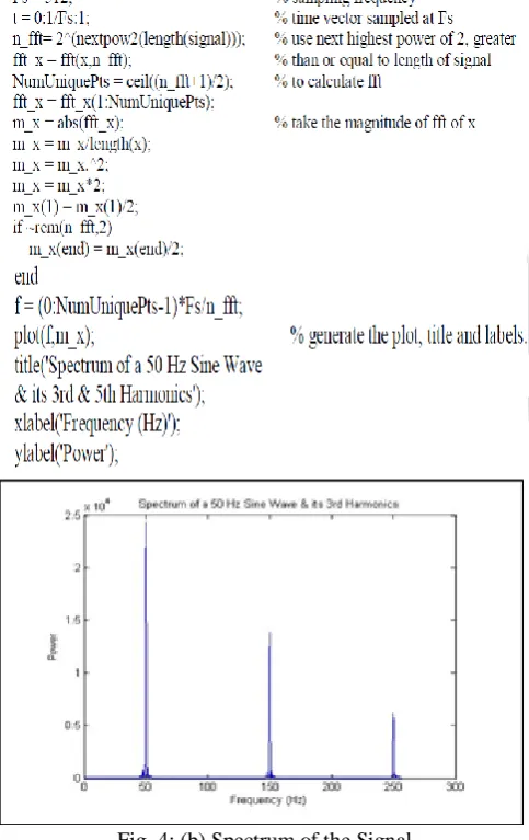
To identify that, Mat lab program with fft function is used to analyze the signal into various frequencies by assuming ‘x’ is the vector containing the data. The programs are as follow:
Fig. 4: (b) Spectrum of the Signal
V. CONCLUSION
The simulation study of fast FET has been presented in this paper for extracting various frequencies component of electrical power system harmonics. The function of FFT in MATLAB is a powerful tool for doing that even with noisy signals. The simulation result shows that 3rd and 5th harmonics could extract accurately and nicely by looking at
strong peaks on the graph produced by the FFT. The FFT is also work fine to breakdown the 7th, 9th, 11th, 13th, 15th, 17th, 19th and above of harmonics.
REFERENCES
[1] E.A. Cano Plata & H.E. Tacca. 2005. Power Load Identification. Journal of the Franklin Institute. (342) 97-113.
[2] Arrillaga J. & Watson N.R. 1985. Power System Quality Assessment. John Wiley & Sons Inc. New York. [3] J.B. Reddy & D.K. Mohanta, B.M. Karan. 2004. Power
System Disturbance Recognition Using Wavelet and S-Transform Techniques. International Journal of EEPS (1)1007.
[4] WilliamD.Stanley. 2005. Technical Analysis &
Applications with MATLAB.Thomson Delmar
Learning. Canada, pp. 429-446.
[5] Randall Shaffer. 2007. Fundamentals of Power Electronics with MATLAB.Thomson Delmar Learning. Boston-Massachusetts, pp. 33-36.
[6] Alan V. Oppenheim & Alan S. Willsky. 1983. Signals & Systems. 2nd ed. Prentice Hall. pp. 1-5 & 372-373. [7] Ashok Ambardar. 2007.Digital Signal Processing: A
[image:8.595.45.289.70.227.2] [image:8.595.46.288.275.659.2]