International Journal of Computer Applications (0975 – 8887) Volume 43– No.22, April 2012
ELMA based Design of SCMFIM to Improve the
Efficiency and Power Factor
S.S.Sivaraju
Department of Electrical and Electronics Engg, RVS College of Engineering and Technology,
Coimbatore, Tamilnadu, India.
N.Devarajan
Department of Electrical and Electronics Engg, Government College of Technology,
Coimbatore, Tamilnadu, India.
ABSTRACT
The squirrel-cage Induction motors (SCIMs) are approximately 80% of the overall electricity use in industrialized countries. In the agricultural and commercial sectors also, power consumption by high power SCIMs are quite substantial. On an average, the energy consumed by a motor during its life cycle is 40-80 times the initial cost of the motors. Therefore efficiency and power factor (PF) of the motor is very essential for both during design and operation. Even small increase in efficiency and power factor, improvement can make a big difference in energy savings in variable load applications. In this paper mainly focusing on op-timal design of multiple stator-winding to improve efficiency and power factor of high power SCIMs during variable loads, the different flux level of stator winding are designed [4] (star-delta) according to variable loads and its performance is discussed. The Extreme Learning Machine Algorithm (ELMA) is used for the multiple stator winding design and optimization process and the obtained simulation results are compared. The importance of this work is to improve the efficiency and power factor of the high power three phase SCIMs during variable load applications, and to reduce power losses [15, 23] energy consumption in the in-dustry and in the territory sectors.
K e y w o r d s : ELMA, Energy efficiency, Efficiency, Induction Motor, Multi-Flux, P ower factor.
1. INTRODUCTION
Three phase SCIMs are widely used for various industrial and domestic applications such as pump drives, variable speed drives and etc., More than 80% of the electrical motors are three-phase squirrel-cage induction motors because of low production costs, more reliability and other features Induction motors are the main energy consuming devices in industries contributing to more than 80% of electromechanical energy conservation. Most physically high power three-phase SCIMs operate with low efficiency [3, 22] with large amount of power [23], which are the most impor-tant causes of poor power factor in industrial installations [16]. In the design, optimization of energy efficient induction motor is therefore the need of the day [17, 20].
ELMA was proposed by Huang, et al.,[9, 10] all the parameters of multi-layer neural networks based on gradient descent-based learning methods need to be learned [6] and usually many itera-tive learning steps are required to obtain better learning perfor-mance [6,24]. So, gradient descent based learning methods are suitable to be slow due to improper learning steps or may easily converge to local minimums. Finally, the ELMA based design values and it was compared with conventional design methods [1]. However, the ELMA optimization can be tailored to exploit the structure of the optimization model [7, 18]. Robustness and ill-conditioning are not big issues since the algorithm need only be effective for a narrow class of functions and constraints and high accuracy solutions [8, 13, 14]. To summarize, desirable properties of an extreme machine learning algorithm are follows: 1. Good generalization,
2. Scalability to large problems,
3. Good performance in practice in terms of execution times and memory requirements,
4. Simple and easy implementation of algorithm, 5. Exploitation of problem structure
6. Fast convergence to an approximate solution of model, 7. Robustness and numerical stability for class of machine
learning models attempted,
8. Theoretically known convergence and complexity.
In this paper, a multiple stator winding induction motor is proposed with different possible winding connections, which allow the magnetizing flux to be regulated up to ten different levels. Alternatively, for the same magnetizing flux of induction motor can operate at up to ten different voltage levels, in which both the efficiency and power factor can be maximized as a function of load. The application of the proposed design in such motors can lead to significant energy savings, efficiency [20] and power factor improvement. This novel method for multi objective design and optimization can be of great value in industry due to its flexibility, particularly, for variable load applications in which significant energy savings can be obtained by ElMA based de-sign. ELMA using multi-flux level [4] (multiple stator winding) problem as proposed for induction motor and the obtained op-timal parameters are compared with conventionally designed induction motor.
2. PROBLEM FORMULATION
The problem in the induction motor design is to select an appro-priate combination of the design variables [12] which will mi-nimize the losses and improved the efficiency, power factor of the three phase squirrel-cage induction motor during light loading periods. The design ultimate process is much complicated while using too many variables [5]. Therefore the number of design variables selection is important in the motor design optimization. The design has some constraints, to guarantee the same motor performance indices. The design optimization problem can be formulated as a general nonlinear programming problem of the standard form: FindX(X1, X2, …, Xn), such that J(X) is a
maximum subject to gj(X)0, j = 1, 2, … m and
xLi xLi xUii = 1, 2, … n, where is the set of independent
design variables with their lower and upper limits as xLi and xUi, for
all n variables. J(X) is the objective function to be optimized and gi(X) is the constraint imposed on the design.
If J is the objective function to maximize the efficiency [11,21], it depends on the design variables X = (X1, X2, X3…
Xn), the corresponding optimization problem can be written as:
MAX J X
G(X) 0
Subject to
A set X of seven independent variables which affect constraints and objective function is listed below:
(a).Ampere conductors (m) - X1
(b). Ratio of stack length to pole pitch- X2
(f) Stator current densities (A/mm) - X6
(g) Rotor current densities (A/mm2)- X7.
The remaining parameters can be expressed in terms of these variables or may be treated as fixed for a particular design.
The following factors are considered as SCIM design constraints:
a).Stator Copper Loss, b).Rotor Copper Loss, c).Stator Iron Loss, d). Friction Loss, e).Full Load Efficiency, f).Stator Temperature Rise,
g).Maximum Rotor Temperature Rise, h). Full Load Slip,
i). Starting to Full-Load Torque Ratio, j). Maximum to Full-Load Torque ratio, k). Starting to Full-Load Current Ratio, l). Full Load Power Factor.
The design and optimization of SCIM requires a particular attention in the choice of the objective function that usually concerns economic or performance features [2,16]. In this proposed design, our main objective to improve the efficiency during light loads. The expression of objective function, in terms of the design variables are summarized in the form of different constraints as follows.
The Stator Copper Loss are given by:
WSCL = 3 Iph 2
Rs , (1)
where Iph is the phase current (A) and RS is the equivalent
per-phase stator resistance (). The Rotor Copper Loss are given by:
2
r 2 b e
RCL b
S I 2D
W (L, )
a P
, (2)
where ρr is a constant (0.021), S2 is the number of rotor
slots, Ib is the rotor bar current (A), De is the mean end-ring
diameter (mm), Lr is the length of the core (m), and P is the
number of poles.
The Stator Iron Loss are given by:
WSIL = Wt Wtk + Wc Wck (3)
where Wt is the weight of the stator teeth, Wc is the weight of the
stator core, Wtk is the losses in stator tooth portion (W/kg), and
Wck is the losses in stator core (W/kg).
The Full Load Efficiency is given in percentage by:
(4)
where Po is the output power (kW) and WF are the friction losses
(W). The stray load losses are neglected in the analysis.
For continuously rated machines, the final stator temperature rise ms is a determining factor and with the
assumption that cooling by convection, conduction and radiation is proportional to the temperature rise [19].
The temperature rise is directly proportional to the heat developed due to losses and indirectly proportional to cooling surface area, according to (5):
W W S IL S CL c ms ) (
(5)
c
Cooling coefficicent u
1 0.1u P
(6)
and the total effective cooling surface area is:
s i 0
S S (1 0.lu) S , (7)
where Si and So are the inside and outside cylindrical surface area
of the motor respectively.
This stator temperature optimization is an important design aspect due to the demand for reduced weights and costs and increased efficiency. To obtain an accurate analytical thermal model, all the important heat transfer paths must be included in the network and suitable algorithms should be used to calculate thermal resistances for such paths. This usually requires the experience of a heat transfer specialist, to use his skills and ex-perience to construct an accurate thermal network. However, motor optimal design mathematical model have developed ge-netic algorithm, which automatically constructs an electric motor thermal network from the users inputs for motor geometry and their selection of materials and cooling coefficient.
The calculations of rotor temperature rise are based on similar considerations as that of stator temperature rise. The cooling surface is calculated from the rotor dimension. Thus the full load rotor temperature rise is calculated as
(8)
Where, Sr is total rotor cooling surface area
The full load slip is given by:
F RCL o RCL W W P W s 1000 (9)
The summation of friction and windage losses is assumed to be 1%
Starting torque to full load torque ratio is given by:
Ratio, =
fl st
T
T
, (10)
Where Tst is starting torque, Tfl is full load torque
Maximum torque to full load torque ratio is given by:
Ratio, = fl
T
T
max, (11)
Where Tm a x i s maximum Torque
Starting to Full Load Current Ratio is given by:
Ratio, = p h I
I0 , (12)
Whereas I0 i s t o t a l no-load current in amps, Ip h i s p hase
current in amps
Full Load Power Factor is given by:
(13)
Whereas R is stator resistance in ohms, X is average air gap flux 100 W W W W P 1000 P 1000 η F SIL RCL L ο ο SC r RCL c mr S W
2
International Journal of Computer Applications (0975 – 8887) Volume 43– No.22, April 2012 density (wb / m2), G4, G5 is magnetizing constants.
3. DESIGN AND OPTIMIZATION
3.1 Optimization of Multiple Flux Stator Winding Us-ing EMLA
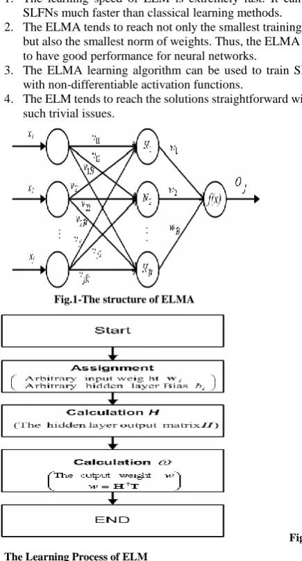
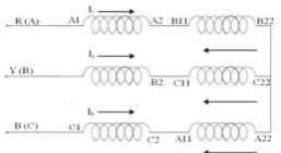
In the ELMA, the output weights are analytically computed [2, 24] by using the MP generalized inverse instead of iterative learning scheme. Fig.2 shows the learning procedure and struc-ture in ELMA. As shown in Fig.1, the ELM consists of sin-gle-hidden layer feed forward networks (SLFNs). The significant features of ELM can be summarized as follows:
1. The learning speed of ELM is extremely fast. It can train SLFNs much faster than classical learning methods.
2. The ELMA tends to reach not only the smallest training error but also the smallest norm of weights. Thus, the ELMA tends to have good performance for neural networks.
3. The ELMA learning algorithm can be used to train SLFNs with non-differentiable activation functions.
4. The ELM tends to reach the solutions straightforward without such trivial issues.
Fig.1-The structure of ELMA
[image:3.595.51.269.200.604.2]
Fig. 2- The Learning Process of ELM
3.2. Different Types of Stator Winding Connections
Three phase SCIM has six numbers of input terminals. So, it is possible to connect either star or delta connection mode with each phase energized two sets of turns in the stator winding. These two sets of turns can be connected either in series or parallel with the input supply, to cause variation of either star to delta or delta to star connection mode. These are the following different possibil-ities of stator winding connections are presented below as shown in figures 3 to 12.
4. SIMULATION RESULTS AND
DISCUS-SION
4.1 Conventional Design
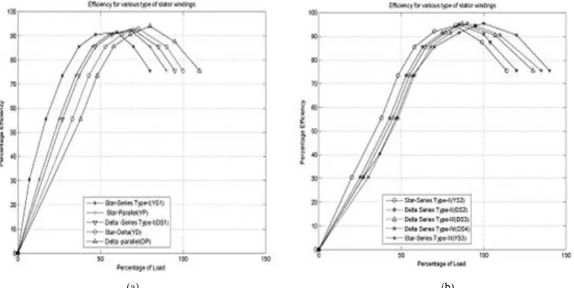
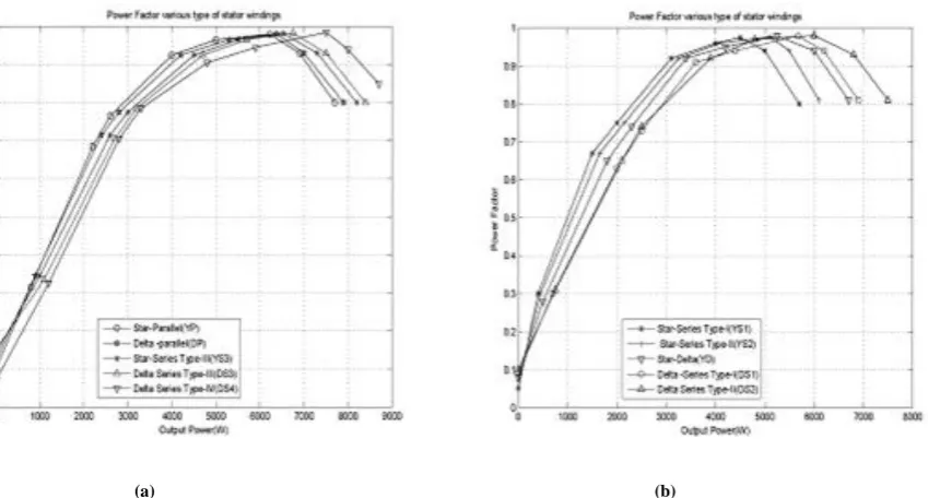
In Fig. 13. shows a conventional design of Efficiency as a function of percentage of load for various types of stator winding and Fig.14 represent a Power factor as a function of output power for various types of stator winding. The motor efficiency and power factor are considered stator winding connection modes. The intersection points are identified. The YS2 is connection was not considered in those zones because it does not contribute to the improvement of the resultant motor efficiency curve.
4.2.Optimal Design
Fig. 15 exhibits optimal design results for efficiency as a function of percentage of load for various types of stator winding and Fig.16 shows power factor as a fun ction of output power for various types of stator winding. In Table–1 a comparison for Normal Design and Optimal Design in made. The two different cases are considered in the three phase IM design:Case 1. The power loss effect is not included in the objective function, Case 2. The power loss effect is included in the objective function.
5.
CONCLUSION
A three-phase stator winding with two sets of turns is proposed. The described idea can be used in motors with wide load varia-tions and with long low load in service periods. ELMA-based design approach has been successufully applied to a 7.5-kW, 4-pole, multiflux SCIM, in order to improve the efficiency-load curves resulting from each possible connection mode. A software package that analyzes and optimizes the steady-sate performance of multiflux SCIMs has been developed. The presented simulated results demonstrate that the proposed method can lead to signiifcant improvements in the efficiency curves of multiflux SCIM, contributing to increase their benefits in terms of energy savings. Nevertheless, further studies are necessary to prove the accuracy and effectiveness of the presented approach, including the construnction and experimental test of an optimized multiflux SCIM prototype.
6. ACKNOWLEDGMENT
The authors wish to thank M/s RVS College of Engineering and Technology, Coimbatore for providing infrastructure facility to perfom the presented work.
[image:3.595.355.493.560.733.2]Fig. 3: Delta Parallel (DP) Connection.
Fig. 6: Delta-series type II (DS2) Connection.
Fig. 7: Delta-series type III (DS3) Connection.
Fig. 8: Delta-series type IV (DS4) Connection.
Fig. 9: Star Delta (YD) Connection.
[image:4.595.360.489.71.141.2]Fig. 10: Star-series type I (YS1) Connection.
[image:4.595.99.242.73.254.2]Fig. 11: Star-series type II (YS2) Connection.
TABLE.1
Comparison for normal design and optimal design.
Description
Normal design
Optimal design Case-1 Case-2 Full-Load Efficiency (%) 84.176 96.02 93.743 Full-Load Power Factor 0.8432 0.984 0.962 Maximum Stator
Tempera-ture Rise in C°
76.43 7
57.431 57.320
Maximum Rotor Tempera-ture Rise in C°
76.43 7
57.297. 57.341
Maximum to Full-Load
Torque ratio 2.735
3.023 2.952
Starting to Full-Load Torque
Ratio 1.52
1.83 1.73
Starting to Full-Load
Cur-rent Ratio 4.425
5.3 5.195
Length of Stator in m 0.563 0.5175 0.5262 Diameter of Stator in m 0.387 0.3583 0.3596 Outer Diameter of Stator in
m 0.448
0.5387 0.5398
Ratio L/ 1.342 1.682 1.5932
Stack Length to Pole Pitch
Ratio 1.325
- 1.7394
Stator Depth to Width ratio 4.055 - 34.923
Stator Core Depth in mm 4.239 - 119.987
Average Air gap Flux
Den-sity in wb / mm2 0.468
18200 18300
Stator Winding Current
Density in A/ mm2 4.57
3.243 3.193
Rotor Winding Current
Density in A/ mm2 7.76
4.362 4.273
Stator Iron Loss in watts 273.4 50
4.7327 4.6893
Rotor Copper Loss in watts 126.7 20
3.284 3.19984
Stator Copper Loss in watts 287.9 30
7.621 7.743
Ampere Conductors per
meter 18500
[image:4.595.306.530.183.596.2] [image:4.595.108.236.621.693.2]International Journal of Computer Applications (0975 – 8887) Volume 43– No.22, April 2012
[image:5.595.80.513.73.270.2](a) (b)
Fig. 13. Efficiency as a function of load for: (a) DP, YP, DS1, YD and YS1connections;(b) YS2, DS2, DS3, DS4 and YS3 connections.
[image:5.595.65.501.303.503.2](a) (b)
Fig. 14. Power factor as a function of load for: (a) YP,DP,YS3,DS3 and DS4 connections;(b) YS1,YS2,YD,DS1and DS2 connections.
(a) (b)
[image:5.595.60.473.536.743.2](a) (b)
Fig. 16. Power factor as a function of load for:(a)YS1,YS2,YD,DS1 and DS2 connections; (b)YP,DP,YS3,DS3 and DS4 connections.
6.
REFERENCES
[1] Andreas Binder and Keith Bradley. “Efficiency Deter-mination Methods - Economical Consequences and Application Rules”, 25.05.2005 University of Notting-ham School of Electrical and Electronic Engineering.
[2] Anibal T. de Almeida, Fernando J. T. E. Ferreira Joao Fong, and Paula Fonseca. “EUP Lot 11 Motors Final Report February 2008”, ISR- University of Coimbra.
[3] C. Kral, A. Haumer, and C. Grabner. “Consistent In-duction Motor Parameters for the Calculation of Partial Load Efficiencies”, Proceedings of the World Congress on Engineering 2009 Vol I WCE 2009, July 1 - 3, 2009, London, U.K.
[4] Fernando J. T. E. Ferreira, member, IEEE, and anibal T. de almeida, senior member of IEEE. “Novel Multiflux Level, Three-Phase, Squirrel-Cage Induction Motor for Efficiency and Power Factor Maximization” IEEE Transactions on energy conversion, Vol. 23, No. 1, march 2008.
[5] Giampaolo Liuzzi1, Stefano Lucidi, Veronica Piccialli1, Marco Villani. “Design of induction motors using a mixed-variable approach”, Computational Management Science © Springer-Verlag 20.
[6] Guang-Bin Huang and Chee-Kheong Siew “Extreme Learning Machine with Randomly Assigned Rbf Ker-nels” International Journal of Information Technology, vol. 11 no. 1.
[7] Guang-Bin Huang, Qin-Yu Zhu, Chee-Kheong Siew “Extreme Learning Machine Theory and Applications” Neurocomputing 70 (2006) 489–501.
[8] Guang-Bin Huang, Xiaojian Ding, Hongming Zhou, “Optimization Method Based Extreme Learning Ma-chine for Classification” Science Direct 10 May 2010.
[9] Guang-Bin Huang,Lei Chen, “Enhanced random search based incremental extreme learning machine ” 21 No-vember 2007.
[10]J. Siva Prakash and R. Rajesh “Random Iterative Ex-treme Learning Machine for Classification of Electronic Nose Data” International Journal of Wisdom Based Computing, vol. 1(3), December 2011.
[11]John S. Hsu, Senior Member, IEEE, John D. Kueck, Senior Member, IEEE, Mitchell Olszewski, Don A. Casada, Pedro J. Otaduy, and Leon M. Tolbert, Member, IEEE, “Comparison of Induction Motor Field Efficiency Evaluation Methods”, IEEE Transactions on Industry Applications,vol. 34, no. 1, January/February 1998.
[12]Kentli “A Survey on Design Optimization Studies of Induction motors during the last decade”, Journal of Electrical & Electronics Engineering Year-2009, vol.9, no.2, pp.969-975.
[13]Kristin P. Bennett, Emilio Parrado-Hernandez, “The Interplay of Optimization and Machine Learning Re-search”, Journal of Machine Learning Research 7 (2006) 1265–1281.
[14]Mark Van Heeswijk, Yoan Miche, Tiina Lindh-Knuutila, Peter A.J. Hilbers, Timo Honkela, Erkki Oja1, and Amaury Lendasse1., “Adaptive En-semble Models of Extreme Learning Machines for Time Series Prediction”, ICANN 2009, Part II, LNCS 5769, pp. 305–314, Springer-Verlag Berlin Heidelberg 2009.
[15]Mehdi Dhaoui, and Lassaad Sbita. “A New Method for Losses Minimization in IFOC Induction Motor Drives”, International Journal of Systems Control, Vol.1, Issue -2, 2010, pp. 93-99.
International Journal of Computer Applications (0975 – 8887) Volume 43– No.22, April 2012 Wseas Transactions on Circuits and Systems, ISSN:
1109-2734, Issue 8, Volume 8,pp 651-660, August 2009.
[17]Oleg Muravlev, Olga Muravleva, Eugenia Vekhter Tomsk Polytechnic University, Russia. “Energetic Pa-rameters of Induction Motors as the Basis of Energy Saving in a Variable Speed Drive”, Electrical Power Quality and Utilisation, Journal Vol. XI, no.2, 2005.
[18]Patricia D. Hough, Pamela J. Williams, “Modern Ma-chine Learning for Automatic Optimization Algorithm election” Computational Sciences and Mathematics Research Department. Sandia National Laboratories, California, USA, Aug. 2009.
[19]Piotr Gnacinski, Member, IEEE “Windings Temperature and Loss of Life of an Induction Machine under Voltage Unbalance Combined with Over- or Under Voltages”, IEEE Transactions on Energy Conversion, Vol. 23, No.2, pp 363-371, June 2008.
[20]Radha Thangaraj, Thanga Raj Chelliah, Pascal Bouvry, Millie Pant, and Ajith Abraham. “Optimal Design of Induction Motor for a Spinning Machine Using Popula-tion Based Metaheuristics”, 2010 InternaPopula-tional Confe-rence on Computer Information Systems and Industrial Management Applications.
[21]Ronnie Belmans, Wim Deprez Ozdemir Gol. “Increas-ing Induction Motor Drives Efficiency Understand“Increas-ing the Pitfalls”, Proceedings of Electro Technical Institute, Issue 223, pp 7-25, 2005.
[22]Subramanian Manoharan, Nanjundappan Devarajan, and Subbarayan M. Deivasahayam. “Review on Effi-ciency Improvement In Squirrel Cage Induction Motor by Using DCR Technology”, Journal of Electrical En-gineering, vol. 60, no.4, 2009, pp 227–236,
[23]V.P. Sakthivel, R. Bhuvaneswari and S. Subramanian, Senior Member, IEEE, “Adaptive Particle Swarm Op-timization for the Design of Three-Phase Induction
Motor Considering the Active Power Loss Effect”, In-ternational Journal of Computer and Electrical Engi-neering, Vol. 2, No. 4, pp. 627-636,August, 2010.
[24]Venugopal Chitra, K.S.Ravichandran, R.Varadarajan “Fuzzy Extreme Learning Machine Algorithm for Ma-trix Converter” International Journal of Reviews in computing 15th july 2011. Vol. 6.
7. AUTHORS PROFILE
S. S. Sivaraju took his B.E. degree in Electrical and Elec-tronics Engineering from Coimbatore Institute of Technolo-gy, Coimbatore in 1999 and later M.E degree in Electrical Machines from PSG College of Technology, Coimbatore in 2004. He is currently pursuing his doctoral work with Anna University Chennai in the area of Electrical Machines drives and controls. He has over 16 years of Industry and Teaching experience. He is currently working as an Assistant Professor, Department of Electrical & Electronics Engineering in RVS College of Engineering and Technology, Coimbatore, Ta-milnadu. He has published research papers in both National and international Conferences. He is a life member of ISTE, SSI.