Design of High Performance Multiplier Unit using
SDTBNS for DSP Applications
Subhashis Maitra
Electronics and Communication Engineering Department, Kalyani Government Engineering
College, Kalyani, Nadia, West Bengal, India
Amitabha Sinha
School of Information Technology, West Bengal University of Technology, Kolkata, West Bengal,
India
ABSTRACT
In this paper, a new number system “Single Digit Triple Base Number System (SDTBNS)” using 2, 3 and 5 as the bases have been introduced. Advantages of SDTBNS over Single Digit Double Base Number System (SDDBNS) have been discussed here. Dynamic range of the numbers represented in SDTBNS has also been dealt with in details. Analysis on complexity of the multiplication unit and execution time reveal the novelty of the proposed number system. Application of this number system in digital signal processing(DSP) has been explored and an efficient implementation of linear convolution has been presented.
Keywords
SDTBNS, SDDBNS , DSP, FIR Filter , DFT, DIT, Linear Convolution , FFT.
1.
INTRODUCTION
High performance, flexibility and low power consumptions are the most important issues in the current signal processing architectures. Signal processing algorithms are computationally intensive and therefore, the major issues are to enhance the speed of the multiplications and additions units. Double Based Number Systems (DBNS) [1][2][3]. In Double-Base number system, any integer can be represented as
1
.2 .3
m mn
i j m m
x
d
where
d
m
{1, 0}
andi
m,
j
m are integers. But this representation is highly redundant. If any representation contain minimum numbers of two integer terms , the representation is called canonic representation[4][5][6]. However to find the canonic DBNS representation of any integer is a difficult task. Hence the concept about near-canonic DBNS representation has been developed using greedy algorithm , where it has been proved that the maximum number of two- integer terms is equal to𝑂(log log xlog x )[1][7][8], where x is the integer to be converted to
DBNS. DBNS are becoming more attractive for their capabilities of performing multiplication operations efficiently. As double based number systems employ bases as 2 and 3, the indices ( [ i, j] pairs) to the bases 2 and 3 are used for addition and multiplication. Analysis of the recent literatures [1][9] indicates that how multiplication of two signed numbers can be performed in DBNS using only three adders, one look-up-table and one barrel shifter. However, there are certain limitations of DBNS[1][10]. To represent a wide range of numbers using DBNS, number of
bits of the indices need to be increased. This in turn increases the address space of LUT(Look-up-table) exponentially and leads to the increase in access time , hardware requirements and design complexities. These drawback can be eliminated using the proposed number system, a novel concept and is known as “Single Digit Triple Based Number Systems (SDTBNS)” in which bases used are 2,3 and 5. SDTBNS is an extension of TBNS (Triple Base Number System) [11] where the numbers can be represented using the following equation
Y= i,j,kdi,j,k2i3j5k (1)
For further enhancement of the performance of arithmetic operations and to reduce the hardware complexities, here we introduce SDTBNS, a modified version of SDDBNS [12][13][14]. Any number Y in SDTBNS is represented as Y=2i.3j.5k (2)
In TBNS and therefore, in SDTBNS one of the bases has been chosen as 5, since the decimal point shifting can be achieved easily only by adding or subtracting the indices of the bases 2 and 5. This cannot be achieved with other bases (like 7,11 etc.) and hence any number (integer and fraction) can be represented using the bases 2, 3 and 5 [such as 11,1.1and 0.11 can be represented as 230.3-27.57, 229.3-27.56 and 228.3-27.55 respectively]. Table 1 shows the representation of different integers in SDTBNS form and Table 2 shows the representation and accuracy level [in dB] of different numbers in both SDTBNS and SDDBNS. Considering the above advantages of SDTBNS, here an efficient implementation of popular DSP functions like linear convolution and DFT have been introduced .
2.
ALGORITHM TO CONVERT ANY
INTEGER
OR
FRACTION
INTO
SDTBNS
The algorithm to convert any number (integer or fraction) into its equivalent SDTBNS form is given below
Let Y=2i.3j.5k Step 1: Set a value of i, j and k so that 2i.3j.5k nearly equals to Y.
Step 2: For a fixed value of i (or j or k) change j and k by j and k , that is j to j+j and k to k-k or j to j-j and k to k+k ( or i and j by i and j or j and k by j and k) until the value of 2i.3j.5k falls into a given predefined accuracy.
Step 4: If accuracy does not matched , repeat step1 to step3, otherwise stop.
Note: Although different composite numbers can be expressed in SDTBNS form , different prime number can also be expressed in this form with lesser error than SDDBNS. For example to represent 7, the error in SDTBNS is 0.0005 whereas in SDDBNS, the error is 0.003. The representation of different prime number in SDTBNS, the corresponding error and the comparison with SDDBNS are shown in Table I.
3.
TBNS
ADDITION
AND
MULTIPLICATION
3.1 TBNS AdditionIf a and b are two integers represented in the form 2i.3j.5k and 2i+1.3j.5k, the results of addition will be 2i.3j+1.5k and this addition process obeys a definite rule
Ix(i,j,k)+Iy(i+1,j,k)=Iz(i,j+1,k) rule(1) This can be graphically shown using three dimensional TBNS map. Using the rule we can conclude about the solution of x+ y = z as (1,2,3),(2,4,6),(6,12,18) etc. where Ix(i,j,k) = x and Iy(i,j,k) = y and Iz(i,j,k) = z. That is x = 20.30.50, y = 21.30.50 and z = 20.31.50. Again addition of another two integer x and y, in the form Ix(i,j,k) and IY(i,j,k) yields the result as Iz(i+1,j,k) obeying rule (2).
Ix(i,j,k) +Ix(i,j,k) = Ix(i+1,j,k) rule(2)
Again if x and y are of the form 2i+1.3j.5k and 2i.3j+1.5k respectively, then z(2i.3j.5k+1) can be obtained from the equation
Iz(i,j,k+1) = Ix(i+1,j,k) + Iy(i,j+1,k) rule(3)
3.2
TBNS Multiplication
Let x and y be two integers represented in TBNS and their product will be z, where 2iz. 3jz. 5kz = 2ix+ iy. 3jx+ jy. 5kx+ ky,
here (ix, jx, kx), (iy, jy, ky) and (iz, jz, kz) are the indices of the bases 2, 3 and 5 of the three given integers respectively. It is clear that the multiplication process is simply a three dimensional shifts in TBNS map.
Let us consider the example of multiplication of two integers 12 and 45. The representation of 12 and 45 in SDTBNS, take the form as 12 = 22.31.50 and 45 = 20.32.51 and 12x45 = 22+0.31+2.50+1=22.33.51 and it obeys rule(4).
Iz(i+2,j+3,k+1)=Ix(i+2,j,k+3)+Iy(i+3,j,k+1) rule(4)
The above rules are for addition and multiplication in TBNS[10][11]. The rules are also applicable for the proposed SDTBNS.
Table 1
Different values of i , j and k to represent different integers in SDTBNS
Numbers 1st combination of i,j,k 2nd combination of i,j,k 3rd combination of i,j,k
i j k error i j k error i j k error
7 55 -30 -2 0.0005 -52 17 12 0.0007 38 32 -37 0.0005
11 30 -27 7 0.0005 -24 10 5 0.0013 29 0 -11 0.0049
13 80 -54 4 0.006 -43 28 1 0.003 34 5 -21 0.004
17 12 -18 5 0.084 -108 59 8 0.008 28 23 -26 0.041
19 48 -32 3 0.013 -128 60 16 0.008 301 -163 -23 0.006
23 37 -41 14 0.0005 -168 62 32 0.008 20 21 -21 0.0025
29 22 -24 9 0.005 -32 13 7 0.0005 41 6 -36 0.002
31 35 -38 13 0.049 -58 28 8 0.0038 38 8 -32 0.006
37 18 -11 2 0.005 -143 73 14 0.005 78 8 -50 0.005
4.
REPRESENTATION
OF
AN
INTEGER INTO SDTBNS FORM
In TBNS any integer can be represented as a sum of minimal number 3-integers (numbers of the form 2i.3j.5k ). But in SDTBNS, the same can be represented using only a Single Digit of the form 2i.3j.5k. For example, seven in SDTBNS, can be represented as 255.3-30.5-2, where error is –82.9 dB [20log(.0005/7)] Similarly the other integers can be represented in
SDTBNS form for different combination of the indices i, j and k as shown in Table 1. Table 1 gives an idea about how the errors in SDTBNS vary with the variation of the indices (i.e. i ,j and k) to the bases 2 , 3 and 5. The value of i, j and k can be minimized at the cost of accuracy. So an optimal value of i, j and k are to be taken in order to reduce errors and data bus width. For example 7 in SDTBNS can be represented as 7 = 255.3-30.5-2, 7 = 2-52.317.512 and 7 = 238.332.5-37. In the first case the error is 0.0005 and the maximum bus width to represent i, j and k is of 16-bit. In the second and the third cases the errors are 0.0007 and 0.0005 whereas the maximum bus width are of 18-bit and 21-bit respectively. So the first
case should be considered in order to get efficient result. Table 2 shows the optimal values of i, j and k to represent different number. From Table 2 it is clear that as the negative error in dB increases, the system performance will be increased. Infinite error in dB indicates no error. Figure 1 shows the error in dB for SDTBNS and SDDBNS. So it is also clear from Table 1 that to represent 5 in SDTBNS (5=20.30.51) and in SDDBNS (5=2-69.345), the maximum number of bits required for the exponents of the bases 2, 3, 5 in SDTBNS is two whereas in SDDBNS, it is seven. Similarly to represent other integer SDTBNS requires less number of bits for the exponents.
5.
ACCURACY
OF
SDTBNS
REPRESENTATION
Theorem 1: Any number can be expressed in SDTBNS form up to m or k decimal places with the same
[image:3.595.99.496.134.404.2]accuracy, where m or k are the exponents to the bases 2 and 5 respectively to represent an integer as 2m.3n.5k.
Table 2
Numbers represented in SDTBNS
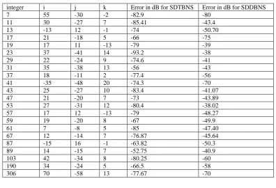
integer i j k Error in dB for SDTBNS Error in dB for SDDBNS
7 55 -30 -2 -82.9 -80
11 30 -27 7 -85.41 -43.4
13 -13 12 -1 -74 -50.70
17 21 -18 5 -66 -75
19 17 11 -13 -79 -39
23 37 -41 14 -93.2 -38
29 22 -24 9 -74.6 -41
31 35 -38 13 -56 -43
37 18 -11 2 -77.4 -56
41 -35 -48 20 -74.3 -70
43 25 -27 10 -83.4 -41.07
47 21 -20 7 -73 -43.89
53 27 -31 12 -80.4 -38.02
57 17 12 -13 -79 -48.27
59 19 -20 8 -67 -49.9
61 7 -8 5 -85 -47.40
67 12 -14 7 -76.87 -45.64
87 -15 16 -1 -63.82 -50.3
89 14 -15 7 -52.75 -40.9
103 42 -34 8 -80.25 -60
190 34 -24 5 -66.5 -58
306 70 -58 13 -77.67 -70
Proof: Let us assume that X = 2m. 3n. 5k
Now for k > m, let k = k1 + m, then
X = 2m. 3n. 5k1+ m = 10m. 3n. 5k1 (3)
Again for k < m, let m = m1 + k, then
X = 2m1+ k. 3n. 5k = 10k. 3n. 2m1 (4)
So from (3) and (4), it is clear that the value of X can be changed by diving it with 10 for m or k times and can be expressed with same accuracy.
Theorem 2: The accuracy can be increased if the ratio of the change of the exponents to the bases 2 and 5 can be made equal to q, where q may be an integer or fraction and known as accuracy factor.
Proof: Let us assume that any number X can be represented in SDTBNS form as X= 2m.3n.5k,
Let X changes by X due to the change of m to m, n to n and k to k
Hence, X+X = 2m+m.3n+n.5k+k [where X is the accuracy] =2m.3n.5k.2m.3n.5k = 2m.3n.5k. X
Now let 5k = .2m1.3n1. So X+X = .2m+m1.3n+n1.X Let 3n+n1 = 2m2.
Hence, X+X = ..2m+m1+m2.X
Now for X tends to 0, either . tends to one or m+m1+m2 tends to zero.
For .=1, (5k/2m1.3n1) . (3n.3n1/2m2 ) =1
or 5k.2-(m1+m2).3n = 1. Again let, 5 = .2q, where << 1,
So k. 2qk. 2- (m1+m2).3n = 1 and hence either qk - (m1+m2) = 0 or n = 0, since k << 1. So qk =m1+m2 =m.
6.
APPLICATIONS OF SDTBNS
6.1
To Find DFT of a Signal
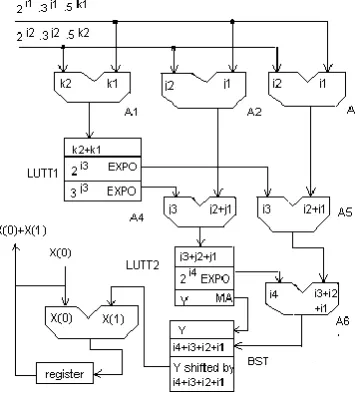
Here we will discuss how SDTBNS can be used to implement the linear convolution. The proposed architecture for SDTBNS is shown in Fig-2. Here, we have taken an example to compute the linear convolution of the signal x(n)={1,-1,1,0,0} using DFT in SDTBNS.
Suppose, h(n)={2,2,1,0,0}. Let us assume that the length of both the sequences is L = M = 3. (Where the
duration of x(n) and h(n) are L and M samples respectively) Therefore we add M – 1 = 2 zero samples to the sequence x(n) and L – 1 = 2 zero samples to h(n) so that the length of both the sequences is L+M-1 = 5. Here N = 5. Then the Fourier transform of the sequence x(n) is given by,
X(k) = x n e−
j2π nk
N = x(n)e− j2π nk
5 4
n=0 (N−1)
n=0 ,
that is, X(0)=1,
X(1) = 1-1(0.309-j0.951)+1(-0.809- j0.587) = - 0.118 + j0.364
X(2) = 1-1(-0.809-j0.587)+1(0.309 + j0.951) =2.118 + j1.5387
= 2.118 - j1.5387
X(4) = 1-1(0.309+j0.951)+1(-0.809 +j0.587)
[image:4.595.183.401.123.294.2]= -0.118 - j0.364
Figure 1. Different numbers vs. error represented in SDTBNS and SDDBNS.
Fig.2. SDTBNS Architecture
[image:4.595.177.355.336.534.2]In SDTBNS, the real and imaginary parts for different values of N have been shown in Table 3 whereas the real and imaginary parts of the corresponding X(n) are shown in Table 4.
Similarly values of H(n) for different values on n are, H(0) = 5
H(1) = 2(1)-2(0.309-j0.951)+1(-0.809- j0.587) = 1.809-j2.489
H(2) = 2(1)+2(-0.809-j0.587)+1(0.309 + j0.951) = 0.691-j0.223
H(3) = 2(1)+2(-0.809+j0.587)+1(0.309- j0.951) = 0.691+j0.223
H(4) = 2(1)-1(0.309+j0.951)+1(-0.809 +j0.587) = 1.809+j2.489
The real and imaginary parts for H(n)‟s in SDTBNS are given in Table 5.
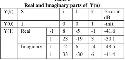
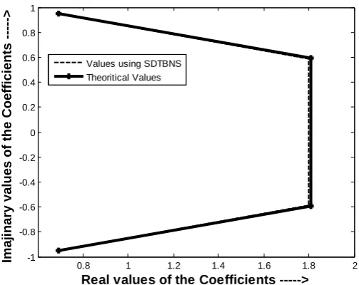
Again we know that, Y(k) = X(k)H(k). Hence the value of Y(k) and the corresponding errors in SDTBNS are given in the Table 6. From Fig.3, it is clear that the results using SDTBNS are accurate with the theoretical values.
Table 3
Real and Imaginary parts of different values of N
No. i j k Error in dB
0.309 -37 34 -8 -49.8
0.587 8 -7 1 -59.8
0.809 31 -30 7 -44
0.951 -17 18 -5 -46
5 10 15 20 25 30 35 40 45
-100 -90 -80 -70 -60 -50 -40 -30
Different Integers ---->
E
rr
o
r
--->
[image:4.595.318.542.706.769.2]Table 4
Real and Imaginary parts of X(n)
No. i j k Error in dB
0.118 8 -7 0 -42
0.364 33 -32 7 -45
2.118 42 -39 9 -72.5
1.5387 52 -50 12 -48
Table 5
Real and Imaginary parts of H(n)
No. I j k Error in dB
0.223 25 -23 4 -46.9
1.809 0 2 -1 -46
0.691 -44 45 -12 -44.7
2.489 -10 13 -4 -61.9
6.2
To Find FFT of a Signal using DIT
Algorithm
Let us assume that the DFT of the sequence x(n) = {1,2,3,4,4,3,2,1} are to be found out using DIT (Decimation-in-time) Algorithm. The twiddle factor associated with the flow graph are supposed to be W08 = 1; W18= 0.707 - j0.707; W
2
8= -j and W 3
8 = - 0.707 - j0.70. Now if x(n) = {1,2,3,4,4,3,2,1}, the inputs to the first stage will be selected from the LUT as x(0) =1, x(1) = 4, x(2) = 3, x(3) = 2, x(4) = 2, x(5) = 3, x(6) = 4 and x(7) = 1. The outputs of the first stage are x‟(0 = x(0) + x(1) W08, x‟(1) = x(0) - x(1) W0
8, x‟(2) = x(2) + x(3) W08, x‟(3) = x(2) - x(3)W08, x‟(4) = x(4) + x(5)W08, x‟(5) = x(4) - x(5)W08, x‟(6) = x(6) + x(7)W0
8 and x‟(7) = x(6) - x(7)W0
8. Where x(1)W08 = 1x1 = 20.30.50.20.30.50 = 20.30.50 can be found out from the BST(Barrel Shifter) which is then added with x(0) in A7 of the first SDTBNS unit in the first stage. There are eight such units and each alternate units has an inverter at their input for subtraction. The architecture is shown in Figure 7. The output of the second stage are x”(0) = x‟(0) + x‟(2) W0
8, x”(2) = x‟(0) - x‟(2) W08 , x”(1) = x‟(1) + x‟(3) W28, x”(3) = x‟(1) - x‟(3) W28, x”(4) = x‟(4) + x‟(6) W08, x”(6) = x‟(4) - x‟(6) W0
8, x”(5) = x‟(5) + x‟(7) W28 and x”(7) = x‟(5) – x‟(7) W2
8. Now for the case x”(0) = x‟(0) + x‟(3)W0
8 = 5 + 5x1 = 5+20.30.51x20.30.50 = 10 which can be obtained from A7 of the first SDTBNS unit in the second stage. The final output are x”‟(0) = x”(0) + x”(4) W08, x”‟(4) = x”(0) – x”(4) W08 , x”‟(1) = x”(1) + x”(5) W18, x”‟(5) = x”(1) - x”(5) W18, x”‟(2) = x”(2) + x”(6) W28, x”‟(2) = x”(2) - x”(6) W28, x”‟(3) = x”(3) + x”(7)W3
8 and x”‟(7) = x”(3) - x”(7)W 3
8. Now x”‟(0) = x”(0) + x‟(4)W08 x”‟(0) = 10 +10x1 = 10 + 21
.30.51x20.30.50 = 20 which can be obtained from A7 of the final SDTBNS unit after third clock pulse. Similarly the other output can be obtained from the final adder of the individual SDTBNS unit.
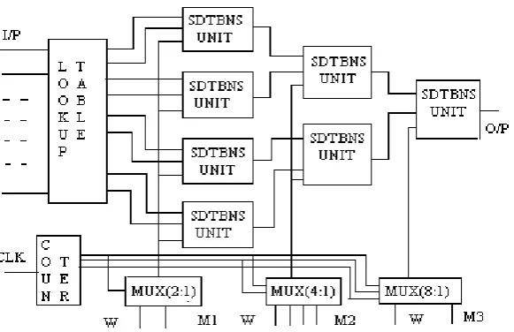
As shown in Fig. 7, there is only one counter. For the 1st clock pulse, the multiplexers are set to select the twiddle factor W08 = 1. At the same time the sequences x(0) = 1, x(1)=4 , …… x(7) = 4 will be selected from the look-up-table. Here the look-up-table converts the input sequence to the sequence {1, 4, 3, 2, 2, 3, 4, 1}. Now x(0), x(1) and W08 will be fed to the input of the SDTBNS unit which gives the value x‟(0) = x(0) + x(1) W08 = 1+4x1 = 5. The output of the second SDTBNS unit is x‟(2) = x(2) + x(3) W0
8 = 3+2x1 = 5. Similarly the outputs from the other two SDTBNS units are x‟(4) = 5 and x‟(6) =5. For the 2nd
pulse, the counter gives „001‟ which select W08= 1 from M2. The first MRNS (Mixed Radix Number System) unit of the second layer then gives the output as x”(0) = x‟(0) + x‟(2)W0
8 = 5+5x1= 10. The output of the 2nd SDTBNS unit of the second layer is x”(4) = x‟(4) + x‟(6)W0
8 = 5+5x1 = 10. At the 3rd pulse the counter C3 gives „010‟ which selects W0
8 = 1 from M3. The output of the SDTBNS unit of the third layer is x”‟(0) = x”(0) + x”(4) W0
8 = 10+10 = 20. For the 2nd pulse, -W0
8 = -1 is selected from M1 and the output of the four SDTBNS unit in the first layer are x‟(1)=x(0) - x(1) W08 , x‟(3) = x(2) - x(3) W08, x‟(5) = x(4) - x(5) W08 and x‟(7) = x(6) - x(7) W08 respectively whereas the output from the SDTBNS unit in the second layer are then x”(0) and x”(4). Now for the 3rd
pulse W28 = -j is selected from M2 and the output of the SDTBNS unit in the second layer are x”(1) = x‟(1) + x‟(3) W2
8 and x”(5) = x‟(5) + x‟(7) W28 respectively and at the same time the output of the SDTBNS unit in the third layer is x”‟(0) = 20. The output from the SDTBNS units in the first layer at the 3rd pulse are x‟(0) = x(0) + x(1) W0
8, x‟(2) = x(2) + x(3) W 0
8, x‟(4) = x(4) + x(5) W08 and x‟(6) = x(6) + x(7)W08 respectively. At the 4th pulse the output of the first layer are x‟(1) = x(0) - x(1) W0
8, x‟(3) = x(2) - x(3)W08, x‟(5) = x(4) - x(5) W0
8 and x‟(7) = x(6) - x(7) W0
8 respectively, the output of the second layer x”(2) = x‟(0) - x‟(2) W0
8 and x”(6) = x‟(4) – x‟(6)W08 respectively (since - W08 = -1 is selected from M2 for „11‟) and the output of the third layer is x”‟(1) = x”(1) + x”(5) W1
[image:5.595.321.537.530.633.2]8 (since W18 = 0.707 –j0.707 is selected at the 4th pulse). Thus we get the output sequences as {20, -5.828- j2.414, 0, - 0.172 - j0.414, 0, - 0.172+j0.414, 0, -5.828+j2.414}. At the time when W18 = 0.707 –j0.707 is selected, the operation to be performed is at first x1”‟(1) = 0.707. x”(5) +x”(1) and then x2”‟(1) = 0.0 – 0.707.x”(5), where x”‟(1) = x1”‟(1) + j x2”‟(1).
Table 6
Real and Imaginary parts of Y(n)
Y(k) S i J k Error in
dB
Y(0) 1 0 0 1 -infi
Fig.-3. SDTBNS vs. Theoretical results.
7.
DYNAMIC RANGE
The range of representation of different integers in SDTBNS is much more than that in SDDBNS representation. For example, in SDTBNS representation using only one bit (i.e. the indices is either 0 or 1), the maximum number of integers that can be represented without any error is eight(1,2,3,5,6,10,15,30) and that with error is 22(30-8), whereas in SDDBNS, the maximum number of integers that can be represented without any error is only four(1,2,3,6) and with error is 2(6-4). Similarly for two bit, the range (without any error) in SDTBNS and SDDBNS are 22x22x22 = 64 and 22x22 = 16 respectively and with error are 22x32x52 - 22x22x22 = 900- 64 = 836 and 22x32 - 22x22 = 36 – 16 = 20 respectively. So if we use SDDBNS, the requirement of hardware needed for arithmetic operation is approximately four times greater than that if we use SDTBNS, to cover the same range, otherwise the execution time will be more than that for SDTBNS. To increase the dynamic range
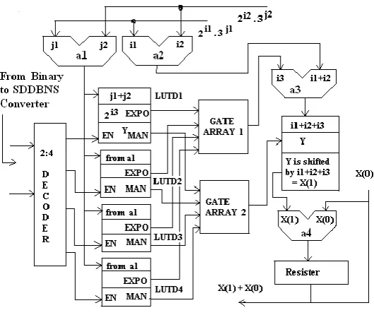
in case of SDDBNS, the requirements of hardware are to be increased as shown in Fig.6.The figure shows that we have to use a decoder to enable which look-up-table has to be used for a specified range. We have to use two gate array to input the ALU (a3) and the BS (Barrel Shifter) from the corresponding look-up-table, while the other look-up-tables remain disabled . The input to the Decoder comes from the SDDBNS converter. In general for N-bit, the range of number that can be represented in SDTBNS is 2N greater than that in SDDBNS.
8.
SIZE OF DIFFERENT HARDWARE
The size of the lookup table, barrel shifter and other hardware components can be reduced to a great extent if we use SDTBNS in place of SDDBNS. This can be understood from the following example considering the Fig.2.and Fig.7. Here it is supposed that two numbers (both are 7) are to be multiplied. Now 7 is equivalent to 255.3-30.5-2 in SDTBNS and 2109.3-67 in SDDBNS. In case of multiplication using SDTBNS, the sum of the indices to the bases 2, 3 and 5 will be 110, -60 and -4 respectively and using SDDBNS, the sum of the indices to the bases 2 and 3 will be 218 and -134 respectively. Hence maximum 7-bit, 6-bit and 3-bit respectively are required to represent 55, 30 and 2(including sign bit). Again to represent
109 and 67, maximum 8 bits (including sign bit) are required. So the size of the ALU (A3,A2 and A1) for SDTBNS and ALU (a2 and a1) for SDDBNS will be of 8 and 9 bit wide respectively. The data bus length for the results from the ALUs in SDTBNS and SDDBNS will be of maximum 8 and 9 bit respectively. Now 5-4 = 2276.3-180. Again to represent 180, 9 bits are required and hence the size of the ALU (A4) will be of maximum 9-bit wide and the data bus length from A4 will be of 9-bit since the output from A4 (–240) needs maximum 9-bits (including sign bit). Now the indices to the base 3 in a1[lower case for adder in SDDBNS] is -134. So the size of LUTD1 used for SDDBNS multiplication is of 134 address space. Again the indices to base 5 in A3 is -4 and hence the size of LUTT1 used in SDTBNS multiplication is of 4 address space. The output from LUTD1 and LUTT1 are 3x2-264(3 -134
) and 2276.3-180 respectively. The size of a3 will be of maximum 10-bits wide and that of the BSD will be of 30-bits wide [to shift the mantissa either right or left by 14 times, 28-bits (-46 (MOD32) = -14) are required and 2-28-bits for representing 3]. A5 will be of maximum10-bits wide (110 needs 8-bits and 276 needs 10-bits) wide. The output of A4 is –240. Hence the address space of LUTT2 will be 240. Now
3 -240
= 3x2-382. The input to A6 are –382 and 386 and hence the size of A6 is 9-bit wide. The output of A6 is 4. Again to represent 3, 2-bits are required and to shift 3 (either right or left) by 4 times, 8 –bits are required. Hence the size of the BST is of 10-bit wide as mentioned in Table 7. This table is true only in the case of multiplication of 7 with 7. For higher range, all the different parameters expressed in Table 7, will be increased further if SDDBNS is used. So it is clear from Table 7 and from the above discussion that, if we use SDTBNS in place of SDDBNS, we will get advantages w.r.to the hardware requirement and bus length. Table 8 gives an idea how the sizes and the requirements of hardware component increases with the ranges ( considering the ranges as 1-25,26-50,51-75, 76-100). Fig.7 shows that in SDDBNS, four LUT are to be used to cover the whole range that can be done with a single LUT in SDTBNS. Though a single look-up-table can also be used in SDDBNS, but in that case the address space of that LUT will be excessively high and hence access time will be more. Also the design of LUT in SDDBNS is much more complex. Fig. 4. and Fig.5. give an idea about how SDTBNS are more attractive than SDDBNS .
0.8 1 1.2 1.4 1.6 1.8 2
-1 -0.8 -0.6 -0.4 -0.2 0 0.2 0.4 0.6 0.8 1
Real values of the Coefficients --->
Imaj
inary
values
of t
he Coef
fici
ents
--->
9.
TIMING COMPLEXITY
Considering Fig.6 and Fig 7, it can be understood that how the execution time can be reduced using SDTBNS. Let us assume that, TD = delay in decoder used in SDDBNS architecture, TA = delay in the ALU used for SDTBNS and SDDBNS (it is assumed that the processing speed for addition in the ALU used for both SDDBNS and SDTBNS are same).
Since the address spaces for the LUTT used for SDTBNS are of maximum 176 (as shown in Table 8) and that for SDDBNS are of maximum 1390, so TLT ( Delay in the look-up-table used in SDTBNS ) < TLD(Delay in the look-up-table used in SDDBNS).
TG = delay in gate array used in SDDBNS .
Since the size of the barrel shifter used in SDTBNS is of maximum 10 bits length and that used in SDDBNS is of maximum 30 bits length, TBST ( Delay in the barrel shifter used in SDTBNS) < TBSD ( Delay in the barrel shifter used in SDDBNS). Then total execution time in SDDBNS is
TSDDBNS= TA(for a1 or a2)+ TD + TLD + 2TG + TA (for a3) + TBSD +TA (for a4) and that in SDTBNS,
TSDTBNS = TA ( for A1 or A2 or A3)+ TLT ( for LUTT1) + TA (for A4 or A5) + TLT (For LUTT2) + TA (for A6) + TBSD + TA (for A7).
Now since TLT < TLD and TBST < TBSD and since TG is multiplied by two , hence TSDTBNS < TSDDBNS.
10.
SDTBNS REDUCTION RULES
We can use a geometrical interpretation for each of the bases(2, 3 and 5) to represent any integer in SDTBNS. Non-zero SDTBNS digits are represented as black squares. This interpretation helps us to demonstrate simple identities on special combination of the black cells. For example 21.30.50 +20.31.50 = 20.30.51. In general 2i+1.3j.5k + 2i.3j+1.5k = 2i.3j.5k+1. Figure 8 (a) and (b) show the two integers 21.30.50 and 20.31.50 represented in SDTBNS form and Figure 8(c) shows the result.
11.
ADDITION
OF
TWO
SDTBNS
NUMBERS
Suppose a and b are two integers that can be represented in SDTBNS as 2i1.3j1.5k1 and 2i2.3j2.5k2. Then the result of addition of a and b will be
c = a +b = 2i1. 3j1. 5k1+ 2i2. 3j2. 5k2
= 2i2. 3j2. 5k2 [1+ 2i1. 3j1. 5k1/ 2i2. 3j2. 5k2]
= 2i2. 3j2. 5k2 [1+ 2i1. 3j1. 5k1. 2−i2. 3−j2. 5−k2]
= 2i2. 3j2. 5k2[ 1 + A] = 2i2. 3j2. 5k2. A1
Now A can be found out using the proposed SDTBNS unit. The output of the barrel shifter of the SDTBNS unit is then added with binary one in the adder unit A8 and the output is A1. A1 is then multiplied in the same SDTBNS unit whose output gives the result of a + b.
12.
ACCURACY OF SDTBNS OVER
SDDBNS
The accuracy to represent different numbers in SDTBNS shows its advantage over SDDBNS. Table.1.depicts the representation of different numbers
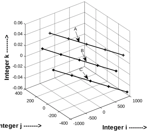
for different values of i, j and k and also represents the error in dB. Figure 9(a) and (b) represent the accuracy level of different numbers using different combination of i, j and k in dB and in percentage. From the figures it is clear that curve C gives better accuracy over A and B. Figure 10 represents how the accuracy of SDTBNS, depends on the values of i and k. For the curve A accuracy changes from 0.0147 to -0.015 and in each step the corresponding accuracy will be the previous accuracy(p.a.) – 0.0063. The change in the values of i and k are from -623.0 to 733.0 and from 290.0 to -294.0 respectively and steps for the changes of i and k are 339 and 146 respectively. Hence m = 339 and k = 146 and q = m/k = 2.32. For curve B and C, corresponding accuracies changes from -0.0524 to -0.0234 in step of (p.a. - 0.0073) and 0.0445 to 0.0153 in step of (p.a. – 0.0073 ) respectively. For both cases, „q‟ remains same. The term „q‟ is known as „accuracy factor‟ and it is mentioned in Theorem 2 that it varies with the exponents of the bases 2 and 3.
Figure 4. Hardware requirements for SDTBNS and SDDBNS.
1 1.5 2 2.5 3 3.5 4
5 10 15 20 25 30 35
Different Ranges of Number---->
Hardware
Requirem
ent i
n SDTBN
S and
SDDBNS
Figure 5. Hardware complexities for SDTBNS and. SDDBNS.
Figure 6. Architecture of SDDBNS used to cover the whole range that can be represented in SDTBNS.
1 1.5 2 2.5 3 3.5 4
200 400 600 800 1000 1200 1400 1600
Different Ranges of Number--->
Hardware
Comple
xiti
es i
n SDTBN
S and
SDDBNS
[image:8.595.163.428.367.590.2]Fig.7. Architecture to find out DFT using DIT Algorithm.
Fig.8(a). 21.30.50 represented in SDTBNS (b). 20.31.50 represented in SDTBNS (c) ) 20.30.51 represented in SDTBNS map.
Figure 9. Accuracy of representation of different number using SDTBNS (a) in dB and (b) in percentage.
5 10 15 20 25 30 35 40
-100 -50 0 50
Numbers ---->
Error in
dB
---->
Figure 9(a)
5 10 15 20 25 30 35 40
-40 -20 0 20
numbers---->
Error in
percenta
ge---->
Figure 9(b)
A
B C
A
B
[image:9.595.67.540.328.474.2]Figure 10. Variation of accuracy with respect to the variation of i and k.
Table 7
Size of ALU and Address Space for LUT used in SDTBNS and SDDBNS
No. System ALU size Address space of LUT Size of BS Maximum
length Address Bus
Maximum length of data bus
SDDBNS a1,a2 are 9-bit wide and a3 is 10-bit wide.
Address spaces for LUTD1 is 134.
30-bit 8-bit 10-bit
SDTBNS A1,A2,A3 are 8-bit wide , A4 , A6 are 9-bit wide,A5 is 10-bit wide.
Address spaces for LUTT1 and LUTT2 are 4 and 240 respectively
[image:10.595.52.542.376.469.2] [image:10.595.58.540.503.617.2]10-bit 8-bit 10-bit
Table 8
Size of different Hardware required in SDTBNS and SDDBNS
No system
range No. of ALU
ALU size(max)
No. of LUT
LUT size No. of
Decoder used
Gate array
SDDBNS 1-25 3 12-bit 2 852 address space One 2:1 12 ,2-input OR Gate
26-50 3 13 bit 4 1390 address space One 4:1 13 ,4-input OR Gate 51-75 3 13 bit 8 1300 address space One 8:1 13 ,8-input OR Gate 76-100 3 13 bit 16 1388 address space One 16:1 13, 16 input OR Gate SDTBNS 1-25 6 9 bit 2 Maximum 144 address space No decoder No gate array
26-50 6 10 bit 2 Maximum 144 address space No decoder No gate array 51-75 6 9 bit 2 Maximum 176 address space No decoder No gate array 76-100 6 10 bit 2 Maximum 132 address space No decoder No gate array
13.
CONCLUSIONS
Here a new concept to represent any integer in SDTBNS form has been illustrated and also a comparative study with SDDBNS has been discussed. From this illustration, ideas about the advantages of SDTBNS w.r.to SDDBNS in terms of bit efficiency, hardware complexity and speed have been dealt clearly. Using the concept of the proposed method, we have shown the implementation of linear convolution and DFT. The experimental results clearly indicate the high level accuracy in implementing DSP functions using the proposed number systems. The performance analysis of the DSP algorithms implemented using SDTBNS also indicates its novelty. Here We have also shown the optimal value of the
indices i, j and k to represent any number within a specified accuracy.
14.
REFERENCES
[1] Vassil S Dimitrov, Graham A. Jullien, Senior Member, IEEE, and William C. Miller, Senior Member, IEEE ,Theory and Application of the Double- Base Number System, IEEE Transaction on Computers, Vol. 48, No.10,Oct. 1999.
[2] P. Kornerup, “Comp. Arithmetic: Exploiting Redundancy in No. Representations,” Proc. ASAP ‟95, Strasbourg, France .
-1000 -500
0
500 1000
-400 -200 0 200 400 -0.06 -0.04 -0.02 0 0.02 0.04 0.06
Integer i --->
Integer j --->
Intege
r k
--->
A
B
[3] A. Avizienis, “Signed-digit Number Representation for Fast Parallel Arithmetic”, IRE Trans. Electronic Computer
[4] V.S. Dimitrov, G.A. Jullien and W.C. Miller, “An Algorithm for Modular Exponentiation”, Information Processing Letters, vol.66, no. 3, pp. 155-159, 1998.
[5] T. N. Shorey and R. Tijdeman, “Exponential Diophantine Equations, Cambridge University Press,1986.
[6] S. S. Pillai, “On the equation 2a - 2b = 3c – 3d ”, Bulletin of the Calcutta Math. Soc., vol. 37, pp. 15- 20, 1945. [7] V. Dimitrov and T.V.Cooklev, “Two algorithm for
modular exponentiation based on nonstandard arithmetic”, IEICE Transactions on Fundamentals of Electronics, Communications and Computer Science, vol. E78-A, no. 1, pp. 82 -87, Jan. 1995, special issue on cryptography and information security.
[8] J. A. Solinas, “Low-weight binary representations for pairs of integers”, Center for Applied Cryptographic Research, University of Waterloo, Waterloo, ON, Canada, Research Report CORR 2001-41, 2001. [9] J. Adikari, V. Dimitrov and L. Imbert, “Hybrid
Binary-Ternary Joint Sparse Form and its Application in Elliptic
Curve Cryptography”, Draft, July 2, 2008, supported by the Natural Science and Engineering Research Council of Canada.
[10] D.Hankerson, A.Menezes and S.Vanstone, Guide to Elliptic Curve Cryptography, Springer, 2004.
[11] Pavel Sinha, Amitabha Sinha, Krishanu Mukherjee and Kenneth Alan Newton, “Triple Base Number Digital and Numerical Processing System”, Patent filed under E. S. P. Microdesign Inc., Pennsylvania, U.S.A., U. S. Pat. App. No. 11/488, 138.
[12] S. Sadeghi-Emamchaie,G. A. Jullien, V.S. Dimitrov and W.C. Miller, “Digital Arithmetic using analog Arrays”, Proc., Eighth Great Lakes Symp. on VLSI, pp. 202-207, L. L., Feb.98.
[13] S. Maitra, A. Sinha, “A Single Digit Tripple Base Number System – A New Concept for Implementing High Performance Multiplier Unit for DSP Aplications”, Proceedings of the sixth International Conference on Information, Communication and Signal Processing(ICICS2007), December, 10-13,2007. [14] S. Maitra, A. Sinha, “Architecture of Mixed Radix
Number System –A New Approach of Designing Digital Filter”, proceedings of the 10th