Unicaste Routing Protocols in Mobile Ad Hoc Networks:
A Survey
Vivek Sharma
Amity School of Engg. & Tech. Bijwasan, New Delhi ,India
Bashir Alam
Phd, Jamia Milia Islamia University New Delhi, India
ABSTRACT
Mobile Ad hoc-networks (MANETs) are becoming increasingly important in today’s world. An important and essential issue for mobile ad hoc networks is routing protocol design. A major technical challenge in routing is due to the mobility of nodes in the network. During the last decade, active research work resulted in a variety of proposals. Routing protocols can be classified via the type of caste property, whether they are unicaste, multicast and broadcast. Further, ad-hoc unicaste routing protocols are classified into three categories: table driven, on-demand and hybrid. We filtered the total studies and reviewed various research papers published between 1998 and 2012. This paper presents a review and discusses 19 unicaste routing protocols designed for mobile ad hoc networks belonging to each category. Further advantages and disadvantages of each protocol are discussed.
General Terms
Mobile Ad-hoc networks, Routing Protocol,
Keywords
Unicast routing protocol, On-demand, active, reactive and hybrid protocols.
1.
INTRODUCTION
The Recent Research and survey shows that demand of wireless portable devices such as mobile phones, laptops and PDAs is increasing in everyday life. It leads to the possibility of spontaneous or ad hoc wireless communication. Two variations of mobile wireless network are: infrastructure network and infrastructure less network .Infrastructure network has bridges, known as base stations [1].These networks communicate with the nearest base station which lies within the range. Other variation is infrastructures less, which are also called as Mobile ad hoc network (MANET)[2].A MANET is a self-organizing collection of wireless mobile nodes that form a temporary network without the aid of a fixed networking infrastructure or centralized administration. In it each node can move freely and topology keeps on changing. Mobile nodes that are within each other’s radio range communicate directly via wireless links, while those that are far apart, rely on the other nodes to relay messages i.e. act as a router[1].
Two main features of MANET are low cost since no base stations or fixed infrastructure is required and convenience which makes it an excellent tool to handle the situations like disaster recovery, crowd control, search and rescue operation, and automated battlefields, etc. The behaviour of nodes in MANET is not unique, due to arbitrarily mobility, changes in topology, limited bandwidth, traffic density, hidden and exposed terminal node problem etc. Thus, routing in MANET
[3], [4], [5] becomes extremely challenging. A lot of innovative protocols have been introduced to get the best performance and the performance of each routing protocol differs in different environment. Thus, no single protocol is suitable for all the conditions.
This paper reviews the key studies of nineteen unicaste Mobile ad hoc routing protocols introduced by various authors. First we introduce classification of unicaste routing protocols based on the route discovery and routing information update mechanisms. Then we discuss the mobile ad hoc routing protocols routing mechanism. Further on, we discuss their advantages and disadvantages so that their behavior and performance can be captured under different circumstances.
2.
CLASSIFICATION OF ROUTING
PROTOCOLS
In wireless networks various parameters such as dynamism of the network, the impacts from transmission power, receiver sensitivity, noise, fading and interference, high error rate, power restrictions and bandwidth limitations[6] lead to active research work for mobile ad hoc networks. A lot of mobile ad hoc network routing protocols have been proposed in the last four decade. These protocols can be can be classified into three main categories [7]: proactive (or table driven), reactive (or on-demand driven) and hybrid on the basis of route discovery and routing information update mechanisms.
2.1
Proactive protocols
In proactive routing protocols [8], [9], [10], [11], the routes to all the destinations (or parts of the network) are determined at the start up, and maintained by using a periodic route update process. In proactive routing protocol each node maintains the information about the other nodes in the form of a table. The various proactive routing protocols differ in the way in which they update the routing information in the tables.
2.2
Reactive Protocols
2.3
Hybrid Protocols
When a network is large, the nodes are usually organized into a hierarchy.Hybrid routing protocols [5] attempts to combine the best features of proactive and reactive algorithms. It often consists of the two classical routing protocols: proactive and reactive. Hybrid protocols divide the network into areas called zones which could be overlapping or non-overlapping depending on the zone creation and management algorithm employed by a particular hybrid protocol. The proactive routing protocol operates inside the zones, and is responsible for establishing and maintaining routes to the destinations located within the zones. On the other hand, the reactive protocol is responsible for establishing and maintaining routes to destinations that are located outside the zones.
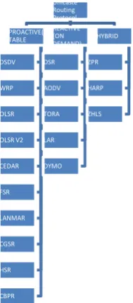
Fig.1. Classification of unicaste routing protocols for mobile ad hoc networks
2.1 Proactive protocols
2.1.1
DSDV
The Destination Sequence Distance Vector (DSDV) [12] is a table driven mobile ad hoc network routing protocol. DSDV is based on the improved Bellman-Ford algorithm where each node maintains a table that contains the shortest distance and the first node on the shortest path to every other node in the network. It incorporates table updates with the increasing sequence number tags to prevent loops, count to infinity problem and for faster convergence.
In routing tables of DSDV, an entry stores the next hop towards a destination, the cost metric for the routing path to the destination and a destination sequence number that is created by the destination. Sequence numbers are used in DSDV to distinguish stale routes from fresh ones and avoid formation of route loops. The route updates of DSDV can be either time-driven or event-driven. Every node periodically transmits updates including its routing information to its immediate neighbors. The tables are also forwarded if a node observes a significant change in local topology of the network. There are two ways of sending routing table updates in DSDV. One is full dump and another is incremental type, [12]. An incremental update takes a single network data
packet unit while full dump update may take multiple network data packets. An incremental update contains only those entries whose metrics have been changed since the last update is sent. Additionally, the incremental update fits in one packet.
Advantages and Disadvantages
Less delay is involved in the route set up process and existing wired network can be applied to ad hoc wireless networks with much fewer modifications. During the high mobility of nodes there is a heavy overhead control and therefore not scalable in ad hoc wireless network which has limited bandwidth and is highly dynamic [12]. Another disadvantage is that in order to obtain information about a particular destination node, a node has to wait for a table message initiated by the same destination node.
2.1.2 WRP
The Wireless Routing Protocol (WRP) is a proactive unicaste routing protocol for mobile ad hoc networks [13]. WRP inherits the properties of improved Bellman-Ford Distance Vector routing algorithm. To adapt to the dynamic features of mobile ad hoc networks, some mechanisms are introduced to ensure the reliable exchange of update messages and reduces route loops.
Each mobile node that uses WRP maintains a distance table , a routing table, a link-cost table and a Message Retransmission List (MRL)[7]. An entry in the routing table contains the distance to a destination node, the predecessor and the successor along the paths to the destination, and a tag to identify its state, i.e., is it a simple path, a loop or invalid. Storing predecessor and successor in the routing table helps to detect routing loops and avoid count-to-infinity problem, which is the main shortcoming of the original distance vector routing algorithm. A mobile node creates an entry for each neighbor in its link-cost table. The entry contains cost of the link connecting to the neighbor, and the number of timeouts since an error-free message was received from that neighbor.
In WRP, mobile nodes exchange routing tables with their neighbors using update messages. The update messages can be sent either periodically or whenever link state changes happen. The MRL contains information about which neighbor has not acknowledged an update message. If needed, the update message will be retransmitted to the neighbor. Additionally, if there is no change in its routing table since last update, a node is required to send a Hello message to ensure connectivity. On receiving an update message, the node modifies its distance table and looks for better routing paths according to the updated information.
In WRP, a node checks the consistency of its neighbors after detecting any link change. A consistency check helps to eliminate loops and speed up convergence. One shortcoming of WRP is that it needs large memory storage and computing resource to maintain several tables. Moreover, as a proactive routing protocol, it has a limited scalability and is not suitable for large mobile ad hoc networks.
Advantages and Disadvantages
WRP has same advantages as that of DSDV. In addition, it has faster convergence and involves fewer updates. Disadvantage of this protocol is that it requires larger memory and greater processing power from nodes in wireless ad hoc Unicaste
Routing Protocol PROACTIVE( TABLE DRIVEN) DSDV WRP OLSR OLSR V2 CEDAR FSR LANMAR CGSR HSR CBPR
REACTIVE (ON DEMAND) DSR AODV TORA LAR DYMO
[image:2.595.120.215.245.460.2]network [7]. It is not suitable for highly dynamic and for very large ad hoc wireless network.
2.1.3
OLSR
The Optimized Link State Routing protocol (OLSR)[14],[15],[16] is a proactive Link State routing approach. In the original Link State algorithm, each node propagates its link state information to all other nodes in the network.
In OLSR, every node transmits its neighbor list using periodical beacons. So, all nodes can know their 2-hop neighbors. OLSR uses an extraction algorithm for multipoint relay (MPR) selection. The multipoint relay set of a node N is the minimal (or near minimal) set of N’s one-hop neighbors such that each of N’s two-hop neighbors has at least one of N’s multipoint relays as its one-hop neighbor. In OLSR, each node selects its MPR independently and only the knowledge of its two-hop neighbors is needed. When a node broadcasts a message, all of its neighbors will receive the message. Only the MPRs, which have not seen the message before will rebroadcast the message. Therefore, the overhead for message flooding can be greatly reduced. Using OLSR, each node periodically floods the link state information of its MPR set through the network. The frequency of link state updates is adjusted according to whether change in the MPR set has been detected. If the MPR set has been changed, the period of link state exchange is set to a minimum value. If the MPR set remains stable, the period is increased until it reaches a refresh interval value. Each node obtains network topology information and constructs its routing table through link state messages. Routes used in OLSR only include multipoint relays as intermediate nodes.
Advantages and Disadvantages
OLSR reduces the routing overhead associated with table driven routing in addition to reducing the number of broadcast done .Hence OLSR has the advantage of low connection setup time and reduced control overhead.
2.1.4 OLSRv2
Optimized Link state routing protocol version 2 (OLSRv2) [17] is a proactive mobile ad hoc network routing protocol. OLSRv2 is enhanced version of OLSR routing protocol for MANETs. It offers various improvements, e.g. a modular and flexible architecture allowing extensions, such as for security, to be developed as add-ons to the basic protocol.
OLSRv2 contains three basic processes: Neighborhood Discovery, MPR Flooding and Link State Advertisements [17]. The Neighborhood Discovery is the process, whereby each router discovers the routers which are in direct communication range of itself (1-hop neighbors), and detects with which of these it can establish bi-directional communication. The MPR Flooding is the process whereby each router is able to conduct network-wide broadcasts efficiently. Each router designates, from among its bi-directional neighbors, a subset (MPR set) such that a message transmitted by the router and relayed by the MPR set is received by all its 2-hop neighbors. MPR selection is encoded in outgoing HELLOs. The set of routers having selected a given router as MPR is the MPR-selector-set of that router. The Link State Advertisement is the process whereby routers
are determining which link state information to advertise through the network. Each router must advertise links between itself and its MPR-selector-set, in order to allow all routers to calculate shortest paths. Such link state advertisements are carried in TC messages, are broadcast through the network using the MPR Flooding process. As a router selects MPRs [18] only from among bi-directional neighbors, links advertised in TC are also bi-directional. TC messages are sent periodically, however certain events may trigger non-periodic TCs.
Advantages and Disadvantages
OLSRv2 offers many advantages over OLSR [17], including support for IPv6, a flexible and extendible message format and fewer message types. It does not require any external interaction. Once deployed as routers, are able to accommodate frequently changing network topologies in a self organizing manner as well as accommodate OLSRv2 routers with heterogeneous configuration in the same network. The disadvantage is that some of the routing parameters (link quality related parameter) are unwisely set with respect to the characteristic of a given network; the local topology may flap between several possible configurations. It can thus control traffic overhead in router calculations and deteriorated performance.
2.1.5 FSR
The Fisheye State Routing (FSR) [19],[20] is a proactive unicaste routing protocol based on Link State routing algorithm with effectively reduced overhead to maintain network topology information. The name comes from the special property of fish eyes. The fish gets a high-resolution picture about the object nearby, while the resolution decreases when the object moves farther [7]. The fisheye state routing protocol adopts the same idea. The source only needs to know the general direction towards the destination far away. The intermediate nodes will correct the packet’s movement on transit.
In FSR, nodes exchange link state information only with the neighboring nodes to maintain up-to-date topology information. Link state updates are exchanged periodically in FSR, and each node keeps a full topology map of the network. To reduce the size of link state update messages, the key improvement in FSR is to use different update periods for different entries in the routing table. Link state updates corresponding to the nodes within a smaller scope are propagated with higher frequency.
Advantages and Disadvantages
In FSR every node in the network needs to maintain whole network topology information. This strictly limits its scalability. The notion of multi-level scopes employed by FSR significantly reduces the bandwidth consumed by link state update packets. Hence FSR is suitable for large and highly mobile ad hoc wireless network [7].The choice of the number of hope associated with each scope level has a significant influence on the performance of the protocol at different mobility values, and hence must be carefully chosen.
2.1.6 LANMAR
networks. It combines the FSR and Landmark routing to gain better scalability.
In LANMAR, according to their mobility patterns, mobile nodes are divided into predefined logical subnets, i.e., all nodes in a subnet are prone to move as a group. A landmark node is pre-specified for every logic subset to keep track of the subnet. Using LANMAR, every mobile node has a hierarchical address that includes its subnet identifier. A node maintains the topology information of its neighbors and all landmark nodes, which represent logical subnets. Similar to FSR [19], neighboring nodes in LANMAR periodically exchange topology information and the distance vector of landmark nodes.
When a source sends packets to the destination inside its neighboring scope (i.e., the source and the destination belong to the same subnet), desired routing information can be found from the source’s routing table. Otherwise, the subnet identified in the destination node’s address will be searched. Then, according to the distance vector, the packets will be routed towards the landmark node of the logical subset.
Advantages and Disadvantages
In LANMAR [22], the landmark nodes are application related and pre-defined according to their mobility pattern. Obviously, landmark nodes are suitable for tracing groups of nodes that have the same movement patterns. LANMAR is only suitable for specific mobile applications, which meet the assumptions that during the network lifetime, landmark nodes will not change their roles and mobile nodes will not change their mobility patterns.
2.1.7 CGSR
The Cluster head Gateway Switch Routing (CGSR) [24] uses a hierarchical network topology. It organizes nodes into cluster. The cluster structure improves performance of the routing protocol by allocating bandwidth, which is limited resource among different clusters, thereby improving reuse. The routing protocol used in CGSR is an extension of DSDV. Using CGSR, mobile nodes are aggregated into clusters and a cluster-head is elected for each cluster. Gateway nodes are responsible for communication between two or more cluster heads. Nodes maintain a cluster member table that maps each node to its respective cluster-head. A node broadcasts its cluster member table periodically. After receiving broadcasts from other nodes, a node uses the DSDV algorithm to update its cluster member table. In addition, each node maintains a routing table that determines the next hop to reach other clusters.
[image:4.595.54.266.695.753.2]In a dynamic network, cluster based schemes suffer from performance degradation due to the frequent elections of a cluster head. To improve the performance of CGSR, a Least Cluster Change (LCC) algorithm is proposed. Only when changes of network topology cause two cluster heads merge into one or a node being out of the coverage of all current clusters, LCC is initiated to change current state of clusters.
Fig 2: CGSR Packet Routing [4]
In CGSR, when forwarding a packet, a node firstly checks both its cluster member table and routing table and tries to find the nearest cluster head along the routing path. As shown in Figure 1, when sending a packet, the source (node 1) transmits the packet to its cluster head (node 2). From the cluster head node 2, the packet is sent to the gateway node (node 3) that connects this cluster head and the next cluster head (node 5) along the route to the destination (node 8). The gateway node (node 6) sends the packet to the next cluster head (node 7), i.e. the destination cluster-head. The destination cluster head (node 7) then transmits the packet to the destination (node 8).
Advantages and Disadvantages
CGSR enables partial coordination between nodes by electing cluster heads. Hence better bandwidth utilization is possible. It is easy to implement priority scheduling scheme with token scheduling and gateway code scheduling [24]. The main disadvantage of this CGSR is increase in path length and instability in the system at high mobility when the rate of change of cluster heads is high. Higher power consumption at cluster head nodes can lead to multiple path breaks.
2.1.7 HSR
The Hierarchical State Routing (HSR) [5] is a multi-level cluster-based hierarchical routing protocol. In HSR, mobile nodes are grouped into clusters and a cluster head is elected for each cluster. The cluster heads of low level clusters again organize themselves into upper level clusters, and so on. Inside a cluster, nodes broadcast their link state information to all others. The cluster head summarizes link state information of its cluster and sends the information to its neighboring cluster heads via gateway nodes. Nodes in upper level hierarchical clusters flood the network topology information they have obtained to the nodes in the lower level clusters. In HSR [13], a hierarchical address is assigned to every node. The hierarchical address reflects the network topology and provides enough information for packet deliveries in the network. Mobile nodes are also partitioned into logical sub networks corresponding to different user groups. Each node also has a logical address in the form of subnet, host. For each sub network, there is a location management server (LMS) which records the logical addresses of all nodes in the sub network. LMSs advertise their hierarchical addresses to the top level of hierarchical clusters. The routing information, which contains LMSs’ hierarchical addresses, is sent down to all LMSs too. If a source node only knows the logical address of the destination node, before sending a packet, the source node firstly checks its LMS and tries to find the hierarchical address of the destination’s LMS. Then the source sends the packet to the destination’s LMS, and the destination’s LMS forwards the packet to the destination. Once the source knows the hierarchical address of the destination, it sends packets directly to the destination without consulting LMSs.
In HSR, logical addresses reflect the group property of mobile nodes and hierarchical addresses reflect their physical locations. Combining these addressing schemes can improve adaptability of the routing algorithm.
Advantages and Disadvantages
location management mechanism is used in HSR to map the logical address to the physical address
2.1.9 CBRP
In the Cluster Based Routing Protocol (CBRP) [25] nodes are divided into clusters and the clustering algorithm is performed when a node joins the network. Before joining, a node is in the "undecided" state. The “undecided” node initiates the joining operation by setting a timer and broadcasts a Hello message. If a cluster head receives the Hello message, it replies with a triggered Hello message. Receiving the triggered Hello message, the “undecided” node changes its state to "member" state. If the “undecided” node has bi-directional links to some neighbors but does not receive a message from a cluster head before the local timer generates a timeout, it makes itself a cluster head. Otherwise, the node remains in “undecided” mode and repeats the joining operation later.
In CBRP [26], every node maintains a neighbor table in which it stores the information about link states (Uni-directional or bi-directional) and the state of its neighbors. In addition to the information of all members in its cluster, a cluster head keeps information of its neighboring clusters, which includes the cluster heads of neighboring clusters and gateway nodes connecting it to neighboring clusters.
If a source node wants to send a packet but has no active route which can be used, it floods route request to cluster head of its own and all neighboring clusters. If a cluster head receives a request it has seen before, it discards the request. Otherwise, the cluster head checks if the destination of the request is in its cluster. If the destination is in the same cluster, the cluster head sends the request to the destination, or it floods the request to its neighboring cluster heads. Source routing is used during the route search procedure and only the addresses of cluster heads on the route are recorded. The destination sends a reply including the route information recorded in the request if it successfully receives a route request. If the source doesn’t receive a reply in the specified time period, it starts an exponentially back off algorithm and sends the request later. The CBRP uses a source routing scheme for performance optimization, a node gets all information about the route when receiving a packet. To reduce the hop number and adapt to network topology changes, nodes exploit route shortening to choose the most distant neighboring node in a route as next hop.
Another optimization method exploited by CBRP is local repair. Whenever a node has a packet to forward and the next hop is not reachable, it checks the routing information contained in the packet. If the next hop or the hop after next hop in the route is reachable through one of its neighbors, the packet is forwarded through the new route.
Advantages and Disadvantages
In CBRP, every node keeps information about its neighbors and a cluster head maintains information about its members and its neighboring cluster heads. CBRP exploits the source routing scheme and the addresses of cluster heads along a route are recorded in the data packets.
2.2
Reactive routing protocols
2.2.1 DSR
The Dynamic Source Routing (DSR) [27] is a reactive routing protocol that utilizes source routing algorithm. Mobile nodes are required to maintain route caches that contain the source route of mobile which is aware. The route caches entries are continually updated [28] as new routes are learned.
There are two major phases in DSR [7], the route discovery phase and the route maintenance phase. When a source node wants to send a packet, it first consults its route cache. If the required route is available, the source node includes the routing information inside the data packet before sending it. Otherwise, the source node initiates a route discovery operation by broadcasting route request packets.
In case of mobility, DSR [29] will be scaled accordingly for discovering routes. For single route discovery process, a node (who initiated route discovery) may learn more than one route for a single destination. These multiple routes allow source node to utilize them when one route is not working and also prevent overheads involved for new route discovery. Several additional optimizations have been proposed and evaluated to be very effective .These improvements includes Promiscuous listening, Packet Salvaging, Automatic Route Repair [30]. In Promiscuous listening a node can update its own resource routes in cache by overhearing a packet not addressed to it .The node also checks if the packet could be routed via it to gain a shortest path. In Packet Salvaging, an intermediate node can replace a failed route in the data with route information in its own cache. In Automatic Route Repair, Source node notifies the neighbors the error found in its packet, in order to clean similar error in the caches of its neighbors.
Advantages and Disadvantages
This protocol eliminates the need of periodically table update message which are required in table driven approach. It also reduces the message control overhead by using efficient cache utilization by intermediate nodes. The disadvantage of this protocol is that the route maintenance mechanism does not locally repair a broken link. Stale route cache information could also result in inconsistencies during the route.
2.2.2 AODV
The Ad Hoc On-demand Distance Vector Routing (AODV) protocol is a reactive routing protocol for mobile ad hoc networks. AODV is based on the DSDV and DSR algorithms. It uses the route discovery and route maintenance procedure of DSR and step routing, sequence numbering and periodic beaconing mechanism of DSDV.
As a reactive routing protocol, only routing information about the active paths is needed to maintained in routing tables at nodes. Every mobile node keeps a next-hop routing table, which contains the destinations to which it currently has a route. A routing table entry expires if it has not been used or reactivated for a pre-specified expiration time. Moreover, AODV adopts the destination sequence number technique used by DSDV in an on-demand way.
broadcasts a route request (RREQ) packets with IP address, Broadcast ID(brID) and the sequence number of source and destination, the broadcast ID, which is used as its identifier, the last seen sequence number of the destination as well as the source node’s sequence number. Sequence numbers are important to ensure loop-free and up-to-date routes. To reduce the flooding overhead, a node discards RREQs that it has seen before and the expanding ring search algorithm is used in route discovery operation. The RREQ starts with a small TTL (Time-To-Live) value. If the destination is not found, the TTL is increased in following RREQs.
In AODV [28], each node maintains a cache to keep track of RREQs it has received. The cache also stores the path back to each RREQ originator. When the destination or a node that has a route to the destination receives the RREQ, it checks the destination sequence numbers it currently knows and the one specified in the RREQ. To guarantee the freshness of the routing information, a route reply (RREP) packet is created and forwarded back to the source only if the destination sequence number is equal to or greater than the one specified in RREQ. AODV uses only symmetric links and a RREP follows the reverse path of the respective RREP. Upon receiving the RREP packet, each intermediate node along the route updates its next-hop table entries with respect to the destination node. The redundant RREP packets or RREP packets with lower destination sequence number will be dropped.
In AODV [32], a node uses hello messages to maintain the connectivity of neighboring nodes. Therefore, the link status to the next hop in an active route can be monitored. When a node discovers a link disconnection, it broadcasts a route error (RERR) packet to its neighbors, which in turn propagates the RERR packet towards nodes whose routes may be affected by the disconnected link. Then, the affected source can re-initiate a route discovery operation if the route is still needed.
Advantages and Disadvantages
The main advantage of this protocol is that routes are established on demand and destination sequence number is used to find the latest route to destination. The connection set up delay is less. Disadvantage of this protocol is that intermediates nodes can lead to inconsistent route if the source sequence number is very old and the intermediates nodes have a higher but not the latest destination sequence number. Another disadvantage is that periodic beaconing leads to unnecessary bandwidth consumption.
2.2.3 TORA
The Temporally Ordered Routing Algorithm (TORA) [15], is a reactive routing protocol based on the concept of link reversal algorithm and provides loop-free multipath routes to destination nodes. TORA improves the partial link reversal method by detecting partitions and stopping non-productive link reversals.
In TORA [33], the network topology is regarded as a directed graph. A Directional Acyclical Graph (DAG) is accomplished for the network by assigning each node i a height metric hi. A
link directional from i to j means hi > hj. In TORA [11], the
height of a node is defined as a quintuple, which includes the logical time of a link failure, the unique ID of the node that defines the new reference level, a reflection indicator bit, a propagation ordering parameter and a unique ID of the node. The first three elements collectively represent the reference
level. The last two values define an offset with respect to the reference level. Like water flowing, a packet goes from upstream to downstream according the height difference between nodes. DAG provides TORA the capability that many nodes can send packets to a given destination and guarantees that all routes are loop-free.
TORA has three main functions: establishing route, maintaining route and erasing routes [13]. A route establish function starts with setting the height (propagation ordering parameter in the quintuple) of the destination to 0 and heights of all other nodes to NULL (i.e., undefined). The source broadcasts a QRY packet containing the destination’s ID. A node with a non-NULL height responds by broadcasting a UPD packet containing the height of its own. On receiving a UPD packet, a node sets its height to one more than that of the UPD generator. A node with higher height is considered as upstream and the node with lower height is considered as downstream. In this way, a directed acyclic graph is constructed from the source to the destination and multiple paths route may exist. The DAG in TORA may be disconnected because of node mobility. So, maintaining route function is an important part of TORA. TORA has the unique feature that control messages are localized into a small set of nodes near the occurrence of topology changes. After a node loses its last downstream link, it generates a new reference level and broadcasts the reference to its neighbors. Therefore, links are reversed to reflect the topology change and adapt to the new reference level. The erasing function in TORA floods CLR packets through the network and erase invalid routes.
Advantages and Disadvantages
One advantage of TORA is that it confines far-reaching control messages to a set of neighboring nodes when the network topology changes. Another advantage of TORA is that it supports multicasting, although this is not incorporated into its basic operation [15]. The disadvantage of TORA is that the algorithm in TORA may produce temporary invalid routes.
2.2.4 LAR
The Location Aided Routing (LAR) [34], is a reactive unicast routing scheme . LAR exploits position information and is proposed to improve the efficiency of the route discovery procedure by limiting the scope of route request flooding. In LAR, a source node estimates the current location range of the destination based on information of the last reported location and mobility pattern of the destination. In LAR, an expected zone is defined as a region that is expected to hold the current location of the destination node. During route discovery procedure, the route request flooding is limited to a request zone, which contains the expected zone and location of the sender node.
route reply that contains its current location, time and average speed. The size of a request zone can be adjusted according to the mobility pattern of the destination. When speed of the destination is low, the request zone is small; and when it moves fast, the request zone is large.
Advantage and Disadvantages
LAR reduces the control overhead by limiting the search area for finding a path ,the efficient use of geographical position information ,reduced control overhead ,and increased utilization of bandwidth are major advantage of this protocol. This protocol cannot be used in situation where there is no location information and GPS infrastructure.
2.2.5 DYMO
The Dynamic MANET On-demand (DYMO) routing protocol enables reactive, multihop routing between participating nodes that wish to communicate [36]. It is successor to the popular Ad Hoc on demand Distance vector (AODV) routing protocol. The basic operations of the DYMO protocol are route discovery and management. During route discovery the originating node initiates dissemination of a Route Request (RREQ) throughout the network to find the target node. During this dissemination process, each intermediate node records a route to the originating node. When the target node receives the RREQ, it responds with a Route Reply (RREP) unicast toward the originating node. Each node that receives the RREP records a route to the target node, and then the RREP is unicast toward the originating node. When the originating node receives the RREP, routes have then been established between the originating node and the target node in both directions.
In order to react to changes in the network topology nodes maintain their routes and monitor their links. When a packet is received for a route that is no longer available the source of the packet is notified. A Route Error (RERR) is sent to the packet source to indicate the current route is broken. Once the source receives the RERR, it re-initiates route discovery if it still has packets to deliver. In order to enable extension of the base specification, DYMO defines a generic element structure and handling of future extensions. By defining a fixed structure and default handling, future extensions are handled in a predetermined fashion[36].
DYMO uses sequence numbers as they have been proven to ensure loop freedom. Sequence numbers enable nodes to determine the order of DYMO route discovery packets, thereby avoiding use of stale routing information.
All DYMO packets are transmitted via UDP on port TBD[6].
Advantages and Disadvantages
The DYMO protocol draft expressively provides for the coupling of MANET with the Internet, which makes an evaluation of communications connections between mobile nodes and static infrastructure especially attractive. Particularly at higher node densities, which commonly occurred in micro-jams, the routing and transport protocol behavior led to drastic increase in network load. When the network becomes congested and new connection could not be established, simple retry mechanism only furthered congestion.
2.3
Hybrid routing protocols
2.3.1 ZRP
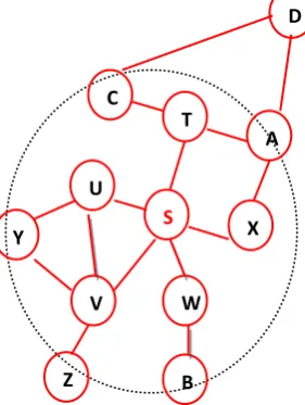
The Zone Routing Protocol (ZRP) [37], [38] is a hybrid routing protocol for mobile ad hoc networks which exploits the good features of both reactive and proactive protocols. The proactive part of the protocol is restricted to a small neighbourhood of a node and the reactive part is used for routing across the network. Each node S in the network has a routing zone and each zone has the size radius corresponding to a value of number of hopes. Fig 3 shows that for the node S, if the radius of the routing zone is n,then nodes T,U,V,W,X,Y,Z,A,B.C are the interior nodes where as node D is the peripheral node .
[image:7.595.359.500.298.485.2]The routing in ZRP based on two procedures: Intra-zone Routing protocol (IARP) and Inter-zone Routing Protocol (IERP). IARP is Proactive approach and it is used inside routing zones and IERP is reactive approach and it is used between routing zones.
Fig 3 All nodes except D are in the routing zone of S with radius =2.
When a node S has packet to send to destination node d. First, the packet is sent in the Intrazone of the source node.If the destination belong to same zone ,then it deliver the packet directly.otherwise source node S sends a “Route Request“ to all peripheral nodes. At reception of the message to the peripheral node ,if it find the node d ,it sends a“Route Reply“ message back to the node s,indicating the path;otherwise peripheral node will repeat the same operation untill node d is located.There can be multiple path that a source node s can choose to reach at destination d.Then,source node can choose the best path based on the criterion like shotest path,least delay path etc.
Advantages and Disadvantages
ZRP reduces the control overhead compared to the Root request flooding mechanism employed in on demand approaches and the periodic flooding of routing information packets in table driven approaches. But in the absence of a query control ZRP tends to produce higher control overhead then the aforementioned schemes. Also the decision on the zone radius has a significant impact on the performance of the protocol.
T
A C
D
S
U
Y
V
Z
W
A
2.3.2 HARP
The Hybrid Ad hoc Routing Protocol (HARP) [39] is a hybrid routing scheme, which exploits a two-level zone based hierarchical network structure. Different routing approaches are utilized in two levels, for intra-zone routing and inter-zone routing, respectively.
The Distributed Dynamic Routing (DDR) algorithm is exploited by HARP to provide underlying supports. In DDR, nodes periodically exchange topology messages with their neighbors. A forest is constructed from the network topology by DDR in a distributed way. Each tree of the forest forms a zone. Therefore, the network is divided into a set of non-overlapping dynamic zones. A mobile node keeps routing information for all other nodes in the same zone. The nodes belonging to different zones but are within the direct transmission range are defined as gateway nodes. Gateway nodes have the responsibility forwarding packets to neighboring zones. In addition to routing information for nodes in the local zone, each node also maintains those of neighboring zones.
As in ZRP, the intra-zone routing of HARP relies on an existing proactive scheme and a reactive scheme is used for inter-zone communication. Depending on whether the forwarding and the destination node are inside the same zone, the respective routing scheme will be applied.
Advantages and Disadvantages
In HARP, the network is divided into non-overlapping zones dynamically by DDR through mapping the network topology to a forest. For each node in HARP, the topology knowledge for neighboring nodes is also needed and the zone level stability is used as a QoS parameter to select more stable route.
2.3.3 ZHLS
The Zone-based Hierarchical Link State routing (ZHLS) [40], is a hybrid routing protocol. In ZHLS, mobile nodes are assumed to know their physical locations with assistance from a locating system like GPS. The network is divided into non-overlapping zones based on geographical information.
ZHLS [41] uses a hierarchical addressing scheme that contains zone ID and node ID. A node determines its zone ID according to its location and the pre-defined zone map is well known to all nodes in the network. It is assumed that a virtual link connects two zones if there exists at least one physical link between the zones. A two-level network topology structure is defined in ZHLS, the node level topology and the zone level topology. Respectively, there are two kinds of link state updates, the node level LSP (Link State Packet) and the zone level LSP. A node level LSP contains the node IDs of its neighbors in the same zone and the zone IDs of all other zones. A node periodically broadcast its node level LSP to all other nodes in the same zone. Therefore, through periodic node level LSP exchanges, all nodes in a zone keep identical node level link state information. In ZHLS, gateway nodes broadcast the zone LSP throughout the network whenever a virtual link is broken or created. Consequently, every node knows the current zone level topology of the network.
Before sending packets, a source firstly checks its intra-zone routing table. If the destination is in the same zone as the source, the routing information is already there. Otherwise,
the source sends a location request to all other zones through gateway nodes. After a gateway node of the zone, in which the destination node resides, receives the location request, it replies with a location response containing the zone ID of the destination. The zone ID and the node ID of the destination node will be specified in the header of the data packets originated from the source. During the packet forwarding procedure, intermediate nodes except nodes in the destination zone will use inter-zone routing table, and when the packet arrives the destination zone, an intra-zone routing table will be used.
Advantages and Disadvantages
The ZHLS [42] reduces the storage requirements and the communication overhead created because of mobility. The zone level topology is robust and resilient to path breaks due to mobility of nodes. The disadvantage of this protocol is the additional overhead incurred in the creation of the zone level topology. Also, the path to the destination is sub-optimal.
2.3.4 CEDAR
The Core-Extraction Distributed Ad Hoc Routing (CEDAR) [43], is a Hybrid routing protocol. In CEDAR, a subset of nodes in the network is identified as the "core". Core is determined according to a distributed algorithm and the number of core nodes is kept to be small. To select core nodes, neighboring nodes periodically exchange link state messages.
Every mobile node in the network must be adjacent to at least one core node and picks this core node as its dominator. The algorithm guarantees that there is a core node at most 3 hops away from another core node. Every core node determines paths to core node nearby using localized broadcasts. The link state information is propagated only among core nodes. The propagation distance of a link state through the network is a function of its stability and bandwidth. Only the state of stable links with high bandwidth is propagated far away and the link state information includes dominators of link endpoints. Hence, in CEDAR [44], a core node not only knows the state of local links but also the state of stable and high bandwidth links far away.
When a source node wants to send packets to its destination, it informs its dominator core node. Then the dominator of the source finds a route in the core network to the dominator of the destination. This is done by means of a DSR-like route discovery process among core nodes. Then, core nodes involved in the previous step build a route from the source to the destination. Locally available link state information is used according to the QoS requirement such as link bandwidth. It is not necessary for the route to include core nodes.
Advantages and Disadvantages
3.
CONCLUSION
Routing is an essential component of communication protocols in mobile ad hoc networks. The design of the protocols are driven by specific goals and requirements based on respective assumptions about the network properties or application area. We have reviewed 19 unicast routing protocols from research papers published between 1998 and 2012. We have also provided a classification of these schemes according the routing strategy i.e., table driven, on-demand and hybrid, highlighting their features and characteristics. A lot of research papers have also compared the performance of routing protocols. The tradeoff between proactive and reactive routing strategies is quite complex. Which approach is better for unicaste routing protocols depends upon the Network structure parameters( network size, mobility, link capacity, connectivity and data traffic) and performance metrics( throughput, control overhead, hop count, end to end delay etc.) of routing protocols[30]. In order to choose routing strategy, first the network structure parameters have to be understood. Then, optimal routing protocol will be decided based on the performance metrics. Based on the review, proactive protocols yield better throughput, minimized end to end delay than the reactive protocols. Whereas in terms of routing load and hop count, reactive protocols perform better than the proactive protocols.
It has been observed that any particular algorithm or class of algorithm is not best for all scenarios. Each protocol has definite advantages and disadvantages and has certain situations for which it is well suited.There are many issues which have not been considered in this paper e.g. related to quality of service or recent work on position-based and geographical routing. This will be subject of further investigations.
4.
REFERENCES
[1] Elizabeth M. Royer,Santa Barbara Chai-Keong Toh, “A Review of current Routing protocols for Adhoc Mobile wireless Networks”, IEEE Personal communication April 1999, 46-55.
[2] IETF Manet charter,
http://www.ietf.org/html.charters/manet-charter.html
[3] Farhat Anwar, Md. Saiful Azad, Md. Arafatur Rahman, Mohammad Moshee Uddin, “Performance Analysis of Ad hoc Routing Protocols in Mobile WiMAX Environment”, IAENG International Journal of Computer Science 2008, Vol. 35, Issue. 3. [3]
[4] X. Hong, K. Xu and M. Gerla, 2002. Scalable Routing Protocols for Mobile Ad Hoc Networks. IEEE Network Magazine.
[5] Du, X. 2005. Designing efficient routing protocol heterogeneous sensor network. In proceeding of the 24th IEEE international Conference on Performance Computing and Communication.
[6] Mamoun Hussein Mamoun 2011.” A New Proactive Routing Protocol for MANET”. IEEE Advances on Information Sciences and Service Sciences 2011,vol3,No.2,pp-132-140.
[7] L. M. Feeney 1999, A Taxonomy for Routing Protocols in Mobile Ad Hoc Networks. Swedish Institute of Computer Science.
[8] Corson, S. & Macker ,J. 1999.Mobile Ad Hoc Networking (MANET): Routing Protocol Performance Issues and Evaluation considerations. Internet Engineering Task Force (IETF), Network Working Group (RFC 2501).
[9] M.Sreerama Murty and M.Venkat Das, “Performance Evaluation of MANET Routing Protocols using Reference Point Group Mobility and Random Waypoint Models”, International Journal of Ad hoc, Sensor & Ubiquitous Computing (IJASUC) March 2011,Vol.2, No.1, 33-42.
[10]Mohamed Adnene Zayene, Nabil Tabbane, Refaat Elidoudi 2009. Performance Evaluation of Greedy Perimeter Stateless Routing Protocol in Ad Hoc Networks. In proceeding of the Fourth International Conference on Computer Sciences and Convergence Information Technology.
[11]S. Gupte and M. Singhal, “Secure Routing in Mobile Wireless Ad Hoc Networks,” Ad Hoc Networks 2003, No 1, 151-174.
[12]C. S. R. Murthy, B. S. Manoj 2004, Ad Hoc Wireless Networks: Architecture and Protocols. Pearson Ltd.
[13]Changling Liu, Jörg K. 2005 A Survey of Mobile Ad Hoc network Routing Protocols. Technical Report Series University of Ulm, Nr. 2003-08.
[14]Alexander Klein 2008. Performance Comparison and Evaluation of AODV, OLSR and SBR in Mobile Ad-Hoc Networks. Innovation Works, IEEE 3rd International Symposium on Wireless Pervasive Computing.
[15]S. Gowrishankar, T.G. Basavaraju, Subir Kumar Sarkar 2010.Simulation Based Overhead Analysis of AOMDV, TORA and OLSR in MANET Using Various Energy Models. In proceedings of the World Congress on Engineering and Computer Science.
[16]Zhi Ren and Yi Zhou Wei Guo 2005. An Adaptive Multi- Channel OLSR Routing Protocol Based on Topology Maintenance. In proceeding of the IEEE International Conference on Mechatronics & Automation.
[17]Ulrich Herberg, Thomas Clausen, Robert Cole 2010. MANET Network Management and Performance Monitoring for NHDP and OLSRv2. In proceeding of the International Conference on Network and Service Management – CNSM 2010.
[18]Yasunori Owada, Kenta Tsuchida, Taka Maeno, Hiroei Imaix and Kenichi Mase 2006. OLSRv2 Implementation and Performnce Evaluation. 3rd OLSR Workshop.
[19]G. Pei, M. Gerla, and T.-W. Chen 2000.Fisheye state routing: A routing scheme for ad hoc wireless networks. In the proceeding of IEEE ICC.
[20]Ding junxia 2010. Simulation and Evaluation of the Performance of FSR Routing Protocols Based on Group Mobility Model in Mobile Ad Hoc. In the proceeding International Conference on Computational Intelligence and Software Engineering.
IEEE International Symposium on Parallel and Distributed Processing with Applications.
[22]Pei G, Gerla M, Hong X 2000. LANMAR: Landmark Routing for Large Scale Wireless Ad Hoc Network with Group Mobility. First Annual Workshop on Mobile and Ad Hoc Networking and Computing (MobiHoc 2000).
[23]Tsuchiya PF 1988. The Landmark Hierarchy: A New Hierarchy for Routing in Very Large Networks. Computer Communication Review, Issue 4.
[24]Jun-Hu Zhang, Hui Peng, Feng-Jing Shao 2011. Energy Consumption Analysis of MANET Routing Protocols based on Mobility Models.In proceeding of the Eighth International Conference on Fuzzy Systems and Knowledge Discovery (FSKD).
[25]Jiang M., Li J., and Tay Y. C. 1999. Cluster Based Routing Protocol. IETF MANET Working Group, Internet-Draft.
[26]Dr. Mamoun Hussein Mamoun ,”A Proposed Hybrid Routing Protocol for MANET”,Journal of Mathematics and Technology 2010, vol. 1,no.1, 126-130.
[27]Rendong Bai and M. Singhal 2006. DOA: DSR over AODV routing for Mobile Ad-Hoc Networks. IEEE Transactions on Mobile Computing.
[28]Misra ,R.; Manda,C.R.; “ Performance Comparison of AODV/DSR On-Demand Routing Protocols for Ad Hoc Networks in Constrained Situation”, IEEE ICPWC 2005.
[29]Beaubrun, Badji Molo “Using DSR for Routing Multimedia Traffic in MANETs”, International Journal of Computer Networks Communications (IJCNC) 2010, Vol.2, No.1.
[30]Zhijiang Chang, Georgi Gaydadjiev, Stamatis Vassiliadis,“Routing Protocols for Mobile Ad-hoc Networks: Current Development and Evaluation”, Computer Engineering Laboratory, EEMCS Delft university of technology Mekelweg.
[31]Mohamad Nazim Jambli, Kartinah Zen, Halikul Lenando Alan Tully 2011.Performance Evaluation of AODV Routing Protocolfor Mobile Wireless Sensor Network In Proceedings of the IEEE 7th International Conference on IT in Asia(CITA 11) .
[32] Zahian Ismail, Rosilah Hassan 2011. Effects of Packet Size on AODV Routing Protocol Implementation in Homogeneous and Heterogeneous MANET. In Proceedings of the IEEE Third International Conference on Computational Intelligence, Modelling & Simulation.
[33] Tamilarasan-Santhamurthy,” A Quantitative Study and Comparison of AODV, OLSR and TORA in Routing
Protocols MANET”, International Journal of Computer Science Issues 2012, Vol. 9, Issue 1, No 1, 364-369.
[34]De Rango, f. 2010.A modified location-aided routing protocol for the reduction of control overhead in ad hoc wireless networks. In proceeding of the 10th International conference on Telecommunication.
[35]y.ko and N H vaidya 1998. Location Aided Routing(LAR) in mobile adhoc networks. In proceeding of the fourth Annual ACM/IEEE international Conference on Mobile Computing and Networking (MOBICOM 1998).
[36]Christoph Sommer and Falko Dressler 2007. The DYMO Routing Protocol in VANET Scenarios. In proceeding of the 66th IEEE Conference on Vehicular Technology. [37]Z. J. Haas, M. R. Pearlman and P. Samar 2002.The Zone
Routing Protocol (ZRP) for Ad Hoc Networks. IETF Internet Draft.
[38]T. Lin, S. Midkiff, and J. Park, “A framework for ad hoc routing protocols,” In WCNC: Wireless Communications and Networking. IEEE wireless Computer Society, 2003, 1162–1167.
[39]Navid Nikaein, Christian Bonnet and Neda Nikaei 2001. HARP - Hybrid Ad Hoc Routing Protocol, in proceeding of IST 2001: International Symposium on Telecommunications, Iran/Tehran 2001.
[40]Hamma T. 2006. An Efficient ZHLS Routing Protocol for Mobile Ad Hoc Networks. In Proceedings of the 17th International Conference on Database and Expert Systems Applications (DEXA'06).
[41]NetworksSanaz AsadiniaMarjan Kuchaki Rafsanjani ,”Improvement of ZHLS Routing Protocol Based on Principles of Swarm Intelligence in Mobile Ad hoc”, American Journal of Scientific Research 2012, 51-64.
[42]Satoshi Kamidate, Takashi Katoh, Bhed Bahadur Bista and Toyoo Takata 2007.Fault-tolerant ZHLS Routing Protocol for Wireless Mobile Ad Hoc Network. In Proceedings of the 7th WSEAS International Conference on Multimedia, Internet & Video Technologies.
[43]P. Sinha,R Sivakumar and V Bharghawan 1999,CEDAR: A Core extraction Distributed Adhoc Routing Algorithm, ÏEEE journal on selected areas In communications .vol17,no.8,1454-1466.
[44]P. Sinha, R. Sivakumar and V. Bharghaven 1999, CEDAR: a Core-Extraction Distributed Ad hoc Routing algorithm. IEEE INFOCOM, March .
![Fig 2: CGSR Packet Routing [4]](https://thumb-us.123doks.com/thumbv2/123dok_us/8106517.789619/4.595.54.266.695.753/fig-cgsr-packet-routing.webp)