Reducing Computation Complexity in Interference-aware
Energy-efficient Geographical Routing for Low Rate
Wireless Personal Area Networks
Yuan Hu
Department of Electronic, Information and Communication Engineering,
Konkuk University
Younggoo Kwon
Department of Electronic, Information and Communication Engineering,
Konkuk University
ABSTRACT
The geographical routing for IEEE 802.15.4a standard is targeted towards providing an infrastructure for ultra-low complexity, ultra-low cost, ultra-low power consumption, and low data rate wireless connectivity among inexpensive devices. Existing interference aware graphical routing methods have shown to reduce energy consumption with increase in data delivery ratio. This paper presents a modification in interference aware energy efficient graphical routing for IEEE 802.15.4a networks. Using localized update policy, the number of computations required is reduced for finding the optimal energy efficient route to destination. Simulation results show that the proposed scheme can achieve same performance as the existing topology in terms of route length and delivery ratio. Due to reduction in number of computations the overall energy consumption of the network is reduced. Reduction in complexity, computations and energy consumption make the proposed scheme useful for achieving low-power consumption, low cost solutions for IEEE 802.15.4a networks.
General Terms
Energy, cost, computations, packet, algorithm.
Keywords
Energy efficient topology, Geographical routing, Interference, IEEE 802.15.4a.
1.
INTRODUCTION
IEEE 802.15.14a/ZigBee standard provides the definition of topology and framework for simplistic, low cost, low speed ubiquitous communication between devices in wireless private networks [1]. Inherently, two routing methods have been proposed in ZigBee standard: the ad-hoc on demand distance vector routing protocol (AODV) and the hierarchical routing protocol (HRP) [1]. Geographical routing methodologies have been proposed in various research works to outperform AODV or HRP in presence of location information [2][3][4]. The greedy algorithm is often used in geographical routing topology. However, the performance of greedy algorithm is severely degraded by the presence of interference caused by obstacles. Many algorithms have been proposed to improve the greedy forwarding [5] [6] [7]. In [4] log-distance path loss model is used to estimate the lowest energy/distance value for choosing the next hop neighbor. The delivery ration in this scheme is significantly dependent on the near-by obstacles. In [6] and [7] the rate of packets reception is continuously monitored to decide the next hop neighbor. Sudden change in environment is reflected poorly in
the rate of reception and hence, these algorithms fail to adapt to environmental changes.
In [8] and [9], an interference aware energy efficient geographical routing algorithm (IEG) for IEEE 802.15.4a networks is presented. Using beacon packets the energy cost for routing between various nodes was computed. The routing was by choosing a path that consumes least amount of energy. The energy cost estimation involved the interference computation and hence, IEG routes the packets around the interference region. The energy cost computation and routing table construction in IEG is based on the transmission of beacon from all the nodes in the network. With change in interference, the routing tables of all the nodes must be updated. This in turn requires beacon packet transmission by all the nodes. As the number of nodes increase the number of beacon signal transmitted increases significantly. Therefore, the network is increasingly busy with transmission of beacon signals rather than the actual data. On the other hand, as the number of nodes increases, the number of computations done in a node for energy cost estimation also increases significantly.
In this paper, the modifications in IEG routing are presented to reduce the number of overall computations. It is shown that after initialization the nodes pass on the information of power requirement through beacon signals. A mechanism of information sharing using beacon signal is presented. In a best case situation, it can be shown that the energy consumption computation can be avoided in approximately 50% of nodes. In section II IEG routing is briefly discussed. In section III, the proposed modifications are presented. In section V, the simulation environment and results are presented, followed by conclusion.
2.
ENERGY-EFFICIENT
INTERFERENCE-AWARE
GEOGRAPHICAL ROUTING
2.1
Interference-Aware Minimum Energy
Consumption Estimation
/10 /10 /10
10log(10
PN10
PI10
TH)
TH RX
P
(1) where, PN and PI denotes the noise power and the interference power in dBm; ζTHis the SINR threshold for a successful reception in dB. The noise power depends on hardware used. The minimum power required for successful transmission,
min
TX
P
, is given as min(
)
(
)
TH(
)
TX RX
P
dBm
PL dB
P
dBm
(2) where PL is the path loss between the sender and the receiver due to the distance and the obstacles; σ is the deviation of the path loss in a fading channel.The total energy, E, required for successfully transmitting a data packet is given by
(
)
TX DATA RX LIFS BO ACK SIFS
E
E
T
E
T
T
T
T
(3) where, ETX and ERX denote the power consumption in mW in the transmit mode and the receive mode respectively. TDATA, TACK, TLIFS, TSIFS, and TBO denote the durations of the data packet, the acknowledge packet, the long inter-frame space, the short inter-frame space, and the back-off respectively [9]. For a given hardware proportionality factor of c, the power consumption in the transmit mode is proportional to the minimum transmit power (ETX ∝ c ·min
TX
P
). Hence, it is evident from (3) that since, most of the entities are constant; the energy consumption value is mostly affected by the interference effects when a node transmits a packet.2.2
Energy-efficient Geographical Routing
Scheme
In [8], energy efficient version of interference aware routing is presented. The nodes measure the receiver power threshold,
TH RX
P , periodically. The change in interference near a node is conveyed to other nodes by broadcast mechanism at maximum transmission power,
P
TXmax. The receiver measures the receive power,P
RX, and determines the path loss asmax
( ) TX ( ) RX( )
PL dB P dBm P dBm (4)
Using (2) the minimum power for transmission is calculated. For each neighbor, the transmitter computes the total energy, E, to transmit the packet from node a to node b using (3). Advance to destination distance, ADV, is calculated as
( , )
( , )
ADV
d a b
d c b
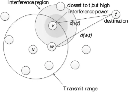
(5)where, d(a, b) denotes the distance between the node a and the destination b. The source node a then transmits the packet to node c with the lowest E/ADV. The power and energy requirement increases with interference. Hence, routing with minimum E/ADV minimizes the total energy consumption along the routing path. Fig. 1 shows the basic principle involved in IEG.
2.3
Computation complexity
In IEG, the computations are done for establishing and updating the energy consumption in the local routing table. The energy values are calculated from power requirement values. From the previous discussion it can be noted that for establishing and updating the routing table with energy values (1), (2), (3) and (4) must be computed. If each arithmetic operation and memory fetch is considered as one operation (1)
requires three divisions, four memory fetch from look-up
table to compute logarithmic values and three additions. Hence, 10 operations are required in (1). Similarly, (2) requires three operations. In (3) the values of TDATA, TACK, TLIFS, TSIFS, and TBO are fixed while ETX is variable entities. Hence, only two multiplications and one addition is sufficient to calculate (3). Finally, (4) requires 1 subtraction operation. Calculation of ETX (∝ c ·
min
TX
P
) requires one operation. Hence, in each node 14 computations are made for computation of energy for each neighboring node.For computation of energy values and constructing routing table, beacon packets are transmitted amongst all the nodes. Hence, for N number of nodes each node broadcasts beacon. All N-1 nodes perform 16 computations to compute the energy for routing table. In the worst case, the procedure is repeated for N nodes. In other words, for n nodes, 16 computations are done in N-1 nodes for n number of beacons. Hence, the total number of computations in IEG, OIEG, is
given as
1
16 IEGO N N (6)
In a generalized case, if CE number of computations are required for computation of energy values, the total number of computations in IEG, OIEG, is given as
1
IEG E
O N N C (7)
3.
PROPOSED MODIFICATION
3.1
Computations through local update
Consider two nodes p and q. In IEG routing [8], p transmits a beacon containing PRXTH value at maximum transmission power. The node q receives the beacon and computes the path loss value, PL, using (4), minimum transmission power,P
TXmin , from (2) and energy requires from transmission from q to p using (3). Thereby, q computes or updates its routing table. Node q then transmits a beacon packet, containingP
RXTHvalue, at maximum transmission power, so that p can compute path loss value, PL, using (4), minimum transmission power,P
TXmin , from (2) and energy requires from transmission from p to q using (3). In other words, identical computations are done at both the ends. In a stable environment, the path loss from node p to q is same as path loss from q to p. If the interference value is same at both the nodes and same hardware settings are used, the value of receiver threshold, PRXTH , minimumFig. 1. Interference aware energy efficient geographical routing algorithm (IEG) basic principle.
u w
v
t
destination Interference region
d(w,t) d(v,t)
Transmit range closest to t,but high
[image:2.595.323.546.76.234.2]transmission power,
P
TXmin , and energy requires from transmission from one node to another will also be same. In other words, for same interference condition at node p and q, the minimum power required for transmission at q is given asmin min
, ,
TX q TX p
P P (8)
Once the minimum transmission power,
P
TXmin, is calculated at one node, it can be transmitted along with PRXTH in beaconpacket. The receiving node can then copy the
P
TXminvalue from beacon thereby avoiding the computations.In a practical case, the interference at different nodes can be different. Let the value of receiver threshold and minimum transmission power for Nth node be given by PRX NTH, andPTX Nmin, ,
respectively.
As discussed earlier, path loss value and deviation of the path loss in a fading channel will be same for both the nodes. Therefore, from (2) the minimum transmission power at node p, is given as
min
, ( ) ( ) , ( )
TH
TX p RX p
P dBm PL dB P dBm
(9)Similarly, the minimum transmission power at node q, is given as
min
, ( ) ( ) , ( )
TH
TX q RX q
P dBm PL dB P dBm
(10)The receiver power threshold of node q can be expressed in terms of receiver power threshold of node p as
min
, ,
, ,
(
)
(
)
(
)
(
)
TH
TX q RX p
TH TH
RX q RX p
P
dBm
P
dBm
P
dBm
P
dBm
(11)Combining (10) and (11)
min
, ,
, ,
(
)
(
)
(
)
(
)
(
)
TH
TX q RX p
TH TH
RX q RX p
P
dBm
PL dB
P
dBm
P
dBm
P
dBm
(12)From (9) and (12)
min min
, ,
, ,
(
)
(
)
(
)
(
)
TX q TX p
TH TH
RX q RX p
P
dBm
P
dBm
P
dBm
P
dBm
(13)In (13), the value of PTX pmin, and PRX pTH, is received in beacon
packet. Hence, at the receiving node the minimum transmission power is computed from the values received from the beacon.
It can be seen that (13) represents a generalized equation for computing minimum required transmission power. If the interference at both the nodes is same, the minimum receiver power threshold TH, ( )
RX q
P dBm and TH, ( )
RX p
P dBm will be same
and cancel out in (13). This condition is represented in (8). Hence, the relation between (8) and (13) validates the proposed hypothesis that, in the receiving node, the minimum transmission power is computed from the values received from the beacon.
In certain conditions the interference changes rapidly. However, the total deviation is not significant. Hence, additional constraints must be added in (11) to make provision for selective update. Let the time based minimum transmission power be given as
min min
, ,
( )
,( )
,( )
TH TH
q
t
P
TX qP
TX pt
P
RX qt
P
RX pt
(14)where all the power values are in dBm.
Similarly, for different time instances t1 and t2, (t1 > t2), the
difference in receiver power threshold can be given as
2 , ( )2 , ( )1TH TH
q t PRX q t PRX q t
(15)Using (12) and (13) the expression for minimum transmission power given by (11) is modified as
2 2
min , 2
1
( ) 2
( )
( )
q q
TX q
q
t for t
P t
t else
(16)
3.2
Reducing computations throughout
network
[image:3.595.51.282.319.525.2]Consider the network of N nodes. In existing IEG routing the routing table configuration starts with broadcast of beacon packet from first node to other nodes. The neighboring nodes receive the packet and calculate power and energy values for their respective routing table. Thereafter, next node starts broadcasting the beacon packet. The process continues till all the nodes have transmitted their corresponding beacon packets. This situation is shown in Fig. 2
Fig. 2. Beacon packet transfer amongst nodes in IEG routing.
As discussed earlier, in this configuration the each node performs the computations and the total number of computations across the network is given by (7).
In previous section it was shown that in the proposed modified IEG scheme the computations in some of the nodes can be avoided. Let the first node initiate the broadcast of beacon packet. Fig. 3 shows the beacon packet transmitted by node 1.
Fig. 3. Data segment of Beacon packet broadcast from node 1.
The neighboring nodes will calculate the power and energy values. After computations, second node broadcast beacon packet containing its minimum receiver power value along with the minimum required transmission power value from node one to node two. Fig. 4 and Fig. 5 shows the beacon packet transmitted by node 2 and 3 respectively.
Fig. 4. Data segment of Beacon packet broadcast from node 2.
1
2
3
N
...
XXX
,1(
)
TH RX
P
dBm
,2
(
)
THRX
P
dBm
min,1 2 TX
[image:3.595.379.478.333.427.2]Fig. 5. Data segment of Beacon packet broadcast from node 3.
The first node receives the beacon with the power values and uses (16) to either copy or compute the power and energy values. Other neighboring nodes copy the power and energy values of packet transmission from node one to node two. Therefore, node one does not perform computations if the interference condition between node one and node two are identical.
After computations third node broadcast beacon packet containing its minimum receiver power value along with the minimum required transmission power value from node one to node three and node two to node three.
Hence, for N nodes, N-1 nodes perform power and energy computations when the first node broadcast the beacon packet. When second node broadcast the beacon packet, node one performs data copy while N-2 nodes perform power and energy computations. Considering this geometric progression when the rth node broadcast the beacon packet, r-1 nodes will copy the data from the received beacon while N-r nodes will calculate the power and energy values. Finally, when the Nth node broadcast the beacon all the remaining nodes will copy the data from beacon without computations. As discussed earlier let CE be the number of computations required for computation of energy values. Hence, the total number of computations in proposed scheme across the network, Op, is given as
1
( 2)
3
... 1p E
O N N N C (17)
1
1
1
2 N
p E E
i
N N
O i C C
(18)The value obtained for total number of computations obtained in (18) validates our hypothesis that under identical noise condition 50% of nodes will not require power and energy computations.
4.
MODIFIED ENERGY-EFFICIENT
INTERFERENCE-AWARE
GEOGRAPHICAL ROUTING SCHEME
Based on the previous discussion the proposed modified Energy-efficient Interference-Aware Geographical Routing Scheme can be summarized as1. All the nodes compute interference and receiver power threshold value periodically.
2. The routing table is established using energy values and hence, the nodes start broadcasting the beacon packets in a pre-established order.
3. Every node x, transmits the beacon packet containing the location information, receiver power threshold value and the minimum required transmission power for all the nodes from 1 to x-1.
4. Neighboring nodes y, compute the minimum required transmission power from node x to y, using the beacon packet data and locally obtained receiver power threshold value.
5. Once all the nodes have finished broadcast of their
beacon packets, the routing tables in each nodes are finalized using the energy values calculated after reception of each beacon packet.
6. For data transmission from node a to b, the packet size and estimates the energy consumption, E, for each neighbor by using (3). The node a then forwards the packet to the node c with the lowest E/ADV value [8].
7. Packets are forwarded to the neighbor with the positive E/ADV value to prevent the routing loop.
8. When no nodes exists for positive E/ADV value the packet can be transferred to nearest node.
9. The procedure is repeated if the interference condition at some node changes and the routing tables of various nodes are to be updated.
5.
IMPLEMENTATION AND RESULTS
The performance of the proposed modified IEG (mIEG) routing algorithm was compared with existing IEG algorithm, greedy algorithm [5]-[7], and the PRR × distance algorithm in large scale network by using the ns-2 simulator. The log distance path loss model was used for simulation. The path loss at a distance d is defined as
0 10 log 0PL d PL
d d X (19)where PL0 is the path loss at the close-in reference distance d0,
η is the path loss exponent, and Xσ is a zero mean Gaussian distributed random variable with standard deviation σ. The hardware dependent values were calculated using the nanoLOC kit which consists of CSS-based NA5TR1 transceiver [10]. Table 1 shows different parameter values used in simulations. The power consumption and duration values are drawn from the data sheet of the NA5TR1. Hundred 802.15.4a nodes were placed randomly in 300×300m plane and two 802.11g nodes were placed at (150, 150). Two farthest nodes were selected and 100-byte packets were sent from one to another at the rate of 1 packet per 1.5 seconds. On the other hand, MPEG-4 video file with 800-byte packet size and bit rate of 56kbps, was transferred between the 802.11g nodes using the Poisson traffic model [11].
Table 1. PARAMETERS USED IN SIMULATION
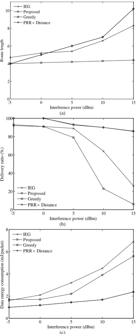
Fig. 6 shows (a) the route length, (b) the delivery ratio, and (c) the energy consumption of the algorithms as a function of the interference power.
,3
(
)
THRX
P
dBm
P
TXmin,1 3P
TXmin,2 3Parameter Value Parameter Value
d0 1m TLIFS 24us
PL0 40dB TSIFS 8us
η 2.7 TACK 36us
σ 2dB ETX 75mW
M 3dB ERX 82.5mW
Data rate 250kbps PN 95dBm
max TX
(a)
(b)
(c)
Fig. 6. (a) The route length, (b) the delivery ratio, and (c) the energy consumption of various routing algorithms as a
function of the interference power
As discussed in [8], that although, the greedy algorithm has the shortest route length, the delivery ratio reduces significantly with increase in interference. Similarly, the PRR × distance algorithm shows better performance than the greedy algorithm by using the links with over 80% PRR. However, the PRR × distance algorithm requires the multiple
data exchanges for estimation of the PRR and the routes are modified after considerable amount of packet loss. The proposed algorithm requires the longest route but it achieves the highest delivery ratio and the lowest energy consumption. The proposed scheme introduces the changes in the method of computation of power and energy values. However, the criterion for next hop node selection is same as IEG [8]. Hence, similar to IEG [8], the proposed algorithm routes packets around the interference region when the interferences are detected.
Fig. 7 shows the comparison of number of computations performed across the network in proposed modified and original IEG routing method. By comparing (7) and (16) it can be seen that the number of computations are reduced by 50% for all the interference values.
Fig. 7. Comparison of number of computations in proposed modified IEG and original IEG algorithm.
Fig. 8 shows the energy consumption in bacon packet broadcast and computations across the network.
Fig. 8. Total energy consumption in modified IEG and original IEG routing algorithm.
It can be seen that due to reduction in computations, the energy consumption in routing table construction is reduced in proposed scheme. By comparing the results obtained in Fig. 6 and Fig. 8, it can be concluded that the proposed routing scheme achieves the same performance as the original IEG with reduced computation complexity and reduced over-all power consumption.
-5 0 5 10 15
0 2 4 6 8 10
Interference power (dBm)
R
o
u
te
l
e
n
g
th
IEG Proposed Greedy PRR Distance
-5 0 5 10 15
0 20 40 60 80 100
Interference power (dBm)
D
el
iv
er
y
r
at
io
(
%
)
IEG Proposed Greedy PRR Distance
-5 0 5 10 15
0 2 4 6 8
Interference power (dBm)
D
at
a
en
er
g
y
c
o
n
su
m
p
ti
o
n
(
m
J/
p
ac
k
et
)
IEG Proposed Greedy PRR Distance
0 20 40 60 80 100
0 2 4 6 8 10
Number of nodes, N
T
o
ta
l
n
u
m
b
er
o
f
co
m
p
u
ta
ti
o
n
(
1
0
3 )
IEG Proposed
-5 0 5 10 15
0 0.2 0.4 0.6 0.8 1
Interference power (dBm)
T
o
ta
l
en
er
g
y
(
J)
[image:5.595.57.296.69.655.2] [image:5.595.318.550.239.412.2] [image:5.595.318.550.480.659.2]6.
CONCLUSION
In this paper, modifications in energy-efficient interference-aware geographical routing (IEG) are presented. It is shown that few nodes compute the power and energy values and broadcast them using beacon packets. The receiving nodes compute the local power and energy values based onreceived data in beacon packet. It is shown that due to value passing in proposed scheme, the computations are either completely avoided or require fewer operations as compared to original IEG algorithm. Simulation results show that the proposed modified IEG routing algorithm (mIEG) can achieve same performance as the existing IEG routing method with reduced computation complexity and reduced over-all energy consumption. Reduced computation complexity, power and energy consumption increases the battery life and hence, provides an efficient alternative to the existing geographical routing methodologies.
7.
REFERENCES
[1] ZigBee Alliance, "ZigBee Specification", online at http://www.zigbee.org, Dec. 2006.
[2] IEEE computer society, "Part 15.4: wireless medium access control (MAC) and physical layer (PHY) specifications for low-rate wireless personal area networks (WPANS) amendment 1: add alternate PHYs", online at http://standards.ieee.org, Aug. 2007.
[3] B. Karp and H. Kung, "Gpsr: greedy perimeter stateless Routing for Wireless Networks", Proc. MOBICOM, Boston, MA, USA, pp.243-254, Aug. 2000.
[4] R. Flury, S. Pemmaraju, and R. Wattenhofer, "Greedy Routing with Bounded Stretch", Proc. INFOCOM, Rio de Janeiro, Brazil, Apr. 2009
[5] R. Veronesi, M. D. Pozzo, V. Tralli, and A. Giovanardi "Energy efficient forwarding strategies for wireless sensor networks in presence of fading and power control", Proc. PIMRC, Berlin, Germany, pp.1383-1388, Sep. 2005.
[6] K. Seada and M. Zuniga and A. Helmy and B. Krishnamacharim "Energy-efficient forwarding strategies for geographic routing in lossy wireless sensor networks", Proc. SENSYS, Baltimore, MD, USA, pp.108-121, Nov. 2004.
[7] S. Lee and B. Bhattacharjee and S. Banerjeem "Efficient geographic routing in multihop wireless networks", Proc. MOBIHOC, Urbana-Champaign, IL, USA, pp.230-241, May 2005.
[8] Junseok Kim and Younggoo Kwon, "Interference-aware Energy-efficient Geographical Routing for IEEE 802.15.4a Networks", IEICE Transaction on Communications, vol.E93-B,no.04, pp.1024-1028, Apr. 2010.
[9] J. Kim and Y. Kwon, "Interference-aware topology control for low-rate wireless personal area networks", IEEE Trans. Consumer Electron., vol.55, no.1, pp.97-104, Feb., 2009.
[10]STMicroelectronics, "High performance CSS transceiver enabling location awareness", online at http://www.st.com, Sep. 2008.