Image Compression via Modified TiBS Algorithm to
Achieve High Compression Rate
Pravin B. Pokle
#Narendra.G. Bawane
*, Ph.D
#Ph.D. Scholar, Deptt. of Electronics Engg, *Principal, S.B.Jain Institute of Engg., B.D.College of Engg, Wardha,India Management and Research, Nagpur, India
ABSTRACT
In recent times the integration of video, audio and data in telecommunication devices has revolutionized communication world. It has proven to be useful to almost every industry: the corporate world, entertainment industry, multimedia, education and even at home. The major problems associated with these applications are the high data rates, high bandwidth and large memory required for storage and computing resources. Even with faster internet speed, throughput rates and advanced network infrastructure, there are major bottlenecks to transfer such high volume data through the network due to bandwidth limitations. There is a need to develop compression techniques in order to make the best use of available bandwidth. Thus storage and compression of these high resolution images plays a vital role in such applications to conserve the energy and processor’s computational resources. This paper presents a lightweight modified TiBS algorithm for image compression and storage. The proposed modified compression method operates on a 3x3 block and is based on pixel removal technique. The results shows that proposed method provides a maximum compression of 33% which is more than that achievable by standard TiBS algorithm.
Keywords
Image compression, DWT, DCT, TiBS (tiny block-size encoding), Huffman, RLE.
1.
INTRODUCTION
The increase in the digital imaging techniques in the last few decades has made it possible to capture high resolution images using hand held devices such as digital cameras, mobile phones, ipads etc. Further with the available wireless technologies it is often required to transfer these images wirelessly from a remote location to a destination location as in case of a wireless sensor network. As these digital images are usually represented by a very large number of bits, communication of a single image from source to sink node involves the transmission of several data packets. This results in large energy consumption at the source node than nodes collecting and forwarding scalar data. As the radio transceivers are one of the most power consuming components on sensor nodes, it is obvious that compression of image data would definitely lead to significant energy savings [1]. Image compression, is the science of reducing the amount of data required to represent an image. The use of available compression techniques like JPEG, JPEG 2000, PNG, SPIHT, etc can serve the purpose to compression the image. But more an image is compressed; more is the need for an ARQ (Automatic Repeat-reQuest) or FEC (Forward Error Correction) based protocol to maintain a certain level of image quality. This error control
algorithm. In [2, 6] comparison of energy consumption of JPEG, JPEG2000 and SPIHT is carried out. These algorithms lead to greater energy consumption than the transmission of the uncompressed image. Transform-based image coding algorithms have been the object of intense research during the last twenty years. Eventually they have been selected as the main mechanism of data compression in the definition of digital image and video coding standards. For example JPEG, MPEG-1, MPEG-2, H.261 and H.263 all rely on an algorithm based on the Discrete Cosine Transform (DCT).
Image compression schemes come under two categories: lossless and lossy compression. Lossless compression uses coding techniques to compress the data while retaining all information content. However, the compression achieved using this method for file size reduction is not sufficient for many applications [3, 9]. On the other hand lossy image compression, as its name implies, results after compression contains the loss of some information content while the file size reduction can be much more significant than obtained with lossless compression. Run-length encoding (RLE) and JPEG compression algorithms are examples of lossless compression. The Lempel–Ziv (LZ) compression methods are among the most popular algorithms for lossless storage. Wavelet and higher-level JPEG are the examples of lossy compression techniques. JPEG 2000 is a progressive lossless-to-lossy compression algorithm. JPEG handles only still images; also another standard called MPEG is used for motion pictures [8, 10].
JPEG is one of the most used image compression that has revolutionized lossy data compression by providing a method to decrease the size of natural images with minimal loss of perceivable data. The codec uses a combination of DCT, quantization matrices, and entropy encoding and Huffman encoding to discard less relevant data and compress the image. However, the JPEG standard causes harsh blocking artifacts, due to the uniform discretization of the image into 8x8 blocks, when images are compressed to low bit rates [4, 11].
The newer standard, JPEG2000 [12], significantly reduces the distortion present after compression. Here first a global wavelet transform to the image is applied, and then EBCOT (Embedded Block Coding with Optimal Truncation Points) encoding is performed, followed by further entropy encoding[5]. The use of EBCOT and entropy coding after the wavelet transformation allows a highly compressed version of the image with very little distortion. However, the algorithm does not provide a technique to take advantage of local patterns within the image, such as a low frequency area in the background of an image, due to the initial global wavelet transform, which prevents this approach from having the highest amount of compression possible.
nowadays is focused on lossy compression that minimizes visual distortion and possibly obtains visually lossless results. In general in any compression algorithms, there are three basic steps:
I/P Compressed
Image
Fig 1: Typical image compression system
In this paper a modified lightweight image compression algorithm called TiBs (tiny block-size image compression), that employs a 3x3 block size instead of a 2x2 block is proposed. The proposed modified TiBS algorithm provides a good trade-off between energy consumption and image quality. Finally a comparison is made between DCT, DWT, Huffman, RLE, TiBS (2x2 block size) and proposed modified TiBS (3x3 block size). The paper is organized as follows: Section 2 describes the technical principles of the TiBS algorithm. In Section 3 we present the proposed modified TiBS algorithm. Section 4 gives the results of the proposed algorithm and finally, Section 5 cover conclusions and provides some future directions.
2.
TiBS ALGORITHM
TiBS is a lossy compression algorithm with very low complexity which provides communication of images in an energy-efficient manner, even for high packet loss rates. Since DCT or DWT is computationally intensive and the Encoder in TiBs does not use DCT or DWT, its working is somewhat different than the conventional structure as shown in figure 1. Figure 2 depict block diagram of TiBS algorithm. This algorithm operates on blocks of 2x2 pixels. Each block is encoded independently, based on three stages: uniform scalar quantization, self-adaptive pixel removal, and variable-length coding. The quantization stage is optional; depending on the user requirements. No quantization stage results in better image quality instead of energy savings. The most original part of TiBS is the self-adaptive pixel removal technique.
Original block of Encoded block 2 x 2 pixels (Bi,j) (B^i, j)
Fig 2: TiBS compression scheme.
Consider a digital image with an array of pixels with width C and height R which are the even integers in colour plane then, ... (1) Where the pixel intensities are represented using m bits. Thus the pixel intensities are integers in the range 0 to M, where
... (2) TiBS algorithm divides the color plane into non overlapping 2×2 blocks of pixels. Let Bi,j denote the block at the ith row and jth column (with 0≤i<H/2 and 0≤j<W/2). Before encoding process Bi,j contains four pixel intensities, denoted X0|i,j, X1|i,j, X2|i,j
and X3|i,j as shown in Figure 3. Let
B
i j,
and ~
,
i j
B
denote the encoded and decompressed version of Bi,j respectively.B
0,0B
0,1 x3|i-1, j-1 x2|i-1, j x3|i-1,j
B
1,0x1|i, j-1 x0|i, j x1|i, j
Bi,j
[image:2.595.304.555.77.217.2]x3|i, j-1 x2|i, j x3|i, j
Fig 3: Representation of 2x2 block Bi,j [5].
2.1
Self-Adaptive Pixel Removal
This step where certain number of pixels from the image are removed in such a way that spatial correlation among the unremoved pixels is retained, so as to estimate the missing pixels at the decoder end. In the standard TiBS algorithm 1-pixel is removed out of the four pixel intensities so that the encoded 2×2 block can be represented with 3×m bits. At the decoder end this missing pixel can be estimated from its surrounding pixels based on spatial error concealment method. One drawback of this method is that the quality of the resulting image cannot be controlled as the magnitude of block distortion can vary from block to block significantly. However this drawback can be dealt with to a good extent by a self-adaptive pixel removal (SAPR) method as proposed in [7]. This SAPR method removes that pixel which induces the smallest block distortion. In this method first
0
|
i j,X
and Do|i,j are computed assuming that Xo|i,j is the removed pixel and so on for the remaining three pixels. Then to find the best pixel to be removed by finding out k such that mink (Dk|i,j) which is the block distortionbetween original and decompressed image. Finally this pixel is removed and its place is inserted into the LSBs of the three retained pixels, using the transform τ as given below.
... (3)
where z ={z1, z2, z3}are the LSB’s of three retained pixels from a set of p € (0, 1, 2, 3)
2.2
Uniform Scalar Quantization
In SAPR method, for each block of 2×2 pixels only one pixel out of four pixels is discarded and hence this achieves a compression ratio of 4:3. Higher compression ratios can be obtained when a scalar quantizer is applied to a block first. Quantization here acts as a rounding off of the input values to decrease the number of distinct output values to a smaller set m′ such that m′< m. As in [7], a simple uniform quantizer as given in equation 1 below represents the quantization levels.
...
... (4) Where QΔ is number of quantization levels, 2Δ is the step size and x is the original pixel intensity, this will show increase in the compression ratio substantially. Basic use of this step is to reduce the number of blocks in an image.
Transform Quantizer Encoder
3.
PROPOSED MODIFIED TiBS
ALGORITHM
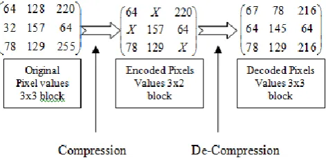
[image:3.595.57.287.210.355.2]In the proposed modified TiBS algorithm, we consider a 3x3 block as shown in figure 4 below. In our proposed modified TiBS method we remove three pixels; the maximum, the minimum and the medium one, out of each 3x3 block. Thus by applying this method each 3x3 block requires 3x2x8 bits as compared to 3x3x8 bits for the uncoded image. By using this method the compression ratio of more than 25% (up to 33%) can be achieved as compared to 25% in case of standard TiBS algorithm discussed above. The encoding and decoding process of proposed method is elaborated with the help of an example below.
Fig 4: Representation of 3x3 block Bi,j.
3.1
Encoding Algorithm
Step1. Partition the given image into 3 x 3 blocks of pixels.
Step2.Reduce the No. of block using uniform scalar Quantization. Consider the following reduce block.
0 1 2
3 4 5
6 7 8
64
128
220
32
157
64
78
129
255
Step3.Search for the min, Max and Medium intensity value Pixels from each block.
Now from the above block the minimum value is 32, the maximum value is 255 and medium value is 128. These pixels are removed so this leaves us the below matrix:
64 220
157 64 78 129
X X
X
The indexes of these removed pixels are 1, 3 and 8 respectively. So this leaves us with the 6 unremoved values as:
The index of the minimum value pixel removed is 3, which give 0011 in binary. This binary is replaced with the binary equivalent of the first value i.e.; 64 of the unremoved pixel as shown below;
(64)10 = (00100000)8
(00100011)
8= (67)
10Similarly the same process is repeated for the maximum and
So we get (216)10 for maximum intensity value and (145)10 for medium value pixel.
Step4. Encode the remaining block with new decimal values as given below.
So this gives the final encoded array of six unremoved pixel which are the transmitted and thus convert our 3x3 block into a 3x2 block of pixels.
3.2
Decoding Algorithm.
Now at the decoder side on receiving the 6 pixel values we reconstruct the 3x3 block as follows with following received pixel values:
Step1. Search for the location for missing pixels in the Received stream.
Step2.Check for the four LSB’s for each of the received decimal value.
Here we getthe position of missing pixel value in the decoded 3x3 block.
Step3. Repeat it for each received numbers.
Step4. Replace the decimal values according to the position obtained as given below which are the missing pixels.
Step5. Now to complete the decoding process the remaining positions are filled out serially from the received pixel values. Note here that the order here is not changed it’s the same as the pixels were originally received. So we get the finally decoded pixel value as:
67
78
216
64 145
64
78 129 216
[image:3.595.307.543.587.703.2]So to sum up we have reconstructed the 3x3 pixel array with transmission of only 3x2 values at the decoder side, this is represented graphically as below.
but the result shows that the loss of image information is not that substantial considering the human vision.
4.
RESULTS OF MODIFIED TiBS
ALGORITHM
[image:4.595.370.475.73.180.2]Figure 6 below shows the input image and figure 7 shows the compressed image using Huffman, DCT and RLE algorithms. Figure 7(a) shows the compressed image using standard TiBS algorithm and figure 7(b) shows the decompressed using our proposed modified TiBS algorithm.
Fig 6: Input image
Figure 7: Compressed Image.
Fig 7(a): Compressed Image using standard TiBS.
Fig 7(b): Compressed Image using proposed modified TiBS.
(a)
(b)
(c)
(d)
Fig 8: Test Images.
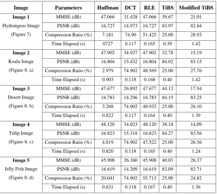
First row of Table I, shows the comparison between Huffman, RLE, DCT, standard TiBS and proposed modified TIBS algorithm based on Minimum mean square error (MMSE), PSNR, compression ratio and time required for the results obtained in figure 6 and 7 above. The rest of the rows directly show the comparison of results among these algorithms with respect four different images.
[image:4.595.56.537.199.544.2]Table I: Comparison of results for different images
Image
Parameters
Huffman
DCT
RLE
TiBS Modified TiBS
Image 1
Hydrangeas Image (Figure 7)
MMSE (dB) 47.066 31.428 47.066 39.67 21.01
PSNR (dB) 16.727 14.973 16.727 83.97 82.84
Compression Ratio (%) 7.181 74.90 51.425 25.00 28.93
Time Elapsed (s) 0727 0.117 0.165 0.39 1.42
Image 2
Koala Image (Figure 8. a)
MMSE (dB) 47.902 34.927 47.902 32.78 15.19
PSNR (dB) 16.804 15.432 16.804 84.02 83.15
Compression Ratio (%) 2.979 74.902 48.569 25.00 27.76
Time Elapsed (s) 0.903 0.118 0.168 0.40 1.42
Image 3
Desert Image (Figure 8. b)
MMSE (dB) 47.677 26.892 47.677 44.12 17.94
PSNR (dB) 16.783 14.296 16.783 84.15 83.25
Compression Ratio (%) 3.268 74.902 48.932 25.00 26.10
Time Elapsed (s) 0.822 0.117 0.164 0.40 1.39
Image 4
Tulip Image (Figure 8. c)
MMSE (dB) 48.120 34.023 48.120 38.18 14.09
PSNR (dB) 16.823 15.318 16.823 84.27 83.56
Compression Ratio (%) 4.819 74.902 47.522 25.00 26.56
Time Elapsed (s) 0.820 0.118 0.165 0.40 1.24
Image 5
Jelly Fish Image (Figure 8. d)
MMSE (dB) 45.908 26.360 45.908 40.03 26.37
PSNR (dB) 16.619 14.209 16.619 83.09 83.71
Compression Ratio (%) 20.041 74.902 55.713 25.00 24.82
Time Elapsed (s) 0.631 0.118 0.167 0.40 1.36
5.
CONCLUSIONS
For compression of digital images there are many algorithms exists and lots of researchers have been proposed various algorithms on image compression. From this literature it is clear that the most of the compression techniques adopted transformation, Quantization and assignment of codeword’s to the pixels in an image. Since transformation step is computationally complex and more intensive and it takes more computation time which will delay the result after compression. Again in conventional methods it is very difficult to recover the missing pixels at the decoder side. In this paper, a modified TiBS algorithm is proposed which uses a 3x3 tiny block size and removes 3 pixels from each of these blocks. The advantage of this method is that since the block size is only of 3 x 3 which is very small, and becomes more robust, computationally easier to encode and becomes less complex as in this method no transformation is required. Also at the decoder side the missing pixels can be easily retained to reconstruct the original image from the block of pixels having small size of 3 x 3 for each block. Since we discard three pixels from each block this method achieves the compression ratio up to 33 % which very much useful for wireless transmission of image data. The results obtained for different images show that the proposed modified TiBS algorithm has better compression ratio and PSNR values as
modifications can be made in the proposed method for further improvement of the PSNR and compression ratio.
6.
REFERENCES
[1] I.F.Akyildiz, W.Su, Y.Sankarasubramaniam and E.Cayirci, "Wireless Sensor Networks: A Survey", Computer Networks 38(4)(2002) 393–422.
[2] Ferrigno L, Marano S, Paciello V, Pietrosanto A. Pietrosanto. Balancing computational and transmission power consumption in wireless image sensor networks. International Conference on Virtual Environments, Human- Computer Interfaces, and Measures Systems. Italy. 2005: 61–66
[3] Shantanu D. Rane and Guillermo Sapiro, Member, IEEE,”Evaluation of JPEG-LS, the New Lossless and Controlled-Lossy Still Image Compression Standard, for Compression of High-Resolution Elevation Data”, IEEE Transactions on Geoscience and Remote sensing, VOL. 39, NO. 10, Oct. 2001
Chen, L. B. Performance Analysis and architecture design for EBCOT encoder in JPEG2000. IEEE Transactions on Circuits and Systems for Video Technology, 17(10), 1336– 1347.-2007.
[5] C. Duran-Faundez, V. Lecuire, "Error resilient image communication with chaotic pixel interleaving for wireless camera sensors", Workshop on Real-World Wireless Sensor Networks (REALWSN 2008), ACM, Glasgow, Scotland (2008), pp. 21–25.
[6] Cristian Duran-Faundez, Vincent Lecuire, Francis Lepage, "Tiny block-size coding for energy-efficient image compression and communication in wireless camera sensor networks", Signal Processing: Image Communication 26 (2011) 466–481. 2011 Elsevier
[7] Z. Wang, A. C. Bovik, H. R. Sheikh and E. P. Simoncelli, “Image quality assessment: From error visibility to
structural similarity,” IEEE Transactions on Image Processing, Vol. 13, no. 4, 2004.
[8] B. Goossens, A. Pizurica, and W. Philips, “Removal of correlated noise by modeling the signal of interest in the wavelet domain,” IEEE Trans.Image Process., vol. 18, no. 6, pp. 1153–1165, Jun. 2009.
[9] R. C. Gonzalez and R. E. Woods, "Digital Image Processing", 2nd Ed., Prentice Hall, 2004.
[10] Wallace, G. K. “The JPEG Still Picture Compression Standard”, Comm. ACM, vol. 34, no. 4, April 1991, pp. 30- 44.
[11] Grzegorz, P. (2005).Ahigh-performance architecture for embeddedblock coding in JPEG 2000. IEEE Transactions on Circuits and Systems for Video Technology, 15(9), 1182– 1191.
![Fig 3: Representation of 2x2 block Bi,j [5].](https://thumb-us.123doks.com/thumbv2/123dok_us/8065694.777785/2.595.304.555.77.217/fig-representation-x-block-bi-j.webp)